Advertisement
Quick Links
Instructions – Parts List
STAINLESS STEEL
Dura–Flo 900t Pumps
With Severe–Duty Rod and Cylinder
U.S. Patent No. 5,456,583
Foreign Patents Pending
Important Safety Instructions
Read all warnings and instructions in this manual.
Save these instructions.
See page 2 for model numbers and maximum
working pressures.
GRACO INC. P.O. BOX 1441 MINNEAPOLIS, MN 55440–1441
Copyright 2002, Graco Inc. is registered to I.S. EN ISO 9001
Model 237286
Model 237287
04143B
308354H
04275B
Advertisement

Related Manuals for Graco Dura-Flo 900 Series


Summary of Contents for Graco Dura-Flo 900 Series
- Page 1 Read all warnings and instructions in this manual. Save these instructions. See page 2 for model numbers and maximum working pressures. Model 237286 04275B Model 237287 04143B GRACO INC. P.O. BOX 1441 MINNEAPOLIS, MN 55440–1441 Copyright 2002, Graco Inc. is registered to I.S. EN ISO 9001...
-
Page 2: Table Of Contents
Graco Information ...... - Page 3 D This equipment is for professional use only. D Read all instruction manuals, tags, and labels before operating the equipment. D Use the equipment only for its intended purpose. If you are not sure, contact your Graco distributor. D Do not alter or modify this equipment.
- Page 4 WARNING SKIN INJECTION HAZARD Spray from the gun, leaks or ruptured components can inject fluid into your body and cause extremely serious injury, including the need for amputation. Fluid splashed in the eyes or on the skin can also cause serious injury. D Fluid injected into the skin might look like just a cut, but it is a serious injury.
- Page 5 WARNING FIRE AND EXPLOSION HAZARD Improper grounding, poor ventilation, open flames or sparks can cause a hazardous condition and result in a fire or explosion and serious injury. D Ground the equipment and the object being sprayed. Refer to Grounding on page 6. D If there is any static sparking or you feel an electric shock while using this equipment, stop spray- ing immediately.
- Page 6 NOTE: Reference numbers and letters in parentheses in the text refer to the callouts in the figures and the parts drawing. NOTE: Always use Genuine Graco Parts and Acces- sories, available from your Graco distributor. Refer to Product Data Sheet, Form No. 305715 (Senator 0864 Pumps), Form No.
- Page 7 Installation System Accessories (continued) A pump runaway valve (C) senses when the pump is running too fast and automatically shuts off the air to the motor. A pump which runs too fast WARNING can be seriously damaged. A bleed-type master air valve (E) and a fluid drain An air manifold (G) has a 3/4 npsm(f) swivel air valve (M) are required in your system.
- Page 8 Installation TYPICAL INSTALLATION Pump Electrically Conductive Air Supply Hose Fluid Whip Hose Wall Bracket Air Line Filter Gun Swivel Pump Runaway Valve Bleed-Type Master Air Valve Airless Spray Gun Air Line Lubricator (for accessories) Suction Kit Bleed-Type Master Air Valve Fluid Filter Ground Wire and Clamp (required, for pump)
- Page 9 Installation (HYDRAULIC-POWERED PUMPS) Fluid Line Accessories A gun (S) dispenses the fluid. The gun shown in Fig. 4 is an airless spray gun for light to medium Install the following accessories in the locations shown viscosity fluids. in Fig. 4, using adapters as necessary: A fluid filter (L) with a 60 mesh (250 micron) stainless steel element, to filter particles from the A gun swivel (R) allows freer gun movement.
- Page 10 Operation/Maintenance Pressure Relief Procedure Packing Nut/Wet-Cup Before starting, fill the packing nut (2) 1/3 full with WARNING Graco Throat Seal Liquid (TSL) or compatible solvent. See Fig. 5. SKIN INJECTION HAZARD The system pressure must be manually WARNING relieved to prevent the system from starting or spraying accidentally.
- Page 11 Operation/Maintenance Flush the Pump Before First Use NOTE: When changing fluid containers with the hose and gun already primed, open the drain valve (M) to The pump is tested with lightweight oil, which is left in help prime the pump and vent air before it enters the to protect the pump parts.
- Page 12 Operation/Maintenance Shutdown and Care of the Pump Flush with a fluid that is compatible with the fluid you are pumping and with the wetted parts in your system. Check with your fluid manufacturer or supplier for WARNING recommended flushing fluids and flushing frequency. Always flush the pump before fluid dries on the dis- To reduce the risk of serious injury whenever you placement rod.
- Page 13 Operation/Maintenance (HYDRAULIC-POWERED PUMPS) Flush the Pump Before First Use 10. With the pump and lines primed, and with ade- quate hydraulic volume supplied, the pump will The pump is tested with lightweight oil, which is left in start and stop as you open and close the gun. In a to protect the pump parts.
- Page 14 Operation/Maintenance (HYDRAULIC-POWERED PUMPS) Shutdown and Care of the Pump CAUTION WARNING Never leave water or water-base fluid in the pump overnight. If you are pumping water-base fluid, flush To reduce the risk of serious injury whenever you with water first, then with a rust inhibitor such as are instructed to relieve pressure, always follow the mineral spirits.
- Page 15 If the pump starts when the air or hydraulic power is turned on, the ob- struction is in the fluid hose or gun. NOTE: If you experience air motor icing, call your Graco distributor. 308354...
- Page 16 5. Reconnect all hoses. Reconnect the ground wire if CAUTION it was disconnected. Fill the packing nut (2) 1/3 full of Graco Throat Seal Liquid or compatible solvent. Be sure to use at least two people when lifting, moving, or disconnecting the pump. This pump is too 6.
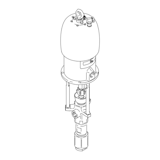
- Page 17 Service Model 237287 Shown Torque to 136–149 N.m (100–110 ft-lb) Torque to 196–210 N.m (145–155 ft-lb) Torque to 81–89 N.m (60–66 ft-lb) 04142B Fig. 6 308354...
- Page 18 Service DISPLACEMENT PUMP SERVICE If the assembly separates at joint B: Disassembly c. Unscrew the cylinder (9) and valve housing (18) from the outlet housing (7). Gently pull the When disassembling the pump, lay out all the removed cylinder and valve housing straight out of the parts in sequence, to ease reassembly.
- Page 19 Service Torque to 325–353 N.m (240–260 ft-lb). Lubricate. Torque to 190–217 N.m (140–160 ft-lb). 03794B Fig. 7 Torque to 271–298 N.m (200–220 ft-lb). 03793A Fig. 8 308354...
- Page 20 Service Reassembly 6. Lubricate the piston packings. Slide the displace- ment rod (1) and piston assembly down into the cylinder (9). The cylinder is symmetrical, so either 1. If it was necessary to remove the piston ball end may face up. Use a rubber mallet to drive the housing (10) from the displacement rod (1), clean rod into the cylinder, until the piston seat housing the threads of the rod and the ball housing.
- Page 21 Service Torque to 136–149 N.m (100–110 ft-lb). Torque to 325–353 N.m (240–260 ft-lb). Torque to 271–298 N.m (200–220 ft-lb). Lubricate. See Throat Packing Detail at left. Lips face up. See Piston Packing Detail at left. Lips face down. Torque to 190–217 N.m (140–160 ft-lb). Throat Packing Stack Detail (Displacement Pump 236470 Shown;...
- Page 22 Parts Part No. 237286 Pump, Series B Ref. Part No. Description Qty. 56:1 Ratio, with Reduced Icing 245112 AIR MOTOR, King, reduced icing Quiet King Air Motor For Model 237286 See 309348 for parts Part No. 245172 Pump, Series A 245111 AIR MOTOR, King 56:1 Ratio, with King Air Motor...
- Page 23 Parts Part No. 237287 Pump, Series A Ref. Part No. Description Qty. 28:1 Ratio, with Bulldog Air Motor 208356 AIR MOTOR, Bulldog See 307049 for parts 102Y 176529 LABEL, warning 105{ 190000 ROD, tie; 224 mm (8.82 in.) shoulder to shoulder; carbon steel 106{ 186925 NUT, coupling...
- Page 24 Parts Part No. 237280 Pump, Series A Ref. Part No. Description Qty. 17:1 Ratio, with Senator Air Motor 217540 AIR MOTOR, Senator See 307592 for parts 102Y 176529 LABEL, warning 105{ 190000 ROD, tie; 224 mm (8.82 in.) shoulder to shoulder; carbon steel 106{ 186925 NUT, coupling...
- Page 25 Parts Part No. 237290 Pump, Series A, with Ref. Part No. Description Qty. Viscount Hydraulic Motor 235345 HYDRAULIC MOTOR, Viscount Part No. 248817 Pump, Series A, with See 307158 for parts 190287 ADAPTER, connecting rod Viscount Hydraulic Motor 184596 ROD, tie; 315 mm (12.40 in.) shoulder to shoulder 186925 NUT, coupling...
- Page 26 Parts NOTE: The parts listed on this page are common to all Part displacement pumps covered in this manual. Refer to page Description 27 for the different packing configurations available. 189316 ROD, displacement; stainless steel 236582 PACKING NUT; stainless steel * These parts are included in Repair Kit 237172, which may 237182 HOUSING, outlet;...
- Page 27 Packing Kits Leather Packing Kit 237172, for Standard Displacement Pump 236470, Series A Part PISTON PACKINGS: THROAT PACKINGS: LIPS FACE UP LIPS FACE DOWN Description 184304 V-PACKING, throat; leather 184174 GLAND, throat, female; stainless steel 1 109304 V-PACKING, throat; PTFE 184224 GLAND, throat, male;...
-
Page 28: Ratio
Technical Data (Model 237286 Reduced Icing Quiet King Pump, Model 245173 Quiet King Pump, and Model 245172 King Pump) WARNING Be sure that all fluids and solvents used are chemically compatible with the Wetted Parts listed below. Always read the manufacturer’s literature before using fluid or solvent in this pump. -
Page 29: Mpa, 193 Bar (2800 Psi)
Technical Data (Model 237287 Bulldog Pump) WARNING Be sure that all fluids and solvents used are chemically compatible with the Wetted Parts listed below. Always read the manufacturer’s literature before using fluid or solvent in this pump. Ratio ............... 28:1 Maximum fluid working pressure . -
Page 30: Mpa, 117 Bar (1700 Psi)
Technical Data (Model 237280 Senator Pump) WARNING Be sure that all fluids and solvents used are chemically compatible with the Wetted Parts listed below. Always read the manufacturer’s literature before using fluid or solvent in this pump. Ratio ............... 17:1 Maximum fluid working pressure . -
Page 31: Mpa, 345 Bar (5000 Psi)
Technical Data (Model 237290 and 248817 Viscount II Pumps) WARNING Be sure that all fluids and solvents used are chemically compatible with the Wetted Parts listed below. Always read the manufacturer’s literature before using fluid or solvent in this pump. Category Data Ratio... -
Page 32: Mpa, 99 Bar
Technical Data (Model 237290 and 248817 Viscount II Pump) Performance Charts To find Fluid Outlet Pressure (psi/MPa/bar) at a specific fluid flow To find Pump Hydraulic Oil Consumption (gpm or lpm) at a specific (lpm/gpm) and operating hydraulic pressure (psi/MPa/bar): fluid flow (lpm/gpm): 1. - Page 33 Dimensions Mounting Hole Layout Model 237287 Shown 94.28 mm (3.712 in.) 101.6 mm (4.0 in.) 94.28 mm (3.712 in.) 50.8 mm (2.0 in.) Three M16 x Holes 11.1 mm (0.437 in.) 88 mm DIA (4) (3.464 in.) 0653 04143B Pump Model 237280 1138 mm 590 mm...
- Page 34 With the exception of any special, extended, or limited warranty published by Graco, Graco will, for a period of twelve months from the date of sale, repair or replace any part of the equipment determined by Graco to be defective.
Need help?
Do you have a question about the Dura-Flo 900 Series and is the answer not in the manual?
Questions and answers