Graco ToughTek S340e Operation, Repair, And Parts
Portable stucco pump
Hide thumbs
Also See for ToughTek S340e:
- Operation, repair, and parts (38 pages) ,
- Instructions manual (34 pages) ,
- Operation, repair, and parts (38 pages)
Table of Contents
Advertisement
Quick Links
Operation, Repair, and Parts
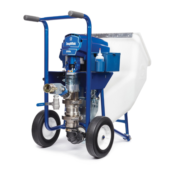
ToughTek
Stucco Pump
Electric sprayer for water-based stucco base, finish coat materials, and Exterior Insulation
and Finish Systems (EIFS). For professional use only. Not approved for use in explosive
atmospheres or hazardous locations.
Important Safety Instructions
Read all warnings and instructions in this manual
and in related manuals before using the equipment.
Save all instructions.
For models and related manuals, see page 3.
600 psi (4.13 MPa, 41.3 bar) Maximum Fluid Working Pressure.
®
S340e Portable
3A3437G
EN
Advertisement
Table of Contents

Related Manuals for Graco ToughTek S340e


Summary of Contents for Graco ToughTek S340e
- Page 1 Operation, Repair, and Parts ® ToughTek S340e Portable 3A3437G Stucco Pump Electric sprayer for water-based stucco base, finish coat materials, and Exterior Insulation and Finish Systems (EIFS). For professional use only. Not approved for use in explosive atmospheres or hazardous locations. Important Safety Instructions Read all warnings and instructions in this manual and in related manuals before using the equipment.
-
Page 2: Table Of Contents
Technical Specifications ....37 Graco Standard Warranty ....38... -
Page 3: Models
230V, 10A, 50/60 Hz, 1ɸ Europe, Asia, Australia 25A306† † All 230V pumps include a Europe adapter and Australia adapter cord set. Related Manuals Manuals are available at www.graco.com Manual in Description English 3A3438 Pole Spray Applicator 3A3653 HTX Finish Coat Applicator 3A3112 ®... -
Page 4: Replacement Parts And Accessories
Replacement Parts and Accessories Replacement Parts and Accessories Accessories 17G554 KIT, remote switch, control box 17W604 KIT, remote switch, (switch with attached 100 ft. cable) 17W829 KIT remote switch, extension cord (110 ft.) 248515 KIT, sponge ball, 30 mm for 25 mm (1.0 in.) dia. hose (Qty. 5) 25A227 KIT, sponge ball, 40 mm for 35 mm (1-3/8 in.) dia. - Page 5 Replacement Parts and Accessories Hopper 17J707 KIT, F340e, hopper with cover 17J709 KIT, F340e, hopper, bracket 17J812 KIT, F340e, Stop, bracket 17J710 KIT, F340e, adjustable latch 17J708 KIT, F340e, stop, brackets Motor and Driver 17J702 KIT, F340e, MCM, 120V 25C512 KIT, F340e, MCM, 120V, UK 17J755 KIT, F340e, MCM, 230V...
-
Page 6: Warnings
Warnings Warnings The following warnings are for the setup, use, grounding, maintenance, and repair of this equipment. The exclamation point symbol alerts you to a general warning and the hazard symbols refer to procedure-specific risks. When these symbols appear in the body of this manual or on warning labels, refer back to these Warnings. Product-specific hazard symbols and warnings not covered in this section may appear throughout the body of this manual where applicable. - Page 7 Warnings WARNING EQUIPMENT MISUSE HAZARD Misuse can cause death or serious injury. • Do not operate the unit when fatigued or under the influence of drugs or alcohol. • Do not exceed the maximum working pressure or temperature ratings of the lowest rated system component.
- Page 8 Warnings WARNING SKIN INJECTION HAZARD High-pressure fluid from dispensing device, hose leaks, or ruptured components will pierce skin. This may look like just a cut, but it is a serious injury that can result in amputation. Get immediate surgical treatment. •...
-
Page 9: Component Identification
Component Identification Component Identification Overview Component Identification Table Hopper Pin Electric Motor Motor Power Switch Pump Lower Hopper Latch Fluid Drain/Purge Valve Remote Pump Control Switch (optional) Fluid Outlet Flow Adjustment Knob Hopper Control Board Status Light 3A3437G... -
Page 10: Motor Power Switch
Component Identification Motor Power Switch Connect Hoses and Applicator The motor power switch (S) must be in the ON position • Before connecting hoses/applicator, inspect for for the sprayer to pump material. damage or wear to both the hose/applicator and cam lock fittings. -
Page 11: Install The Remote Switch (Optional)
Component Identification Prime with Material Install the Remote Switch (Optional) The remote switch is an additional accessory kit and does not come with models 25A300 and 25A304. The kit part number is 17G554. See manual 3A3112 for remote switch installation and replacement. NOTE: Use zip-tie (Z) to install the remote switch to the NOTICE hose or pole spray applicator (follow the illustrations... -
Page 12: Grounding
Grounding Grounding Extension Cords • Use only a 3-wire extension cord that has a grounding plug and a grounding receptacle that accepts the plug on the product. The equipment must be grounded to reduce the risk of static sparking and electric shock. Electric or static •... -
Page 13: Setup
Grounding Setup 5. Attach check valve (optional). Remove fluid outlet assembly (F). Attach check valve (M) to pump fluid outlet. Attach fluid outlet assembly to check valve (M) outlet. To avoid tipping over, ensure cart is on a flat and level surface. -
Page 14: Flush
Flush Flush 3. Place applicator outlet in a waste container. The waste container must be large enough to hold all dispensed material. NOTICE Failure to flush prior to material curing in the system will result in damage to system and may require replacement of all system parts in contact with the material. - Page 15 Flush 11. Circulate clean water: 14. Drain remaining water from system: a. Fill the system hopper with clean water. a. Place a drain pan beneath pump lower inlet connection. b. Turn the motor power switch (S) to ON to begin circulating water.
-
Page 16: Prime With Water
Prime with Water Prime with Water 6. Run the clean-out ball(s) to coat the inside of the hoses. a. Remove the applicator from the end of the hose. NOTICE b. Remove the hose inlet from the pump outlet and place a hose clean-out ball within the hose inlet. To prevent material curing in the system, never load mate- rial into a dry system. -
Page 17: Mix The Material
Mix the Material Mix the Material Prime with Material Always follow the material manufacturer’s instructions for the material being sprayed. Material must be thoroughly mixed to a smooth consistency before loading it in the hopper. NOTE: For stucco base and base coats, it is NOTICE recommended to use a standard 8 oz. -
Page 18: Spray
Spray Spray 5. Turn the motor power switch (S) to ON. Prevent Pack-Out To avoid “packing out” the pump or hose: • Use the lowest pressure and largest nozzle size that provides an acceptable spray pattern. This will also result in seals and wear parts lasting much longer. •... -
Page 19: Spray Adjustments (Pole Spray Applicator)
Spray Adjustments (Pole Spray Applicator) Spray Adjustments (Pole Spray Applicator) Test the spray pattern on cardboard. Hold the applicator 18 - 30 in. (45 - 76 cm) away from the surface. Use this spraying distance for most applications. Adjust fluid flow until material flow is adequate. Adjust the applicator air ball valve (CB) to achieve a uniform round spray pattern. -
Page 20: Spray Adjustments
™ Spray Adjustments (HTX Applicator) ™ Spray Adjustments (HTX Applicator) The standard applicator adjustment is to fully open the air assist valve (DF) while adjusting the needle valve (DE) for the minimum air flow necessary for a good pattern. Air bleeds from the applicator nozzle whenever the air assist valve (DF) is open. -
Page 21: Fluid Drain/Purge Valve
Fluid Drain/Purge Valve Fluid Drain/Purge Valve 1. Turn the flow adjustment knob (H) counterclockwise until it stops. 2. Turn the motor power switch (S) OFF. 3. Remove the applicator tip and the tip retainer. 4. Hold the applicator firmly against a waste container. To avoid injury from splashing fluid, never open a cam-lock hose or applicator fitting while there is pressure in the fluid line. -
Page 22: Hopper Removal
Hopper Removal Hopper Removal NOTE: If the hopper elbow needs to be thoroughly cleaned, rotate knob (K) to loosen the clamp between the elbow and the hopper. Remove and clean the elbow. NOTE: To re-install the hopper, follow the steps above in reverse order. -
Page 23: Maintenance
Maintenance Maintenance Daily Maintenance Corrosion Protection NOTICE To prevent rust, never leave water or water-based fluid in pump overnight. 1. Flush the system, see Flush, pg. 14. 2. Clean hopper with a scrub pad. It is recommended NOTICE that you clean the outside of the sprayer using a Material left on the throat seal can dry out and dam- cloth and water. -
Page 24: Troubleshooting
Troubleshooting Troubleshooting 2. Check all possible problems, causes, and solutions listed below before disassembling pump. For troubleshooting and repair questions, please contract your distributor. 1. Follow Pressure Relief Procedure, pg. 21. Mechanical/Fluid Flow Problem Cause Solution Displacement pump operates, Piston ball check not sealing properly Service the piston ball check. -
Page 25: Electrical
Troubleshooting Problem Cause Solution Material is too thick to push Hose is too restrictive Thin and mix material thoroughly to a lower viscosity. through the hose without Use a pump system priming fluid (slime). Wet out the packing out system. Use a larger diameter hose. - Page 26 Troubleshooting Problem Cause Solution Turn the motor power switch (S) to OFF and unplug Control board status light Connections above the motor may be loose the sprayer. blinks 15 times repeatedly or damaged Remove the motor shroud. Disconnect the motor controls and inspect for damage at the connections.
-
Page 27: Repair
Repair Repair Perform the procedure below to replace the entire pump lower with a new or different pump lower. 1. Perform the Pressure Relief Procedure, pg. 21. 2. Disconnect the hopper, material hose, and power. NOTE: When reinstalling the pump lower, the jam nut 3. -
Page 28: Replace Pump Components
Repair Replace Pump Components Remove the pump lower (6a - 17G864) before replacing any pump components. For a list of available pump lower kits, see the list on the following page. 3A3437G... - Page 29 Pump Components Parts List Pump Components Parts List Ref. Part Description Ref. Part Description 17G221 HOUSING, inlet 17G220 HOUSING, outlet † SEA, carbide, valve, inlet 17G859 NUT, jam, black † O-RING, 50 mm x 2.5 mm 17G865 KIT, bearing, seal throat, 3-pack 15H833†...
-
Page 30: Parts
Parts Parts S340e Systems 3A3437G... - Page 31 Parts Ref. Part Description Qty. Ref. Part Description Qty. SCREW, cap, hex hd 17J707 HOPPER, 340e, with cover 125112 SCREW, cap, btn hd, 5/16 in. 17J709 BRACKET, 340e, painted, hopper † NUT, hex, flange head 17J812 BRACKET, stop, adjustable, 340e 100527 WASHER, plain 17J710...
- Page 32 Parts S340e Systems (continued) 3A3437G...
- Page 33 Parts Ref. Part Description Qty. Ref. Part Description Qty. 191824 WASHER, space CART, 340e, painted 111841 WASHER, plain, 5/8 † MODULE, 340e, motor control, 120V 101242 RING, retaining, ext. † MODULE, 340e, motor control, 120V, 100527 WASHER, plain 111040 NUT, lock, insert, nylock, 5/16 in. †...
- Page 34 Parts Driver and Motor 3A3437G...
- Page 35 Parts Ref. Part Description Qty. Ref. Part Description Qty. 119250 SCREW, shoulder MOTOR, electric 118444 SCREW, mach, slot, hex wash hd GEAR, combination 276980 GROMMET, cover HOUSING, drive SCREW, cap, hex hd 15D088 FAN, motor 76 192840 LABEL, warning 278075 BRACKET, wire 15C753 SCREW, mach, hex wash hd...
- Page 36 Control Box Control Box Ref. Part Description Qty. Ref. Part Description Qty. 16U215 SCREW, phillips, pan hd, plastite CONTROL, board, 50 amp 114391 SCREW, grounding COVER, control, ultra, std LABEL, control, F340e, Proguard 116167 KNOB, potentiometer GASKET, housing, motor control, 256219 POTENTIOMETER F340e...
-
Page 37: Technical Specifications
Technical Specifications Technical Specifications Toughtek S340e Sprayer Metric Maximum fluid working pressure 600 psi 4.1 MPa, 41 bar Stroke length 2.25 in. 57 mm Maximum pump speed (Do not exceed maxi- 150 cycles per minute mum recommended speed of fluid pump to... -
Page 38: Graco Standard Warranty
With the exception of any special, extended, or limited warranty published by Graco, Graco will, for a period of twelve months from the date of sale, repair or replace any part of the equipment determined by Graco to be defective.
Need help?
Do you have a question about the ToughTek S340e and is the answer not in the manual?
Questions and answers