Fukuda Denshi DYNASCOPE 8000 Series Service Manual
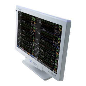
Central monitor
Hide thumbs
Also See for DYNASCOPE 8000 Series:
- Service manual (274 pages) ,
- Operation manual (252 pages) ,
- Maintenance manual (154 pages)


Need help?
Do you have a question about the DYNASCOPE 8000 Series and is the answer not in the manual?
Questions and answers
What does the blue circle with an exclamation point in the center, of the sp02 section mean?