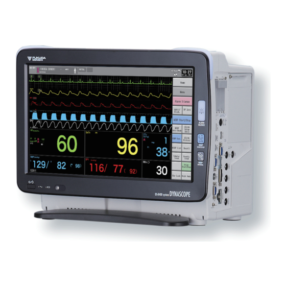
Fukuda Denshi DYNASCOPE 8000 Series Service Manual
Patient monitor
Hide thumbs
Also See for DYNASCOPE 8000 Series:
- Operation manual (252 pages) ,
- Service manual (219 pages) ,
- Maintenance manual (154 pages)

Subscribe to Our Youtube Channel
Related Manuals for Fukuda Denshi DYNASCOPE 8000 Series


Summary of Contents for Fukuda Denshi DYNASCOPE 8000 Series
- Page 1 Series Service Manual Patient Monitor Ver. 03 Maintenance Manual * Before installation/maintenance, read this service manual thoroughly. * After reading this service manual, store it in a safe place.
- Page 2 2017 Fukuda Denshi Co., Ltd. © No part of this document may be reproduced or transmitted in any form without the prior written permission of Fukuda Denshi Co., Ltd. If this manual has pages missing or out of order, contact Fukuda Denshi for replacement.
- Page 3 Revision History Model Name DS-8400 System Service Manual Edition Revised Items Reason of the Revision Date - New Edition 2017.06...
-
Page 5: Table Of Contents
Preface Thank you for purchasing this product. Before using this product, read the following precautions to make sure the product is used correctly and safely. About the Safety Precautions ································ ii The Meaning of Each Safety Precaution ················ ii ... -
Page 6: About The Safety Precautions
About the Safety Precautions The Meaning of Each Safety Precaution Read this manual thoroughly before use to ensure correct and safe use of the product. Be sure to follow the precautions indicated below, as these are important messages related to safety. Indicates an imminently hazardous situation which, if not avoided, will result in D A N G E R death or serious injury. - Page 7 Super Unit: HS-8000 Series Contents of the Label Warning Label Attached to the Equipment (HS-8312) Contents of the Label ...
-
Page 8: Graphic Symbols
Graphic Symbols Refer to the following for the meaning of the symbol indicated on the equipment. Symbol Description Follow operating instructions (Warning); indicated in blue. Failure to follow operating instructions could place the patient or operator at risk. ... - Page 9 Symbol Description WEEE (Waste Electrical and Electronics Equipment) Indicates a separate collection for electrical and electronic equipment. Alarm Silence NIBP Start/Stop NIBP Periodic Measurement Lock Unlock...
-
Page 10: Equipment
Precautions for Safe Operation of Medical Electrical Equipment CAUTION Users should have a thorough knowledge of the operation before using this equipment. Do not use the equipment in an environment where protective earth and wiring is questionable. ... - Page 11 Precaution when Equipment Failure Occurs If the equipment is damaged and in need of repair, label the unit "OUT OF ORDER" and contact Fukuda Denshi. Precaution about Disassembling/Remodeling the Equipment Do not disassemble or remodel the equipment. ...
-
Page 12: Precautions About The Maintenance
Precautions about the Maintenance WARNING Never open the housing while the equipment is in operation or connected to hospital grade outlet as it may result in electric shock. Precautions about Safety Check CAUTION For safe operation of the equipment, regular inspection and maintenance are required. Once a year, check all cables, devices, and accessories for damage, earth impedance, earth and leakage currents, and all alarm functions. -
Page 13: Precautions About The Network System
When interference or breakdown occurs in telemetry communication, the user is required to inform the zone manager and the overall manager of the problems. The Zone Manager and Overall Manager are to deal with the problem properly and/or contact their nearest Fukuda Denshi representative for service. -
Page 14: Precautions When Using With Other Equipment
If such event occurs, please disconnect the cardiac monitoring and diagnostic equipment, or follow the procedures described in the operation manual of the pacemaker. For more details, contact FUKUDA DENSHI personnel, your institution's professionals, or your pacemaker distributors. -
Page 15: Electrosurgical Instrument
Electrosurgical Instrument WARNING The monitoring system contains protection against interference generated by electrosurgical instruments. However, depending on the operating conditions, surgery site with respect to the location of ECG electrodes, ground plate attachment condition, or the type of instrument used, it may cause burn injury at the electrode site or noise on the ECG. -
Page 16: Precautions About Connections To Peripheral Devices
Fukuda Denshi. It is the user's responsibility to contact Fukuda Denshi to determine the compatibility and warranty status of any connection made to another manufacturer's equipment. -
Page 17: Precautions For Using The Equipment
Warnings about the System Do not connect any equipment or cable not authorized by Fukuda Denshi to any I/O connector. Also, do not connect any damaged equipment or cable. If done so by mistake, not only that the equipment cannot deliver its maximum performance, the equipment may be damaged and safety cannot be ensured. - Page 18 When a patient is receiving a photodynamic therapy, measuring SpO on a same site for a long duration may cause blisters from the irradiation light of the SpO sensor. Make sure to periodically change the sensor attachment site. ...
- Page 19 WARNING Warnings about the Gas Monitoring (MGU-800/810) Make sure to use only the specified Mindray Medical Sweden AB product. Be careful not to damage the water trap during operation as bacteria and/or mucus may contaminate the MGU- 800/810 series.
- Page 20 This equipment utilizes LED for the backlight. Since this LED deteriorates by the life cycle, the display may become dark, scintillate, or may not light by the long term use. In such case, contact Fukuda Denshi. This equipment is intended to be used for only one patient.
- Page 21 12-lead ECG. Moreover, waveforms may differ somewhat also in a supine position and a standing position (sitting position). Fukuda Denshi recommends to carry out the recording of the ECG by taking into consideration the waveform differences according to electrode positions or postures.
- Page 22 If irritation such as skin reddening appears with the sensor use, change the attachment site or stop using the sensor. Do not apply the sensor too tight. At the same time, check the blood flow constantly so that congestion is not generated at the peripheral site.
- Page 23 If the Equipment Status Alarm occurs or if you feel the unusual operation of the equipment, perform the inspections to confirm the safety or contact Fukuda Denshi. If the transducer get disconnected, pay attention that the metal part of the transducer does not get in touch with any metal parts of the bed or any conductive parts.
- Page 24 ® Microstream EtCO sampling tubes are designed for single patient use, and are not to be reused. Do not attempt to clean, disinfect, sterilize or flush any part of the sampling tube as this can cause damage to the monitor or lead to cross-infection.
- Page 25 If the accuracy check is performed using a low pressure gas, the accuracy of gas measurement will be reduced. Make sure to perform the accuracy check using the specified calibration gas before its expiration date. If the error persists, refer to Fukuda Denshi. About the MGU-810 Series ...
- Page 26 The pressure tube and gas sampling lines of the flow sensor should always be routed from the patient circuit to the MGU-810 such a way as to avoid kinking. Flow sensors that have suffered damage to sensor head, tubing or tubing connector must not be used. ...
-
Page 27: Wired Network (Ds-Lanii/ Ds-Laniii)
Wired Network (DS-LANII/ DS-LANIII) WARNING Do not connect unspecified device to the wired network. Do not mix devices with DS-LANII and DS-LANIII setting in the same wired network. The network may cease and proper monitoring may not be possible. CAUTION ... -
Page 28: Wireless Network System
On the central monitor, the respiration waveform and RR value based on the RR/APNEA alarm source selected on the DS-8400 System will be displayed. The monitored RR and APNEA will be the same for the central monitor and the DS-8400 System. Wireless Network System DANGER ... -
Page 29: Precautions About The Ventilator Monitoring
If there are any questions regarding the sensor/relay cable use for SpO measurements of this equipment, please contact Fukuda Denshi. Precautions about the Masimo Model CAUTION ... -
Page 30: Precautions About Transportation
Precautions about Transportation CAUTION When transporting this equipment, pack it with specified packing materials. Also, transport it under appropriate environment condition. "Chapter 2 Specification") Monitoring after Power Failure When the power failure is less than 30 seconds, monitoring will resume with the display mode and patient information unchanged. -
Page 31: Electromagnetic Compatibility
Electromagnetic Compatibility The performance of this equipment under electromagnetic environment complies with IEC 60601-1-2: 2007. CAUTION Do not use any unauthorized equipment or cables as they may not comply with the EMC standard. Precautions for Safe Operation under Electromagnetic Influence If any sorts of electromagnetic wave, magnetic field, or static electricity exist around the device, noise interference or malfunction of the device may occur.If any unintended malfunction or noise occurs during monitoring, check the electromagnetic influence and take appropriate countermeasures. -
Page 32: Emc Guidance
EMC Guidance This device complies with the Safety Standard IEC 60601-1-2: 2007. However, if portable transmitter or wireless LAN equipment is used extremely nearby, the electromagnetic influence may largely exceed the compliance level and may cause unexpected phenomenon such as noise interference on the waveform, etc. Also, if this equipment is installed close to, or stacked with other equipment, malfunction may occur. - Page 33 Compliance to the Electromagnetic Immunity (1) The DS-8400 System is intended for use in the electromagnetic environment specified below. The customer or the user of the DS-8400 System should assure that it is used in such an environment. Guidance and Manufacturer's Declaration - Electromagnetic Immunity IEC 60601-1-2 Electromagnetic Environment -...
- Page 34 Compliance to the Electromagnetic Immunity (2) The DS-8400 System is intended for use in the electromagnetic environment specified below. The customer or the user of the DS-8400 System should assure that it is used in such an environment. Guidance and Manufacturer's Declaration - Electromagnetic Immunity IEC 60601-1-2 Compliance...
- Page 35 Recommended Separation Distances between Portable and Mobile RF Communications Equipment and the DS-8400 System The customer or the user of the DS-8400 System can help prevent electromagnetic interference by maintaining a minimum distance between portable and mobile RF communications equipment (transmitters) and the DS-8400 System as recommended below, according to the maximum output power of the communications equipment.
- Page 36 xxxii...
- Page 37 C ontents 0 B 0 B Preface Chapter 1 General Description This chapter describes the outline of the equipment. This chapter describes the specification and Chapter 2 Specification performance of the equipment. Chapter 3 This chapter describes the names of parts and their Names of Parts and Their functions of the equipment.
- Page 38 Preface Chapter 2 Specification About the Safety Precautions ··································· ii Main Unit: DSC-8400 Series ···························· 2-2 The Meaning of Each Safety Precaution ················ ii Transport Monitor: DS-8007 and DSA-82 ············ 2-3 Warning Labels Attached to the Unit ····················· ii Display Unit: LC-8018TC/LC-8016TC ················· 2-4 Graphic Symbols ·············································...
- Page 39 Chapter 5 Wiring Diagram Chapter 8 Software Upgrade Procedure Main Unit DSC-8400 ······································ 5-2 Software Upgrade ··············································· 8-2 Installation procedure 1 (Backup or Restore Data) 8-2 Installation procedure 2 (When you do not need to Chapter 6 Spare Parts List backup or restore data) ···································...
- Page 40 Chapter 10 Maintenance DIP Switch / Rotary Switch Setup ························ 10-2 DIP Switch Setup ········································· 10-2 Rotary Switch Setup ····································· 10-3 Test menu ······················································ 10-4 How to display Test Menu ····························· 10-4 Test Menu Description ·································· 10-5 Test Menu Details ········································ 10-7 Storage (Equipment and Recording Paper) ···········...
- Page 41 Chapter 1 General Description This chapter describes the outline of this equipement. Composition of the System ································ 1-2 Features ·························································· 1-4...
- Page 42 Composition of the System The DS-8400 system is composed of Display Unit (LC-8016TC/LC-8018TC), Main Unit (DSC-8410), Super Unit (HS-8000 series/DS-8007 series), Multigas Unit (MGU-800 series/MGU-810 series), Recorder Unit (HR-800), expansion modules and Input Box (IB-8004). Lineup of Main Unit Model Type External Monitor Output Extended Display Unit LAN (TCP/IP)
- Page 43 Lineup of Adapter Model Type Remarks HSA-80 Adapter for HS-8000 series (Connects to the patient monitor with module connection cable.) Adapter for HS-8000 series (Connects to the patient monitor by sliding on the rail at the rear side HSA-81 of the patient monitor.) DSA-82 Adapter for DS-8007 series (Connects to the patient monitor with module connection cable.) Lineup of Multigas Unit...
- Page 44 Features Various displays such as enlarged numeric data, trend, or ventilator can be selected according to monitoring conditions. The operation can be performed with the touch panel. Also, frequently used keys can be programmed as user key. It is possible to connect two types of display units in addition to the main display unit to extend the display. ...
- Page 45 By using the optional Recorder Unit (HR-800), the measurement data can be printed. By connecting the optional Multigas Unit (MGU-800/810 series), CO concentration, anesthetic gas concentration, O measurement, N O concentration can be measured. The following anesthetic agents can be measured.
- Page 47 Chapter 2 Specification This chapter describes the specification and performance of this equipment. Main Unit: DSC-8400 Series ···························· 2-2 Transport Monitor: DS-8007 and DSA-82 ············ 2-3 Display Unit: LC-8018TC/LC-8016TC ················· 2-4 Super Unit: HS-8312N/8312M and HSA-80/HSA-81 ············ 2-5 Expansion Unit : MGU-800/810 Series and HR-800 ···················...
- Page 48 Main Unit: DSC-8400 Series Size 360(W) x 310(H) x 255(D) mm (not including the protrusion) Weight 7.5 kg (not including the accessory) Environmental Conditions Operating Temperature 10°C to 40°C Operating Humidity 30% to 85% (non-condensing) Operating Atmospheric 70 kPa to 106 kPa Pressure Transport/Storage -10°C to 60°C...
- Page 49 Operation Time 1.5 hours or more (at 25°C, DSC-8410, LC-8018TC, power saving mode, DS-8007 standard measurement, continuous NIBP measurement of 15 min.) Charging Time 2.5 hours (rapid charge-standby), 5 hours (normal charge-operation) Usable Life 6 years According to self-certification Transport Monitor: DS-8007 and DSA-82 Size DS-8007 200 (W) mm x 108 (D) mm x 185 (H) mm (not including the protrusion)
- Page 50 Waterproof/Dustproof DS-8007 Main Unit: IP32 Only when temperature connector cover, USB memory slot cover, CO I/F connector cover, button cover, battery cover is attached. Protection against Ignition of Not provided Flammable Gas Power Supply Voltage DSA-82: DC18V (Supplied from DSC-8410 main unit) Usable Life 6 years According to self-certification.
- Page 51 Protection against Ignition of Not provided Flammable Gas Power Supply Voltage DC 18 V (Supplied from DSC-8410 main unit) Usable Life 6 years According to self-certification Super Unit: HS-8312N/8312M and HSA-80/HSA-81 Size HS-8312N/8312M 85 (W) mm x 100 (H) mm x 200 (D) mm (not including the protrusion) HSA-80 85(W) mm x 68(H) mm x 188(D) mm (not including the protrusion) HSA-81...
- Page 52 Degree of protection against ECG /RESP (Impedance), SpO , SpCO , SpMet , SpHb , TEMP, BP, CO: Type CF Applied Part electric shock NIBP: Type BF Applied Part *: For HS-8312M only Protection against Ignition of Not provided Flammable Gas Power Supply Voltage HSA-80: DC 18 V (Supplied from DSC-8410 Main Unit)
- Page 53 EMC Standard IEC 60601-1-2: 2007 (Medical Electrical Equipment- Part 1-2: General Requirements for Safety – Electromagnetic Compatibility – Requirements and Tests) Type of protection against Class I Equipment (During AC power operation) electric shock Internally Powered Equipment (During battery operation) Degree of protection against Respiration Gas (MGU-800/810): Type BF Applied Part electric shock...
- Page 54 Type of protection against Class I Equipment (During AC power operation) electric shock Internally Powered Equipment (During battery operation) Degree of protection against TEMP, BP, CO (HM-800/HM-801): Type CF Applied Part electric shock BIS: Type BF Applied Part (When connected to BISx) , SpCO, SpMet, SpHb (HG-810): Type CF Applied Part (HG-820) : Type CF Applied Part Protection against Ignition of...
- Page 55 EMC Standard IEC 60601-1-2: 2007 (Medical Electrical Equipment- Part 1-2: General Requirements for Safety – Electromagnetic Compatibility – Requirements and Tests) Type of protection against Class I Equipment (During AC power operation) electric shock Internally Powered Equipment (During battery operation) Degree of protection against : Type BF Applied Part electric shock...
- Page 56 EMC Standard IEC 60601-1-2: 2007 (Medical Electrical Equipment- Part 1-2: General Requirements for Safety- Electromagnetic Compatibility -Requirements and Tests) Type of protection against Class I Equipment (DS-8007 System)/Internally Powered Equipment (DS-8007 System) electric shock Degree of protection against : Type BF Applied Part electric shock Protection against Ignition of Not provided...
- Page 57 Type of protection against Class I Equipment (During AC power operation) electric shock Internally Powered Equipment (During battery operation) Protection against Ignition of Not provided Flammable Gas Power Supply Voltage DC 18 V (Supplied from DSC-8410 Main Unit) Usable Life 6 years According to self-certification BISx I/F Unit: HBX-800...
- Page 58 Usable Life 6 years According to self-certification Performance This section states the performance of the DS-8400 system. The EMC essential performance is indicated with Display Panel Display Device 18.5 inch TFT Color LCD (LC-8018TC) 15.6 inch TFT Color LCD (LC-8016TC) Resolution 18.5 inch: 1366 pixel ×...
- Page 59 Lead Type Wired 3, 4, 5, 10-electrode Frequency Characteristic 150Hz/40Hz/15Hz (3, 4, 5, 10-electrode) (HS-8000) Input impedance 2.5 MΩ or above Maximum Input Voltage 10 mVp-p Polarization Voltage ±825 mV or above Common Mode Rejection 90 dB or above Ratio HR Measurement Range Adult: 0, 12 bpm to 300 bpm Neonate: 0, 30 bpm to 300 bpm...
- Page 60 Time to ALARM for Ventricular Tachycardia 1 mVpp, 206 bpm: tachycardia Range 7.3 sec. to 8.1 sec., Average 7.6 sec. Ventricular Tachycardia 2 mVpp, 206 bpm: Range 7.4 sec. to 8.2 sec., Average 7.7 sec. Ventricular Tachycardia 0.5 mVpp, 206 bpm: Range 8.5 sec.
- Page 61 Current 100 μA and below (at 33.3 kHz±5%) Measurement Range 0, 4 Bpm to 150 Bpm Measurement Accuracy ±3 Bpm Temperature Measurement Method Thermistor Method Probe 400 only Measurement Range 0°C to 45°C Measurement Accuracy ±0.2°C at 25°C to 45°C Outside above range ±0.4°C No.
- Page 62 Masimo Unit Measurement Method 2 Wavelength Pulse Wave Method Masimo LNOP/LNCS Sensor Wavelength: Approx. 660 nm (red light) Approx. 905 nm (infrared light) Output: 15 mW and below Masimo Rainbow Sensor Wavelength: 12 different wavelengths are used within the range of 620 nm to 1270 nm Output: 25 mW and below Measurement Range 1%SpO...
- Page 63 Minimum Display Unit 0.1 ml/dL Pulse Rate Measurement Range 26 bpm to 239 bpm Measurement Accuracy ± 3 bpm when 26 bpm to 239 bpm (without body motion) Measurement Response 7 levels Time 2 to 4 sec., 4 to 6 sec., 8 sec., 10 sec., 12 sec., 14 sec., 16 sec. (averaging duration) The SpO measurement accuracy is determined based on the values of the ...
- Page 64 Error of Cuff Pressure Within ±3 mmHg Display Measurement Error ±10 mmHg (including simulator) PR Measurement Range 40 bpm to 240 bpm PR Accuracy ±5% Deflation Speed 5±1 mmHg/sec. (Quick Measurement OFF) 10±2 mmHg/sec. (Quick Measurement ON) Safety Mechanism Adult: 300 mmHg and below Child: 210 mmHg and below Neonate: 150 mmHg and below (Carbon Dioxide Concentration)
- Page 65 0 mmHg to 38 mmHg: ± (2 mmHg + 0.04 x displayed value) 39 mmHg to 99 mmHg: ± { 0.09 x displayed value + 0.08 x (displayed value - 39 mmHg) } RR Measurement Range 0 Bpm to 150 Bpm RR Measurement Accuracy 0 Bpm to 70 Bpm: ±1 Bpm 71 Bpm to 120 Bpm: ±2 Bpm...
- Page 66 Spectral Edge Frequency Measurement Range 0.5 Hz to 30 Hz Total Power (TOTPOW) Measurement Range 40 dB to 100 dB Waveform Display Scale ±25μV, ±50μV, ±100μV, ±250μV ±10% Frequency Characteristic Filter ON 2.0 Hz to 70 Hz, AC Filter ON (50 Hz or 60 Hz) Filter OFF 0.25 Hz to 100 Hz, AC Filter OFF MGU-800/MGU-810...
- Page 67 : MGU-801P/MGU-811P 0 to 25[vol%]: ±1[vol%] 25 to 80[vol%]: ±2[vol%] 80 to 100[vol%]: ±3[vol%] Volatile Halothane, enflurane, and isoflurane Anesthetic 0 to 1[vol%]: ±0.15[vol%] 1 to 5[vol%]: ±0.2[vol%] Sevoflurane 0 to 1[vol%]: ±0.15[vol%] 1 to 5[vol%]: ±0.2[vol%] 5 to 8[vol%]: ±0.4[vol%] Desflurane 0 to 1[vol%]: ±0.15[vol%] 1 to 5[vol%]: ±0.2[vol%]...
- Page 68 Threshold Volatile Primary 0.15[vol%] (Full Accuracy) Anesthetic 0.4[vol%] (during warm-up) For halothane, add 0.1[vol%] to above value. Secondary 0.3[vol%] (Full Accuracy) 0.5[vol%] (during warm-up) If primary agent is larger than 10[vol%], 5% of primary gas level. (10% for isoflurane) For halothane, add 0.1[vol%] to above value. Flow Rate 70 mL/min to 200 mL/min ±10 mL/min or ±10%, whichever is greater...
- Page 69 Measurement Range: 0 cmH O/L/s to 40 cmH O/L/s (Adult, Pediatric*) Peak, Plateau, PEEP, and Mean Pressure [cmH Measurement Range: -20 cmH O to 100 cmH O (Adult, Pediatric*) I:E Ratio Measurement Range: 1:4.5 to 2:1 (Adult, Pediatric*) Conditions of Use for Stated Accuracy Respiration Rate (RR): 4 Bpm to 35 Bpm (Adult), 4 Bpm to 50 Bpm (Pediatric*) I:E Ratio: 1:4.5 to 2:1 (Adult, Pediatric*) Intubation Tube: 5.5 mm to 10 mm (Adult), 3 mm to 6 mm (Pediatric*)
- Page 70 QRS Synchronization Output Output Waveform Square Wave (Positive/negative logic can be selected.) Output Voltage +4.3 V to +5.0 V (High Level) +0.3 V and below (Low Level) Synchronized Signal Width 100ms/60ms/20ms (selectable) Delay Time 35 ms and below (when the "Filter" setting is [Monitor] or [Diag.]) Output Impedance Open Collector Output (with +5 V 500Ω...
- Page 71 Chapter 3 Names of Parts and Their Functions This chapter explains the name of parts and their functions. Main Unit: DSC-8400 series ·································· 3-2...
- Page 72 Main Unit: DSC-8400 series Front Side 1 Display Unit Attaching Position Attaches the display unit (LC-8018TC/LC-8016TC). 2 Display Unit Connector Connects the display unit. Rear Side 1 HLX Fixing Position Fixes the Telemetry Transmitter Module (HLX-801). 2 HTC Fixing Position Fixes the Bidirectional Wireless Communication Module (HTC-702).
- Page 73 Right Side 1 Super Unit Connector Connects the specified equipment. 2 Module Connector Connects the specified equipment. 3 Super Unit Release Lever Releases the Super Unit from the main unit. Left Side The illustration shown on right is when the optional CC-84 and HR-800 are installed.
- Page 75 Chapter 4 Operational Description This chaper describes the outline of this equipment. Main Unit (DSC-8400) ···················································· 4-2 Circuit Description of Main CPU Board (PCB-7673) ·············· 4-2 Circuit Description of Mother Board (PCB-7674) ················· 4-21 Circuit Description of Memory Board (PCB-7675) ················ 4-25 Power Board (PCB-7676) ···············································...
- Page 76 Main Unit (DSC-8400) The diagram below explains the block diagram of the DSC-8400 and its function. Circuit Description of Main CPU Board (PCB-7673) The Main CPU Board controls, displays, and records the monitor. The input signal operation of the touch panel, remote control, etc are processed by the CPU and then the display of the monitor or each measurement condition will change.
- Page 77 RTC (Real Time Clock) An IC specified to clocking. Similar to the SRAM, it works receiving power supply from the backup battery for a long time while the power supply is turned off. When the power supply is turned on, it receives power from the external power supply.
- Page 78 ● External Connection CF-CARD connector (CN1801) Signal Signal Remarks Remarks Name Name Signal GND /CD1 Card Detect 1 Card Data D3 Card Data D11 Card Data D4 Card Data D12 Card Data D5 Card Data D13 Card Data D6 Card Data D14 Card Data D7 Card Data D15 Chip Enable 1...
- Page 79 DS-LANII connector (CN1702) 5Pin 8Pin 10Pin 2Pin 4Pin 7Pin 1Pin 9Pin 3Pin 6Pin Signal Name Remarks Signal Level 10BASE-T / Transmission data 100BASE-TX 10BASE-T / Transmission data 100BASE-TX 10BASE-T / Reception data 100BASE-TX Not connected Not connected 10BASE-T / Reception data 100BASE-TX RESERVED Reserved...
- Page 80 I/O Connector (CN502) Signal Name Remarks Signal Level +5 V Power Differential signal- Differential signal+ UNIT-LINK Connector (CN2101) Signal Name Remarks Signal Level TX1+ Transmission data 1+ RS-485 RX1+ Reception data 1+ RS-485 TX2+ Transmission data 2+ RS-485 RX2+ Reception data 2+ RS-485 +18 V Power Supply +18 V Power Supply...
- Page 81 Display Unit Connector (CN1201) Signal Name Remarks Signal Level GND_P Power Supply GND Odd number differential pixel DA0- LVDS data Odd number differential pixel DA0+ LVDS data GND_L Odd number differential pixel DA1- LVDS data Odd number differential pixel DA1+ LVDS data Power Supply+18 V...
- Page 82 Even number differential pixel DB1+ LVDS data Power Supply+18 V Even number differential pixel DB2- LVDS data Even number differential pixel DB2+ LVDS data GND_L Even number differential pixel DB3- LVDS data Even number differential pixel DB3+ LVDS data 3.3V_BUZZER Display unit buzzer power /DISP_INST Display unit start mode switch...
- Page 83 ● Internal connector CPU Main Power Supply Connector (CN1) Signal Name Remarks Signal Level Power Supply Input +18V Power Supply Input +18V Temperature Sensor Connector in Housing (CN201) Unused Signal Name Remarks Signal Level Applied voltage in temperature sensor Output current in temperature TMP2 sensor * This connector is not used for DSC-8400.
- Page 84 Display Unit I/F Connector (CN1202) Signal Name Remarks Signal Level Display Unit Power Supply POW_DISP_EN Control Signal Output CURR_18V_FFC External Current Detection Input External Voltage Detection VOLT_18V_FFC Input Voltage and Current Detection DISP84/85 External/Internal SW 3.3V_AUX 3.3 V Sub Power Supply /POWON2 Main Power Supply SW2 3.3V_AUX...
- Page 85 Signal Name Remarks Signal Level Differential serial receive data- LVDS Differential serial receive data+ LVDS Differential serial transmit data- LVDS Differential serial transmit data+ LVDS Even number differential pixel DB3- LVDS data Even number differential pixel DB3+ LVDS data 3.3V_BUZZER Display unit buzzer power Display unit reset /RESET_DISP...
- Page 86 CF Card Expansion Connector (CN1802) Signal Name Remarks Signal Level BF0_A[1] IP Address BF0_A[3] Address [3] BF0_A[5] Address [5] BF0_A[7] Address [7] BF0_A[9] Address [9] BF0_A[11] Address [11] BF0_A[13] Address [13] BF0_A[15] Address [15] BF0_A[17] Address [17] BF0_A[19] Address [19] BF0_A[21] Address [21] BF0_A[23]...
- Page 87 continued Signal Name Remarks Signal Level BF0_A[0] IP Address BF0_A[2] Address [2] BF0_A[4] Address [4] BF0_A[6] Address [6] BF0_A[8] Address [8] BF0_A[10] Address [10] BF0_A[12] Address [12] BF0_A[14] Address [14] BF0_A[16] Address [16] BF0_A[18] Address [18] BF0_A[20] Address [20] BF0_A[22] Address [22] BF0_D[0] Data [0]...
- Page 88 ALARM2_IN- Alarm 2 Input- /COM1_RST COM1 Reset GND_ISO Isolation Ground /COM2_RST COM2 Reset COM1_TX COM1 Serial Transmission Data RS-232C Output GND_ISO Isolation Ground COM1_RX COM1 Serial Reception Data RS-232C Input Not connected /COM3_RST COM3 Reset DIG_L Digital Output LOAD COM2_TX COM2 Serial Transmission Data RS-232C Output...
- Page 89 Speaker Connector (CN2001) Unused Signal Name Remarks Signal Level Speaker output Speaker output * This connector is not used for DSC-8400. Mother Board Connector A (CN2201) Signal Name Description Remarks GND_D Digital GND EX_A[1] IP Address EX_A[3] Address [3] EX_A[5] Address [5] EX_A[7] Address [7]...
- Page 90 continued Signal Name Description Remarks GND_D Digital GND EX_A[0] IP Address EX_A[2] Address [2] EX_A[4] Address [4] EX_A[6] Address [6] EX_A[8] Address [8] EX_A[10] Address [10] Bus Buffer Output EX_A[12] Address [12] (PU:3.3V_AL system) EX_A[14] Address [14] EX_A[16] Address [16] EX_A[18] Address [18] EX_A[20]...
- Page 91 Mother Board Connector B (CN2202) Signal Name Description Remarks GND_D Digital GND Auxiliary address [1] LCDC0_AUX_A[1] Auxiliary address [3] LCDC0_AUX_A[3] Auxiliary address [5] LCDC0_AUX_A[5] Auxiliary address [7] LCDC0_AUX_A[7] LCDC Input (PU:3.3V_AL system) Auxiliary address [9] LCDC0_AUX_A[9] Auxiliary address [11] LCDC0_AUX_A[11] Auxiliary address [13] LCDC0_AUX_A[13] Auxiliary address [15]...
- Page 92 continued Signal Name Description Remarks Digital GND GND_D Auxiliary address [0] LCDC0_AUX_A[0] Auxiliary address [2] LCDC0_AUX_A[2] Auxiliary address [4] LCDC0_AUX_A[4] Auxiliary address [6] LCDC0_AUX_A[6] Auxiliary address [8] LCDC0_AUX_A[8] Auxiliary address [10] LCDC0_AUX_A[10] LCDC Input Auxiliary address [12] LCDC0_AUX_A[12] (PU:3.3V_AL system) Auxiliary address [14] LCDC0_AUX_A[14] Auxiliary address [16]...
- Page 93 Mother Board Connector C (CN2203) Signal Name Description Remarks 12V_AL 12V_AL 12 V Power Supply 12V_AL 12V_AL 12V_AL GND_D Digital GND IIC_SCL1 Extended Board Communication (I2C) CPU Output Extended Board Communication (I2C) CPU Output IIC_SDA1 Digital GND GND_D 3.3V_AL 3.3 V Power Supply Power Board CPU Installation Control Output CPLD Output (Internal INSTL_CHG...
- Page 94 continued Signal Name Description Remarks /PRSNT1 GND level output for extended board detection Connect to GND 12V_AL 12V_AL 12 V Power Supply 12V_AL 12V_AL GND_D Digital GND WE Power Supply Control Signal %MLAN_POWEN _IN% Built-in Recorder Power Supply Control MODLE_POWEN_ Signal WE Reset Signal MLAN_RST_IN...
-
Page 95: Circuit Description Of Mother Board (Pcb-7674)
Circuit Description of Mother Board (PCB-7674) Mother board is the board for relaying the followings: main CPU board (PCB-7673), extended board (PCB-7678), power board (PCB-7676), AUX board (PCB-7710), Battery I/F board (PCB-7629), rear module, module slot, speaker, built-in recorder, telemeter, and short-term backup battery. It has the IrDA controller for communication with module slot, and RS-232 transceiver for the telemeter. - Page 96 AUX Board Connector (CN4) Signal Name Remarks Signal Level Speaker output+ Speaker output+ Class D amplifier output Speaker output- Speaker output- /SP_DET Speaker detection BATT Backup battery+ reserved BATT Backup battery+ reserved Short-Term Backup Battery Connector (CN5) Signal Name Remarks Signal Level BATT+ Backup battery+...
- Page 97 Signal Name Remarks Signal Level +18V +18V DSA-82 detection output DET_DSA82 GND connection (Unused) GND connection on WE DET_DSWE WE detection input side Telemeter Connector (CN9) Signal Name Remarks Signal Level RESET RESET output Serial transmission RS-232 Serial reception RS-232 5V_TEL Power Board Connector (CN121) Signal Name...
- Page 98 Module Slot Connector (CN301) Signal Name Remarks Signal Level FROM_SLOT Data input from IrDA module TO_SLOT Data output to IrDA module PWDOWN IrDA module control 3.3V_IR 3.3V 4-24...
-
Page 99: Circuit Description Of Memory Board (Pcb-7675)
Circuit Description of Memory Board (PCB-7675) Memory board is used by connecting with main CPU board. It expands with the CFast card slot via SATA controller which is PCIe-connected, and SD card slot via SATA-SD bridge. ● External Connection CFast Card Connector (CN5) Signal Name Remarks Signal Level... - Page 100 SD Card Connector (CN6) Signal Name Remarks Signal Level DAT3 Data signal 3 CMD/DI Command signal Power Supply CLK/SCLK Clock VSS2 DAT0 Data signal 0 DAT1 Data signal 1 DAT2 Data signal 2 CARD DET SW Card detection signal COMMON Common signal (GND) WP SW Write-protect detection signal...
-
Page 101: Power Board (Pcb-7676)
Power Board (PCB-7676) Power board is the board which determines the power supply to be used between the two power supplies from AC power supply unit and battery. As other functions, it performs the built-in battery (BTO-005) charge, voltage surveillance, fan control from inside. MSP430 (Texas Instruments, internal clock, 20 MHz RISC) processor is used as a CPU. - Page 102 ● Internal connector Power Supply Connector (CN1) Signal Name Remarks 18 V supply from +18V power supply unit 18 V supply from +18V power supply unit Battery Board Connector (CN3) Signal Name Remarks Signal Name Remarks Li-Ion battery + Battery +BAT_V IIC_DATA terminal...
- Page 103 FAN Connector (CN15) Signal Name Remarks FAN_V Power for FAN Rotation speed control FAN_GND Debug Connector (CN8) Signal Name Remarks Signal Level * Due to factory adjustment, no description. 4-29...
-
Page 104: Circuit Description Of Connector Board (Pcb-7306)
Circuit Description of Connector Board (PCB-7306) This board is equipped with serial connector and status connector for attaching on the DSC-8400 side face. It is connected with the Main CPU board with a cable. ● External Connection StatusII connector (status I/O signal) (CN2) Pin3 Pin1 Pin7... - Page 105 COM1, COM2, COM3, COM4 connectors (RS-232C I/O signal) (CN3, 4, 5, 6) Pin3 Pin1 Pin6 Pin4 Pin7 Pin2 Pin8 Pin5 Signal Name Remarks Signal Level RESET Port Reset TTL Hi Level Reset Not connected ―― COM1 COM2 Not connected ―― DIG_L AN-500 I/F /LOAD TTL negative Logic...
-
Page 106: Circuit Description Of Extended Board (Pcb-7678)
Circuit Description of Extended board (PCB-7678) Extended board provides the extend display of maximum 2 system, and the touch panel interface of each display. Moreover, it has an alarm I/O connector and commercial LAN connector (TCP/IP.) Main CPU board Board Power Supply LAN controller LAN (TCP/IP) - Page 107 ● External Connection LAN connector (CN6) Signal Name Remarks Signal Level Transmission data 10BASE-T / 100BASE-TX Transmission data 10BASE-T / 100BASE-TX Reception data 10BASE-T / 100BASE-TX RESERVED Reserved RESERVED Reserved Reception data 10BASE-T / 100BASE-TX RESERVED Reserved RESERVED Reserved I/O Connector (Alarm I/O Signal) (CN11) Pin3 Pin1 Pin7...
- Page 108 COM A/B connector (RS-232C I/O signal) (CN7, 8) Pin3 Pin1 Pin6 Pin4 Pin7 Pin2 Pin8 Pin5 Signal Name Remarks Signal Level RESET Port Reset TTL Hi Level Reset Not connected ―― Serial Transmission Data Output RS232C Signal GND Serial Reception Data Input RS232C +5 V Power Supply (150 Not connected...
-
Page 109: Circuit Description Of Capacitor Board (Pcb-7707)
Circuit Description of Capacitor Board (PCB-7707) Capacitor board has the electrolytic condenser to keep the machine operations on the interruption of commercial AC power supply. It is connected to the power board. ● Internal connector Power Supply Connector (CN1) Signal Name Remarks Signal Level Power supply I/O... - Page 110 Display Unit I/F Connector (CN3) *Be careful that the display unit I/F connector (CN1202) of the PCB-7673 main board and the connection is 1-N. Signal Name Remarks Signal Level Display Unit Power Supply Control POW_DISP_EN Signal Output CURR_18V_FFC External Current Detection Input VOLT_18V_FFC External Voltage Detection Input Voltage and Current Detection...
- Page 111 Signal Name Remarks Signal Level Speaker output+ Class D Output Class D Output Speaker output+ Class D Output Speaker output- Class D Output Speaker output- ● External Connection Display Unit Connector (CN4) Signal Name Remarks Signal Level GND_P Power Supply GND DA0- Odd number differential pixel data LVDS...
- Page 112 Signal Name Remarks Signal Level DB3- Even number differential pixel data LVDS DB3+ Even number differential pixel data LVDS Display unit buzzer power (I2C communication between power 3.3V_BUZZER board and display unit on the standby status) Display unit start mode switch (I2C communication between power /DISP_INST board and display unit on the...
-
Page 113: Circuit Description Of Aux Board (Pcb-7710)
Circuit Description of AUX Board (PCB-7710) AUX board has the connector for serial communication (non-isolation), and the connector for external device (non-isolation) for future function. Moreover, it has the connector for connecting with the battery, which is for the short-term backup. ●... -
Page 114: Circuit Description Of Module Slot Board (Pcb-7759)
Circuit Description of Module Slot Board (PCB-7759) Module slot board has the IrDA transceiver, and it converts the receiving IrDA infrared signal from H module equipped on the module slot into electric signal. Then it transmits it to IrDA controller of mother board. ●... -
Page 115: Circuit Description Of Battery I/F Board (Pcb-7629)
Circuit Description of Battery I/F Board (PCB-7629) Battery I/F board is the IF board for the connection between the specified battery and power board. ● Internal Connector CHARGE board connector (CN2: DF11-18DP-2DSA(01) ) Signal Name I/O Remarks Signal Name Remarks Battery +BAT IIC_DATA... -
Page 116: Power Supply Unit (Snp-G125-Mf: Skynet)
Power Supply Unit (SNP-G125-MF: Skynet) It is a universal AC input (90-265 VAC) power supply. The rating is 18 V/6.7 A, it has a single output. There is no effect to the power supply unit by harmonic noise, because it has a power-factor improvement circuit. - Page 117 Chapter 5 Wiring Diagram Main Unit DSC-8400 ··········································· 5-2...
- Page 118 Main Unit DSC-8400 CAUTION To repair a connector, replace the entire board. Parts may be damaged when repairing/detaching connection on the board as they are very small and pin-pitch is very narrow. List of connection cables for DSC-8400 Cable Remarks AC inlet with cable DS-8400 1M010686A Power source connection cable DS-8400...
- Page 119 Network Rear Display Unit Built-in Printer Super Unit Recorder LC-8016TC Touch Panel Touch Panel HR-800 DS-8007 LC-8018TC VGA Monitor VGA Monitor Telemetry Transmitter module HLX-801 Module (14) HM-801 PCB-7759 Module slot board CN10 (13) HSA PWR (17) PCB-7709 Cable PCB-7678 JOINT Board of main unit Expanded Board CC-84 (Option) NiMH...
- Page 121 Chapter 6 Spare Parts List This chapter describes the spare parts of this equipment. For detailed configuration of spare parts of the mechanical elements, refer to the parts list in “Chapter 7 Assembly Diagram”. Spare Parts of DSC-8400 Main Unit ······················· 6-2...
- Page 122 Spare Parts of DSC-8400 Main Unit The specifications of the products may change without notifications to improve their quality. When the specifications are changed, the suffix of the trail end of the item code changes to A, next to B, and to C after the next,…, from 0 in alphabetical order.
- Page 123 Assembly electric spare parts of DSC-8400 main unit are as follows. Item Code Item Name Model Type Remarks 1T010107A AC Power Supply Unit SNP-G125-MF(RoHS) 1F0012390 Connector cover DA-15P-DC1 15P UNIT 1F0097900 Connector cover TCP9907-01-0100 COM, DS-LAN 1F0097910 Connector cover TCP-9906-010100 Status II 2nd DISPLAY 1F0091410...
- Page 124 The assembly mechanism spare parts of the DSC-8400 Main Unit are as follows: Item Code Item Name Remarks 9H0112930 Front case SU 5H0115260 Rear case U 5H0115270 Right side panel, U 9H0112960 Cover of exhaust heat section in power supply unit, SU 9H0112970 Cover of super unit, A SU 5H0115280...
- Page 125 continued Item Code Item Name Remarks 6C0150430 High point contact, HPC-10-20T Takeuchi Industry 6C0150440 Shield tight of shielding gasket, STGZ3-7 (35 mm) Co.,Ltd. Takeuchi Industry 6C0150450 Thermal seat A Co.,Ltd. 6C0150460 Thermal seat B Shin-Etsu Silicone 6C0066470 Locking wire saddle, LWS-1S 6C0048000 Edge saddle, EDS-1208U KITAGAWA INDUSTRY...
- Page 126 BLK Assembly mechanism spare parts of CPU unit in DSC-8400 Main Unit are as follows. Item Code Item Name Remarks 9H011327A CPU casing, A SU 6C0116010 CF Card Spacer Common with DSC-8510 9H0113280 CPU casing, B SU 6C0150390 CPU casing, C 6C0116100 Heat dissipation sheet (CPUA) Common with DSC-8510...
- Page 127 Optional accessories spare parts of DSC-8400 main unit are as follows. Item Code Item Name Remarks 6C0133070 Plate mounting fall-prevention fixture Common with DS-8900 6C0128750 AC cable lock Common with DS-8100 Two pieces for plate mounting fall-prevention 5R3100790 Double washer sems PL-CPIMSx4x30xNI fixture, two pieces for TCON mounting...
- Page 129 Chapter 7 Assembly Diagram This chapter describes the assembly diagram. DSC-8410 CPU Unit BLK ····························································· 7-2 DSC-8410 Power Supply Unit BLK ················································· 7-4 DSC-8410 Expansion Board BLK··················································· 7-6 DSC-8410 Assembly (1) (Front Case Part) ······································ 7-7 DSC-8410 Assembly (2) (CPU Unit Part) ········································· 7-9 DSC-8410 Assembly (3) (Joint Part, Expansion Module Part) ············...
-
Page 130: Dsc-8410 Cpu Unit Blk
DSC-8410 CPU Unit BLK... - Page 131 ○: Item number □: Connector position Item number ① to ⑳ Item Code Drawing No. Item/Model Q’ty Note 9H011327A 310-19677 CPU casing, A SU 6C0116010 310-14264 CF Card Spacer 9H0113280 310-19679 CPU casing, B SU 6C0150390 310-19847 CPU casing, C 6C0116100 310-14274 Heat dissipation sheet (CPUA)
-
Page 132: Dsc-8410 Power Supply Unit Blk
DSC-8410 Power Supply Unit BLK... - Page 133 ○: Item number □: Connector position ( ): Part placement place Item number ① to ⑯ Item Code Drawing No. Item/Model Q’ty Note 9H0113210 310-19661 Power supply unit fixing plate, SU 6C0150420 310-19689 Heat sink98×50×21 6C0150450 310-19691 Thermal seat A 6C0150460 310-19692 Thermal seat B...
-
Page 134: Dsc-8410 Expansion Board Blk
DSC-8410 Expansion Board BLK ○: Item number Item number ① to ④ Item Code Drawing No. Item/Model Q’ty Note 6C0115950 310-14257 Cover of expansion board (Blank) Fixing plate of expansion board 6C0116000 310-14263 (Blank) Shield tight of shielding gasket, 6C0140310 310-18195 STGZ1-4 (25 mm) 1Z0100780... -
Page 135: Dsc-8410 Assembly (1) (Front Case Part)
DSC-8410 Assembly (1) (Front Case Part) - Page 136 ○: Item number □: Connector position Item number ① to ⑮ Item Code Drawing No. Item/Model Q’ty Note 9H0112930 310-19625 Front case SU 6C0052370 310-9534 Instruction label ANT (Blank) 6C0150550 310-19696 Drip-poof film 6C0150570 310-19698 Rubber foot (Front) 6C0150510 310-19693 Blindfold film 9H0113170 310-19647...
-
Page 137: Dsc-8410 Assembly (2) (Cpu Unit Part)
DSC-8410 Assembly (2) (CPU Unit Part) - Page 138 ○: Item number □: Connector position ( ): Part placement place Item number ① to ⑳ Item Code Drawing No. Item/Model Q’ty Note Assembly (1)(Front Case Part) CPU Unit BLK 6C0116030 310-14266 Round battery holder 1M0102000 310-14289 Lithium battery with Cable DSC-8500 5H0115270 310-19630 Right side panel, U...
-
Page 139: Dsc-8410 Assembly (3) (Joint Part, Expansion Module Part)
DSC-8410 Assembly (3) (Joint Part, Expansion Module Part) 7-11... - Page 140 ○: Item number □: Connector position Item number ① to ⑯ Item Code Drawing No. Item/Model Q’ty Note Assembly (2)(CPU Unit Part) 6C0150100 310-19654 Joint board fixing plate, A (DSC) 9H0113190 310-19655 Joint board fixing plate, B (DSC) SU 6C0150120 310-16957 Joint board fixing plate, C (DSC) JOINT board of main unit...
-
Page 141: Dsc-8410 Assembly (4) (Com/Aux Part, Recorder Part)
DSC-8410 Assembly (4) (COM/AUX Part, Recorder Part) 7-13... - Page 142 ○: Item number □: Connector position ( ): Part placement place Item number ① to ⑫ Item Code Drawing No. Item/Model Q’ty Note Assembly (3)(Joint Part, Expansion Module Part) Connector board 9F0101130 (7306 SAS DS-8500) External connector shielding plate, 9H0113260 310-19675 AUX board 9F0108300...
-
Page 143: Dsc-8410 Assembly (5) (Power Board Part, Power Supply Unit Part)
DSC-8410 Assembly (5) (Power Board Part, Power Supply Unit Part) 7-15... - Page 144 ○: Item number □: Connector position ( ): Part placement place Item number ① to ⑩ Item Code Drawing No. Item/Model Q’ty Note Assembly (4)(COM/AUX Part, Recorder Part) Cover of exhaust heat section in 9H0112960 310-19633 power supply unit, SU Power board 9F0107830 (7676 SAS DS-8400)
-
Page 145: Dsc-8410 Assembly (6) (Rear Case Sheet Metal Part)
DSC-8410 Assembly (6) (Rear Case Sheet Metal Part) ○: Item number 7-17... - Page 146 Item number ① to ⑬ Item Code Drawing No. Item/Model Q’ty Note 9H0114980 310-21040 Unit fixing plate, A(export) SU 9H0113240 310-19669 Stopper supporting plate, SU 6C0148610 310-20054 DS stopper 6C0148620 310-20055 DS stopper retainer 6C0151710 310-20271 Release bar spring 9H0113250 310-19671 Stop lever fixing plate, SU 6C0148650...
-
Page 147: Dsc-8410 Assembly (7) (Rear Case Part)
DSC-8410 Assembly (7) (Rear Case Part) ○: Item number □: Connector position 7-19... - Page 148 Item number ① to ㉑ Item Code Drawing No. Item/Model Q’ty Note 5H0115260 310-19627 Rear case U Battery I/F board 9F0109700 (7629 SAS DS-8400) 6C0150330 310-19846 Battery bracket 6C0141890 Spacer, CF-302ZE Lock sensor board connection cable, 1M0108720 310-20154 DSC-8400 Assembly (6)(Rear Case Sheet metal Part Lock sensor board 9F0109800...
-
Page 149: Dsc-8410 Assembly (8) (Front/Rear, Stand Part)
DSC-8410 Assembly (8) (Front/Rear, Stand Part) 7-21... - Page 150 ○: Item number □: Connector position Item number ① to ⑧ Item Code Drawing No. Item/Model Q’ty Note Assembly (5)(Power Board Part, Power Supply Unit Part) Assembly (7)(Rear Case Part) 9H0113290 310-19683 DSC leg base, SU 6C0149640 310-20072 Legs of main unit (black) 6C0134040 310-16958 Rubber foot...
-
Page 151: Dsc-8410 Assembly (9) (Expansion Board Part Blank)
DSC-8410 Assembly (9) (Expansion Board Part Blank) ○: Item number Item number ① to ③ Item Code Drawing No. Item/Model Q’ty Note Assembly (8)(Front/Rear, Stand Part) Expansion Board BLK Double washer sems 5R3100580 PL-CPIMSx3x8xNI 7-23... -
Page 152: Dsc-8410 Assembly (10) (Super Unit Cover Assembly)
DSC-8410 Assembly (10) (Super Unit Cover Assembly) 7-24... - Page 153 ○: Item number Item number ① to ⑧ Item Code Drawing No. Item/Model Q’ty Note 9H0112970 310-19635 Cover of super unit, A SU 6C014853A 310-20040 Detection lever 6C0148540 310-20041 Detection lever mounting plate 6C0151730 310-20273 Detection lever spring 9H0112660 310-20037 Connector holder SU 9H0113070 310-20042...
- Page 154 DSC-8410 Assembly (11) (Super Unit Part, Blank Cover, Recorder Part Blank) 7-26...
- Page 155 ○: Item number ( ): Part placement place Item number ① to ⑲ Item Code Drawing No. Item/Model Q’ty Note Assembly (9)(Expansion Board Part Blank) Nickel hydride assembled battery 1U0100230 680-6276 (BK-06TAL22G1) 6C0077480 310-10316 Ni-MH battery cover Assembly (10)(Super Unit Cover Assembly) 6C0149940 310-20046...
-
Page 156: Dsc-8410 Assembly (12) (Labeling)
DSC-8410 Assembly (12) (Labeling) 7-28... - Page 157 ○: Item number Item number ① to ⑥ Item Code Drawing No. Item/Model Q’ty Note Assembly (11)(Super Unit Part, Blank Cover, Recorder Part Blank) 5H0111940 310-17377 Name plate (power supply)(EXP) 5H0110180 310-16471 Marking label for handing reference 5H0113250 310-17771 Instruction label Caution (EXP) 5H0117210 310-20930 Caution label (DS-8007 handle)
-
Page 158: Attaching The Display Unit (Lc-8016Tc, Lc-8018Tc)
Attaching the Display Unit (LC-8016TC, LC-8018TC) When lifting this equipment, hold the bottom part of the main unit and not the display unit. When attaching the display unit to the main unit, make sure to secure W A R N I N G them with screws. - Page 159 Attach the screw cover over the fixed screw. When removing the display unit, follow the procedure in the reverse order from N O T E step 3 to step 1. 7-31...
- Page 160 Installing the HR-800 The procedure to install the HR-800 Recorder Unit to the main unit is explained below. Remove the 3 screws (Double Washer Sems Screw M3x8), and remove the attachment of the main unit. Disassemble the attachment into 2 parts. The upper cover and the three (3) screws will be used in step 4.
- Page 161 Insert the HR-800 to the main unit. On the bottom panel inside the main unit, there are four guides to align the legs N O T E of the HR-800. After inserting, make sure that the HR-800 is horizontally placed. Insert the upper cover of the attachment disassembled at procedure 1 above the HR-800.
-
Page 162: Installing The Hlx-801
Installing the HLX-801 Loosen the screw, and remove the telemeter cover. Peel off the sheet on the telemeter cover. Telemeter Cover Sheet Pull out the connection cable, and connect the telemetry transmitter module. (HLX-801) Telemetry Transmitter Module (HLX-801) Connection Cable Insert the antenna through the hole on the telemeter cover, and fix on the cover using the screws. - Page 163 Chapter 8 Upgrading the Software This chapter explains the procedure to upgrade the software. Software Upgrade ··············································· 8-2 Installation Procedure 1 (Backup or Restore Data) ·· 8-2 Installation Procedure 2 (When you do not need to backup or restore data) ····································· 8-4 Program Version Verification································...
- Page 164 Software Upgrade This section describes the software upgrade procedure. Installation Procedure 1 (Backup or Restore Data) In DSC-8400, programs are upgraded with a CF card for data transfer. Copy the following program files into a CF card to prepare the installation CF card. ds84inst.bin SUB_DS84.bin ds84prog.bin...
- Page 165 Installation will start. The installation of the programs inside the CF card will start automatically. This installation functions automatically with the following process. ▪Backup of data, and restart after completion of the backup. ▪Program installation ▪Restart after completion of the installation ▪Restore of data, and restart after completion of the restoring.
- Page 166 In this case, use the CF card after formatting the card using DS-8400. ・ Boot block was deleted. → Contact Fukuda Denshi. Remove the CF Card and restart. When the Home Display is displayed, the software upgrade is completed. Open [Menu], [Maintenance], and [Program version].
- Page 167 Program Version Verification After the software upgrade is completed, check the program version on the main unit. Press [Menu], [Maintenance], and [Program version] in turn. The software version of the DSC-8400 will be displayed. Check if the installed version is correct.
- Page 169 Chapter 9 Troubleshooting This chapter describes the troubleshooting of this equipment. ECG ························································································ 9-2 Respiration ················································································ 9-6 Invasive Blood Pressure ······························································ 9-8 Measurement (HS-8312N, DS-8007N, HG-820) ······················ 9-10 Measurement (HS-8312M, DS-8007M, HG-810) ····················· 9-12 Non-Invasive Blood Pressure ······················································...
-
Page 170: Ecg
<Check Electrodes> or <LEAD OFF> is displayed. Cause 1 The electrode is detached, or is not making good electrical contact with the skin. Solution Check if the electrodes are properly attached. Replace the electrodes. Make sure that the lead cable or relay cable is not defective (wire break, etc.). Cause 2 Even though the "3-lead Override"... - Page 171 If the lead cable or relay cable is defective (wire break, etc.), replace it. If any noise source is near the patient, move it away from the patient as far as possible. Cause 2 EMG is interfering. Solution ...
- Page 172 <ECG Unit Error> is displayed. Cause A communication error has occurred between the ECG measuring unit. Solution A failure of the ECG unit can be considered. The measurement data is displayed as "xxx". Cause The heart rate is outside the measurement range. Solution ...
- Page 173 Solution Select [Used] for "Pacemaker". Cause 2 "Pacemaker Pulse" is set to [OFF] (ECG Parameter Setup). Solution Select [ON] for "Pacemaker Pulse" . Cause 3 The electrode attachment site is not appropriate. Solution Check the electrode attachment site. <ECG Pacing detection error> is displayed. Cause The pacemaker pulse is detected 16 pulses or more per second.
-
Page 174: Respiration
Change the electrode site, or select a lead with higher QRS amplitude for both ECG1 and ECG2.When the electrode site is changed, perform the arrhythmia learn process. Cause 2 The shapes of normal heartbeat and arrhythmia are similar. Solution Change the electrode site, or select a lead which shows difference of the shapes between the normal heartbeat and arrhythmia.When the electrode site is changed, perform the arrhythmia learn process. - Page 175 "0" is displayed for respiration rate, or apnea alarm is generated. Cause The amplitude of the respiration waveform is too low. Solution 1 Change the electrode site, or select a lead with higher QRS amplitude. Solution 2 Increase the displayed waveform size. ...
-
Page 176: Invasive Blood Pressure
Invasive Blood Pressure The PDP value is displayed as "---" . Cause The BP measured by the HM-800/HM-801Multi Module is labeled as [IAP]. Solution PDP will not be calculated if the BP measured by the HM-800/HM-801 is labeled as [IAP]. When using the HM- 800/HM-801, do not set the BP label to IAP. - Page 177 The measurement data is displayed as "xxx". Cause The BP value is outside the measurement range. Solution Perform BP zero balance again. Check if the measurement data is within the measurement range. Check the BP relay cable and BP transducer. ...
-
Page 178: Spo 2 Measurement (Hs-8312N, Ds-8007N, Hg-820)
Measurement (HS-8312N, DS-8007N, HG-820) <SpO Check Sensor Attach.> is displayed. Cause The sensor is detached from the patient. Solution 1 Check if the sensor is properly attached to the patient. Solution 2 Check that the light emitting and receiving parts of the sensor LED are aligned. ... - Page 179 Cause 3 sensor is not firmly connected to the connector. Solution Make sure the SpO sensor is firmly connected. Cause 4 Sensor is exposed to light. Solution Place a black or dark cloth over the sensor to avoid direct sunlight. When not using the sensor for measurement, avoid placing the sensor in light or unplug the sensor from the connector.
-
Page 180: Spo Measurement (Hs-8312M, Ds-8007M, Hg-810)
The sensor is defective. Solution Replace the sensor. Cause 3 A wrong sensor is used. Solution Replace the sensor. For details of the usable sensors, refer to Fukuda Denshi. <SpO Disconnected> is displayed. Cause The SpO relay cable is disconnected during SpO monitoring. - Page 181 Cause 4 The sensor is used beyond its expected life. Solution Replace the sensor. NOTE The X-Cal function automatically monitors the Active Monitoring Time (actual time of SpO monitoring) for each sensor and cable. Even if the sensor is used beyond its expected life, the measurement will not cease unless the power is turned OFF, sensor is disconnected from the cable, cable is disconnected from the monitor, or the sensor is reattached.
- Page 182 When attached to the patient, the sensor was exposed to high-intensity light which lead to false recognition. Solution Reattach the SpO sensor and patient cable. Replace with a Fukuda Denshi specified patient cable and sensor. "Pulse Oximetry Measurement (Masimo)" P13-4) Cause 2 The cable is used beyond its expected life.
- Page 183 Cause 1 PVI, SpCO, SpMet, SpHb, SpOC measurements are optional functions. Solution It is necessary to add these as the measuring parameters. For details, contact Fukuda Denshi. Cause 2 The used sensor cannot measure the PVI, SpCO, SpMet, SpHb, SpOC. Solution Use the sensor which can measure the PVI, SpCO, SpMet, SpHb, SpOC.
-
Page 184: Non-Invasive Blood Pressure
Non-Invasive Blood Pressure The cuff is not inflated although the pump is operating. Cause 1 The air hose is not firmly connected, and the air is leaking. Solution Check if the air hose is properly connected. Cause 2 The cuff size does not match the selected patient type. Solution Use the cuff with correct size for the selected patient type. - Page 185 Cause 2 The cuff is compressed. Solution Make sure that the cuff is not subjected to compression, and measure with the patient arms extended as much as possible. If the same message is repeatedly displayed, air system may be clogged. Cause 3 The cuff size is not suitable for the patient.
- Page 186 Make sure that the air hose is not bent or compressed before the measurement. If the error persists and C03-xx error is frequently displayed, contact Fukuda Denshi and notify the error code. C04-xx The cuff inflation was insufficient for the patient's blood pressure.
- Page 187 C08-00 The detected PR value was abnormal. Cause The patient has trembled or moved. Solution Keep the patient still as much as possible, and measure while the patient is not moving. C09-00 The inflation value has exceeded the allowable maximum value. Cause The cuff was subjected to compression.
- Page 188 These errors can be cleared by pressing the [Cancel Error] on the NIBP setup menu or [NIBP Start/Stop] key (fixed key or user key).If the same message is repeatedly displayed, a failure of the equipment can be considered. Cease the measurement, and contact Fukuda Denshi. Solution 2 When <NIBP Unit Error (Exx-xx)>...
-
Page 189: Temperature
Temperature <T* Unknown Sensor> is displayed. Cause 1 700 series temperature probe is used. Solution Use the 400 series temperature probe for measurement. Cause 2 There is a contact failure of the temperature probe. Solution Check if the temperature probe is properly inserted. ... -
Page 190: Cardiac Output (Co)
Cardiac Output (CO) When measured consecutively, the measurement value varies. (±10% or more) Cause 1 The injection method is not appropriate. Solution Inject within 1 to 3 seconds. Cause 2 Injection temperature is not appropriate. Solution If iced injectate is used, pay attention not to warm the injector with hands. Cause 3 The thermistor location is not appropriate. - Page 191 The thermodilution curve is deformed. Cause The injection is not smooth, steady motion. Solution Inject promptly within 1 to 3 seconds. The baseline of the thermodilution curve is displaced to the minus side. <LOWER FAULT> is displayed. Cause The blood temperature has not returned to stable condition after the measurement.
- Page 192 <UPPER FAULT> message is displayed. Cause After the injection, the blood temperature is out of the measurement range. After the measurement is started, the change in blood temperature is less than 0.1°C for more than 15 seconds (when the time scale is "30 sec" ) or 30 seconds (when the time scale is "60 sec" ). Solution Use the iced injectate, and measure again.
-
Page 193: Co 2 Measurement (Hcp-800/Hcp-810/Hcp-820)
Measurement (HCP-800/HCP-810/HCP-820) <CO Check Sample Line> is displayed. Cause 1 The sampling tube is clogged. Solution Replace the sampling tube. Cause 2 The sampling line is bent or pinched. Solution Make sure that the sampling line is properly allocated. ... -
Page 194: Co 2 Measurement (Hpd-800/Hpd-810/Hpd-820)
To continue monitoring, plug in the filter line. This will clear the message and silence the alarm. Waveforms and measurement data are not displayed. Cause The gas module is used at the same time. Solution The HCP-800/HCP-810/HCP-820 and gas module cannot be used at the same time. If used, CO measurement by the gas module will be prioritized. -
Page 195: Recorder Unit (Hr-800)
The paper is not correctly installed. The front and backside of the paper is set oppositely. Solution Set the paper in the paper holder so that the logo, FUKUDA DENSHI CO.,LTD appears on the upper surface. The second and third waveforms are not printed for manual printing or alarm printing. -
Page 196: Network Printer
The power supply LED on the HR-800 is lit in orange, and [Print Start/Stop] key does not function. Cause 1 The U-LINK setting is incorrect. Solution Press the [Initial Settings]> [External Device]> [U-LINK] keys. If HR-800 is connected via MGU-800, select [MGU-800]. If HR-800 is not connected via MGU-800, select [OFF]. -
Page 197: Wired Network (Ds-Lanii/ Ds-Laniii)
If bedside monitors with the same bed ID exist in the same network, communication is not possible. Make sure to set a unique bed ID for each bedside monitor. Cause 5 An equipment not specified by Fukuda Denshi is connected to the network. Solution Do not connect PC, printer, or other unspecified equipment to the DS-LAN network. - Page 198 The CO waveform is not displayed on the central monitor although the CO numeric data is displayed. Cause 1 [Impedance] is selected for "RR/APNEA Alarm Source" on the RESP setup screen. Cause 2 [Ventilator] is selected for "RR/APNEA Alarm Source" on the RESP setup screen. Solution Select [CO ] for "RR/APNEA Alarm Source"...
-
Page 199: Telemeter (Hlx-801)
<HLX Ver.> is displayed. Cause Installation has failed. Solution Check the software version of the HLX. If "HLX-801 V99-99" is displayed, perform the installation again. If the software version of "HLX-501 V01-09" or older is displayed, contact Fukuda Denshi. 9-31... -
Page 200: Remote Control
Remote Control The remote control does not function. Cause 1 The remote control bed ID is not correct. Solution Set the correct remote control ID. Cause 2 The section number is not correct. Solution Set the correct section number. ... - Page 201 The display unit utilizes LED for the backlight. Since this LED deteriorates by the life cycle, the display may become dark, scintillate, or may not light by the long term use. In such case, contact Fukuda Denshi. ...
- Page 202 The system does not start although the power supply cable is connected. Cause 1 Incorrect CF card is inserted. Solution Remove the CF card, turn OFF the power, and turn ON the power again. Cause 2 The main unit or display unit is malfunctioning. Solution Immediately turn OFF the power and cease the operation.
- Page 203 <Display Unit Failure>, <Check Display Unit> is displayed. Cause The display unit failure has occurred. Solution Immediately turn OFF the power and cease the operation. <DSC-8410 Check Rotary SW> is displayed. Cause The rotary switch setting is incorrect. Solution If the rotary switch is not set to "0", the equipment will not function properly.
-
Page 204: Super Unit
The connection of the module-LAN connector on the main unit or external device is not secured. Solution Securely connect the cable to the module-LAN connector. Securely connect the cable to the external device. If the error persisits, contact Fukuda Denshi. Super Unit ... -
Page 205: Data Transfer Function
Solution 2 If the error occurs during the write process on the DS-8400 System, start again from the read process on the original patient monitor. If the error persists, contact Fukuda Denshi. Cause 2 The module connection cable is not properly connected. -
Page 206: Ib-8004 Input Box
The recall data cannot be transferred. Cause 1 The SD card is not inserted to the Super Unit. Solution Insert the SD card to the Super Unit, and format it. Cause 2 The SD card is not formatted. Solution Format the SD card. - Page 207 The LAN-ID indicator keeps flashing. Cause 1 The LAN ID setting is not correct. Solution Check the LAN-ID setting ID and make sure to set the correct LAN-ID. Cause 2 The IB-8004 is malfunctioning. Solution Immediately turn OFF the power and cease the operation. ...
-
Page 208: Expansion Module
Expansion Module The system does not start although the power of the DS-8400 is turned ON. Cause 1 The power cable of the main unit is not connected. Solution Turn OFF the power, and make sure that the module connection cable is securely connected. Cause 2 The module connection cable is not properly connected. -
Page 209: Extended Display Unit
Cause 3 IB-8004 or expansion module is malfunctioning. Solution Immediately turn OFF the power and cease the operation. The following error messages related to the expansion module are displayed on the monitor. <IB* Slot* Module Failure>, <IB* Slot* Analog Unadjusted>, <IB* Slot* Check Module>, <IB* Slot* Out of Operating Temp. -
Page 210: Ventilator
Ventilator <Vent. Alarm> is displayed. Cause The following alarm has generated on the ventilator. Parameter alarm such as AWP, MV, FiO Technical alarm such as battery replacement of the ventilator Solution Check the alarm cause of the ventilator, and take appropriate action. ... -
Page 211: Multigas Unit
<GAS Unit Failure> is displayed. Cause A hardware failure was detected on the gas unit. Solution Contact Fukuda Denshi. <GAS Check Sample Line> is displayed. Cause The sampling line or water trap is completely occluded. The moisture inside the sampling line is drawn towards the water trap to be removed. - Page 212 Perform the manual zero calibration again. <SPIRO Unit Failure> is displayed. Cause The hardware failure of the SPIRO unit was detected. Solution Contact Fukuda Denshi. <SPIRO Check FlowSensor Class> is displayed. Cause 1 The flow sensor is disconnected or not securely connected. Solution Make sure that the flow sensor is securely connected.
-
Page 213: Svo 2 /Cco Monitor
/CCO Monitor The numeric data is not displayed. Cause 1 The cable is not properly connected. Solution Connect the following cable securely. Connection Cable /CCO Monitor For Status II Connector For Serial Connector Vigilance CJ-406RI-70Vigi (x1) CJO-04RS4 Vigilance CEDV CJ-406RI-70Vigi (x1) CJO-04RS4 Vigilance II... -
Page 214: Bis Monitor (A-2000/A-3000)
Stop Bit: 1 Data Bit: 8 Flow Control: 2 sec. In Case of PiCCO Make sure that the network is set as follows. For procedure to check the PiCCO network setting, refer to the operation manual for the PiCCO2. ... -
Page 215: Bis (When Hbx-800 Is Used)
BIS (When HBX-800 is used) <BISx Disconnected> is displayed. Cause 1 The BISx is disconnected. Solution Verify all cable connections and connect the BISx correctly. Cause 2 The BISx cable is defective. Solution Check the cable including the connector part, and replace the cable if necessary. Cause 3 The BISx is defective. - Page 216 Solution Clean the connection part, and connect them properly. Cause 3 The patient interface cable (PIC cable) is disconnected. Solution Connect the patient interface cable (PIC cable) correctly. Cause 4 The patient interface cable (PIC cable) is defective. Solution Replace the patient interface cable (PIC cable). Cause 5 The BISx is defective.
- Page 217 <Artifacts> is displayed. Situation: The signal quality is less than half of the level desirable for optimal monitoring conditions. NOTE This message may occur as the results of artifact (non-EEG signal) such as those generated from motion (patient movement or eye blinks) or the presence of electrocautery, warming blankets, or other devices.
- Page 218 Cause 4 The BISx is defective. Solution Replace the BISx. <BISx Incompatible> is displayed. Cause The sensor is not compatible with the monitor configuration. Solution Replace the BISx. <Check BIS Sensor, Perform Sensor Check> is displayed. Cause Problem is detected relating to sensor ground element, or sensor is using too much current. Solution 1 Disconnect and examine sensor connection, clean any contamination, then perform "Sensor Check".
-
Page 219: Invos
The power indicator on the HBX-800 is lit in red. Cause The HBX-800 is defective. Solution Contact Fukuda Denshi. INVOS The numeric data is not displayed.<Check INVOS Conn.> is displayed. Cause The cable is not properly connected. The connection cable is disconnected. -
Page 220: Magnetic Card Reader/Barcode Reader
Cause 2 Communication with the PC is not performed. The communication is ceased. Solution Resume the communication with the PC. The communication time out period is about 1 minute. Magnetic Card Reader/Barcode Reader The magnetic card reader or barcode reader does not function. Cause The conversion cable (CJ-756) is not connected. - Page 221 Disconnect and connect the full disclosure waveform card again to make sure that it is properly inserted. Format the card on the used equipment. (All previous data will be deleted.) Solution 2 If the error persists, contact Fukuda Denshi. 9-53...
- Page 222 9-54...
- Page 223 Chapter 10 Maintenance DIP Switch / Rotary Switch Setup ······················ 10-2 DIP Switch Setup ········································· 10-2 Rotary Switch Setup ····································· 10-3 Test menu ······················································ 10-4 How to display Test Menu ······························ 10-4 Test Menu Description ·································· 10-5 Test Menu Details ········································ 10-7 Storage (Equipment and Recording Paper) ·······...
-
Page 224: Dip Switch / Rotary Switch Setup
DIP Switch / Rotary Switch Setup In this section, dip switch setup and rotary switch setup of DSC-8400 are described. DIP Switch Setup The dip switch is located inside the maintenance cover on the side of the main body. SW No. Default Description (When ON) Not used (Reserved function) -
Page 225: Rotary Switch Setup
Rotary Switch Setup The rotary switch is located inside the maintenance cover on the side of the unit. SW No. Default Description ○ Normal Operation Mode reserved Demo Mode (Displays the Demo Start Menu on the Test Menu.) Do not use the key coordinate data and use the default value. reserved Set up when adjusting analog for factory shipment, adjusting analog after replacing the board at service division, or using the... -
Page 226: Test Menu
Test menu This section explains the test menu of this unit. How to display Test Menu <To display "Maintenance Menu" window> Menu → Maintenance →Test Menu → (password) For password request, enter "11111111". Screen displays differ according to rotary switch setup. The Test Menu screen may differ according to the software version. -
Page 227: Test Menu Description
Test Menu Description Maintenance : The hardware information of the equipment can be checked on this display. For details, refer to the section of MAINTENANCE. Video I/F : Displays various patterns of test screen to check the LCD operation. For details, refer to the section of VIDEO I/F screen. - Page 228 Maintenance (DS-LAN) Since these displays are used for development, do not press these keys. If accidentally displayed, immediately return to the previous display. Never operate the display for development. It may damage the equipment. C A U T I O N EEPROM (HS-8000) EEPROM (Ext.) These are status displays for development.
-
Page 229: Test Menu Details
Test Menu Details In this section, detailed contents of the test menu are described. Maintenance (1/2) A/D Item Confirmation of data on voltage read by AD converter or analogue data, etc. is executed. Then, confirmation whether the data is in normal value range (normal operation) is executed. “NG”... - Page 230 ●Alarm input of ALARM connector of extension board Displays the status of the alarm input of the ALARM connector in the extended board. * Only DSC-8430 10. ALARM1 (EXT) 11. ALARM2 (EXT) ● Charge status of short-term backup battery Displays the rapid charge status of the Short Term Backup Battery. 12.
- Page 231 Video I/F Each time the touch panel is touched, the following pattern will be displayed. "Black" → "White" → "Gray Scale (8 gradation)" → "Burst" → "Red" → "Green" → "Blue" When all seven types are displayed, the VIDEO I/F test will be terminated and control will be returned to the test menu.
- Page 232 Touch Panel ○ Each time the touch panel is pressed, the coordinates and a marker " + " is displayed. If there is a big shift between the position pressed and the marker, perform the Touch Panel Adjustment. Pressing the touch panel at any position for more than 3 seconds will return to the test menu screen. Touch Panel Adjustment The resistance film touch panel is calibrated.
- Page 233 Rapid Exhaust Exhaust control of the rapid exhaust valve is carried out. If the result of the test is "NG", it can be considered as abnormality in rapid discharge valve of NIBP module. EEPROM This display shows the data stored in EEPROM such as the “Equipment innate inf”. This display is not especially used for maintenance.
- Page 234 respectively. 3. Lastly, press the setup key to store it in memory. The RTC time setting in the test menu is the factory default reference time setting. Changing this RTC time setting will affect the calculation of the internal operating time, etc.
-
Page 235: Storage (Equipment And Recording Paper)
Storage (Equipment and Recording Paper) This section describes the storage of equipment and recording paper. Storing the Battery Store in a place where the equipment will not be exposed to splashing water. Please keep it in places where there is no possibility of adverse effects due to air including atmospheric pressure, temperature, humidity, ventilation, sunlight, dust, salt and sulfur content. -
Page 236: Cleaning Touch Panel And Housing
Cleaning Touch Panel and Housing In this section, cleaning of the equipment and the sensors will be explained. Cleaning the Touch Panel Since the DSC-8400 system uses a touch panel, finger prints will be left on it. Follow the procedure below to clean the touch panel. -
Page 237: Cleaning The Housing
Cleaning the Housing Include medicated alcohol or neutral soap in gauze, absorbent cotton etc, squeeze and wipe the equipment and cord firmly. If left dirty it will be hard to remove dirt. Clean the equipment frequently so stains can be removed easily. ... -
Page 238: Clean Nibp Cuff, Air Hose Up
Clean NIBP cuff, Air hose up To clean the cloth bag of the cuff, remove the rubber bag and wash it using neutral detergent. Restore the rubber bag after drying and use. Do not soak the rubber bag in water or antiseptic solution. Cleaning/Disinfecting the SpO Sensor [NELLCOR sensor]... -
Page 239: Part Replacement
Part Replacement In this section, disassembling and reassembling of the product to replace a part will be explained. ● When the part needs replacement When the NIBP unit needs replacement, a message is displayed on the specific bed occupancy confirmation window, which appears at start-up. - Page 240 ● Tool ・ Phillips screwdriver (No. 1 and 2) For the replacement, prepare a nickel hydrogen battery (1U0100230). Do not use a battery stored more than one year. The performance and lifetime of the N O T E battery may be deteriorated.
- Page 241 3. Remove the Cover A of the Super Unit. ・ Remove W-SEMS screws (M3×8) marked with the circles (3 places) on the photo on the right side. Cover of super unit, A SU ・ Push down and hold the projection of the DS stopper (marked with the circle) with a finger and slide up the Cover A SU of the Super Unit backward.
- Page 242 5. Fix the Cover A SU. ・ Put back the Cover A SU and fix it with the W-SEMS screws (M3×8) at the 3 places as shown in the photo on the right side. 6. Fix the Cover B. ・...
- Page 243 8. Initialize the used months of the Short-term Backup Battery. Press Menu -> Maintenance -> Replacement keys in order to display the used months. The used months of the short-term backup battery are reset by pressing the RESET key on the right side of the short-term backup battery column.
-
Page 244: Replacement Of Long-Term Backup Battery
Replacement of long-term backup battery ● Service life of long-term backup battery As a long-term backup battery, a lithium primary battery is used. Lifetime of the battery is approximately six years. It may change depending on a frequency of use. If the system is used with the battery exhausted, setting data and a clock cannot be backed up when the system is turned off. - Page 245 2. Remove the telemeter cover at the rear side of the main unit. ・ Loose the screw shown in the right figure (1 place) and remove the telemeter cover. (The screw has a retaining function. Tighten the screw unit it turns free.) Telemeter cover ・...
- Page 246 4. Remove the Cover A SU of the Super Unit. ・ Remove the W-SEMS screws (M3×8) marked with the circles (3 places) on the photo on the right side. Press down and hold the projection of the DS stopper marked with the red circle with a finger, slide up the Cover A SU of the Super Unit backward.
- Page 247 6. Remove the Rear Case U. ・ Lay the enclosure face down on a flat surface. Remove the W-SEMS screws (M3×8) marked with the circles (2 places) on the photo on the right side. ・ Then remove the W-SEMS screws (M3×8) at the places (6 places) marked with red circle.
- Page 248 7. Remove the power supply unit BLK. ・ Remove the W-SEMS screws (M3×8) marked with the yellow circle (2 places). Then remove the power supply unit BLK. The power supply unit BLK is engaged with a catch provided in the sheet metal (marked with the red circle). Slide and disengage the BLK from the sheet metal.
- Page 249 ・ Then remove the W-SEMS screws (M3 8, 2 places) marked with the circle on the photo on the right side. Remove the W-SEMS screws (M3×8, 2 places) marked with the circle with a long screwdriver. ・ Disconnect the connectors (7 places) marked with the red/yellow circles on the photo below. Connectors marked with the yellow circles are connectors with a lock (4 places).
- Page 250 ・ Remove the parts around the CPU unit BLK from the front as shown in the photo below. 9. Replace the battery. ・ Disconnect the connector marked with the yellow circle. Then remove the lithium battery with cable. ・ Set a new one in place. 10.
- Page 251 ・ Put back the parts around the CPU unit BLK onto the front as shown in the photo below. Be careful not to pinch the cables or the cable ties with the CPU unit BLK. (Be careful not to pinch the cables with the front at the location marked with a yellow circle. Pull out the cable through the gap between the two pieces of the sheet metals to the enclosure side.) ・...
- Page 252 ・ First, fix the parts marked with the yellow circle (2 places) with the W-SEMS screws (M3×8). The fix parts marked with a red circle (2 places) with the W-SEMS screws (M3×8). * ・ Connect the connectors marked with the yellow/red circle (6 pieces).
- Page 253 11. Put back the power supply unit BLK. ・ Connect the connectors of the power supply unit BLK with the front circuit board at the parts marked with the yellow circle (2 places). ・ Install the power supply unit BLK by inserting it into the catches provided in the sheet metal (marked with the red circle).
- Page 254 12. Put back the Rear Case U. ・ Connect the connector marked with the yellow circle with Rear Case U. Then close the case. ・ Fix the part marked with the yellow circle with the W-SEMS screw (M2.6×5) (Screwdriver No. 1) ※...
- Page 255 13. Reconnect the short-term back up battery. ・ Raise up the enclosure. Then place the nickel hydrate battery as shown in the photo on the right side. Then connect the connector marked with the yellow circle. * The cable may be pinched with the Cover A SU, if the cable of the nickel hydrate battery is over the locations marked with the red circle.
- Page 256 15. Fix the Cover B. ・ When attaching the cover B, hold the telemeter connection cable in front of the U-shaped part of the rear case (as shown in the figure on the right) to prevent the connector from falling into the enclosure. Cable retaining Then put the Cover B back with care not to pinch the cable with the cable retaining part.
- Page 257 17. Fix the attachment of the recording unit. ・ Attach the attachment of the recording unit. Then fix it with the W-SEMS screws (M3×8) marked with the red circle (3 places). 18. Set the RTC. (Reference time setting) For the RTC setup procedure, refer to “RTC Setup”. 10-35...
- Page 258 10-36...
- Page 259 Chapter 11 Periodic Check This chapter describes the periodic check procedure of this equipment. Daily and Periodic Check ································· 11-2 Maintenance Check ······································ 11-2 Daily Check Items and Procedures ·················· 11-3 Periodic Check Items and Procedures ·············· 11-4 ...
-
Page 260: Daily And Periodic Check
In this section, the maintenance check items that must be performed for this equipment are explained. Make sure to perform "Daily Check" and "Periodic Check" described in this section to maintain functionality, performance and reliability. Fukuda Denshi is not liable for any accidents arising from lack of maintenance. CAUTION ... -
Page 261: Daily Check Items And Procedures
Daily Check Items and Procedures Perform the daily check following the procedure below. If the equipment fails any check items, the general judgment will be "Fail". Repair the equipment so that it passes all the check items. Use the equipment only if the judgments for all the items are "OK". Check Items Check Procedure Criteria... -
Page 262: Periodic Check Items And Procedures
Check Items Check Procedure Criteria Alarm Sound Check the alarm sound by pressing the [Test] The alarm sound should be properly generated key. ([Menu] > [Tone/Volume]) from the speaker. Recorder Unit Visually check the installed condition of the The paper should be correctly installed. (When HR-800 is paper. - Page 263 Check Items Check Procedure Criteria 1. Preparation, Cleaning Data Backup, etc. Before the check procedure, back up the setup The data should be properly backed up. data and patient data on the SD card or USB Or, the setting information, etc. should be memory.
- Page 264 Check Items Check Procedure Criteria Alarm Sound/ On the "Tone/Volume" menu, check the alarm Alarm sound should generate with proper Operating Sound sound. volume. There should be no beat noise. Date/Time Check the year, month, day, and time on the The year, month, day, and time should be display.
- Page 265 Check Items Check Procedure Criteria 9. NIBP NIBP Test Connect the 500 ml tank, and perform the NIBP All the test results should be "OK". test under the test menu. BP Measurement Set the simulator to 120 mmHg for SYS, 80 The displayed BP value should be within 120 Error mmHg for DIA, 90 mmHg for MAP, and perform...
- Page 266 Check Items Check Procedure Criteria 15. Periodic Replacement Parts, Aftertreatment NIBP Unit Check the number of measurements or date of It should not exceed 100,000 times, or six first usage. (6) years from the first usage. Lithium-Ion Battery Check the number of charging/discharging The number of charging/discharging Pack BTO-005 times or the first usage date.
-
Page 267: Handling The Lithium-Ion Battery Pack (Bto-005)
Handling the Lithium-Ion Battery Pack (BTO-005) This section describes the handling and storage of the BTO-005 Battery Pack. Refer also to the BTO-005 Operation Manual. Handling the Battery For uninterrupted monitoring, charge the battery when the battery level is low. ... - Page 268 NOTE The gas measurement accuracy of the multigas unit should be checked every year. The date of the last measurement check will be displayed on the "Gas Calibration" screen.During the accuracy check, gas measurement and other gas function cannot be used. ...
- Page 269 Connect the calibration gas cylinder to multigas unit. Supply the calibration gas, and wait for 30 seconds until the gas measurement value becomes stable. Check the measurement accuracy of each gas. The measurement accuracy criteria of each gas are as follows. : 5.0±1.1% : 45.0±5.7% O:45.0±...
- Page 270 Calibration (HCP-800/HCP-810/HCP-820) This section describes about the procedure of CO gas calibration. Perform calibration when 1 year has elapsed from the last calibration, or accumulated EtCO measurement time exceeds 4,000 hours, or any measurement error is found. Press the [Menu], [CO ] ("Parameter"), [CO Calibration] to display the CO calibration screen.
-
Page 271: Self-Diagnosis Function
Self-Diagnosis Function This section explains about the self-diagnosis function of this equipment. This equipment is provided with the following self-diagnosis function (including the assistance function). Failure judgment, message display based on the voltage and temperature monitoring. Calibration, replacement message display based on the usage duration/frequency judgment ... - Page 272 11-14...
- Page 273 : SD Logo is a trademark of SD-3C, LLC. Microstream, FilterLine and CapnoLine are trademarks or registered trademarks of Oridion Medical 1987 Ltd. X-Cal is a trademark of Masimo Corporation. Other company and product names used in this manual are trademarks or registered trademarks of respective companies.
- Page 274 3-39-4 Hongo, Bunkyo-ku, Tokyo, Japan Tel: +81-3-5684-1455 Fax: +81-3-3814-1222 http://www.fukuda.com Printed in Japan 4R0101420 201706 4L0114880 201704...
Need help?
Do you have a question about the DYNASCOPE 8000 Series and is the answer not in the manual?
Questions and answers