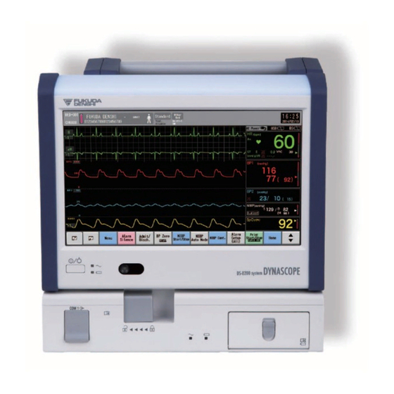
Fukuda Denshi DYNASCOPE 8000 Series Service Manual
Patient monitor
Hide thumbs
Also See for DYNASCOPE 8000 Series:
- Service manual (274 pages) ,
- Operation manual (252 pages) ,
- Maintenance manual (154 pages)

Subscribe to Our Youtube Channel
Related Manuals for Fukuda Denshi DYNASCOPE 8000 Series


Summary of Contents for Fukuda Denshi DYNASCOPE 8000 Series
- Page 1 Series Service Manual Patient Monitor * Before setting up/maintenance, please read this “Service Manual” thoroughly. * After reading, keep this manual for future reference.
- Page 2 • The company and product names used in this manual are trademarks or registered trademarks. • If this manual has pages missing or out of order, contact Fukuda Denshi for replacement. • Only physician or persons instructed by physicians are allowed to use the equipment.
- Page 3 Revision History Model Name Service Manual DS-8200 System Edition Revised Items Reason of the Revision Revised Date New Edition 2014.02 -...
- Page 4 Blank Page...
-
Page 5: Table Of Contents
Preface Thank you for purchasing our product. Before using this product, read the following precautions to make sure the product is used correctly and safely. Safety ··············································································· ii About the Safety Precautions ······································· ii The Meaning of Each Safety Precaution················· ii Warning Labels Attached to the Unit·······················... -
Page 6: Safety
Safety About the Safety Precautions The Meaning of Each Safety Precaution Read this manual thoroughly before use to ensure correct and safe use of the product. Be sure to follow the precautions indicated below, as these are important messages related to safety. -
Page 7: Measurement Unit For Each Parameter
Measurement Unit for Each Parameter The measurement units for this equipment are as follows. Details Parameter Display Unit Default Heart Rate / Pulse (beats per minute) Rate PR_IBP PR_SpO ST Level mm, mv beat/minute PACE beat/minute Impedance RR_IMP (breaths per minute) Respiration Rate Ventilator RR_VENT... - Page 8 Details Parameter Display Unit Default Expiratory E-RES O/L/Sec Resistance Airway Resistance Inspiratory I-RES O/L/Sec Resistance Mean Airway MEAN Pressure Peak Airway PEAK Airway Pressure Pressure Pause Airway PAUSE Pressure Plateau Pressure PLATEAU Peak End Expiratory Peak End Expiratory PEEP Pressure Pressure Inspired Oxygen Inspired Oxygen...
- Page 9 Details Parameter Display Unit Default End-Diastolic Volume EDVI mL/m Index End-Diastolic Volume Vigilance Data EDVI_STAT mL/m Index (STAT Mode) Vigilance Vigilance CEDV End-Systolic Volume Vigilance II End-Systolic Volume ESVI mL/m Vigileo Index Stroke Volume Variance Bispectral Index (no unit) Signal Quality Index Electromyograph Suppression Ratio BIS Data...
-
Page 10: Graphic Symbols
Graphic Symbols Refer to the following for the meaning of the symbol indicated on the equipment. DS-8200 System Main Unit Symbol Description Follow operating instructions (Warning); indicated in blue. Failure to follow operating instructions could place the patient or operator at risk. -
Page 11: Equipment
Symbol Description Waterproof Standard Indicates this equipment complies with IPX1. (Combination of LC-8210, HSB-80, HS-8000 and BS-8210: IPX1, Other situation: IPX0) Year of Manufacture WEEE (Waste Electrical and Electronics Equipment) Indicates a separate collection for electrical and electronic equipment. Indicates that this device bears the CE label in accordance with the provisions of Medical Device Directive 93/42/EEC. - Page 12 Symbol Description This icon (1/3 yellow) indicates that the battery is low and needs to be charged. This icon (1/3 red) indicates that the battery is very low and flashes to alert the low battery status. Immediate battery charge is required. Technical alarm will generate.
-
Page 13: Precautions About The Maintenance
Precaution when Equipment Failure Occurs If the equipment is damaged and in need of repair, user should not attempt service. Label the unit "OUT OF ORDER" and contact Fukuda Denshi. Precaution about Disassembling/Remodeling the Equipment Do not disassemble or remodel the equipment. -
Page 14: Precautions About The Network System
When interference or breakdown occurs in telemetry communication, the user is required to inform the zone manager and the overall manager of the problems. The Zone Manager and Overall Manager are to deal with the problem properly and/or contact their nearest Fukuda Denshi representative for service. -
Page 15: Bidirectional Wireless Communications Module
TCON and to inform the Overall Manager of the problem. The Overall Manager is to deal with the problem properly and/or contact the nearest Fukuda Denshi representative for service. Precautions for Operation The Bidirectional Wireless Communications Module (TCON) uses radio waves to transmit data. - Page 16 When the patient's data may become mixed with a different patient's data due to interference. When there are multiple TCON communication devices set to the same TCON ID and channel (group). When symptoms such as being unable to communicate, unstable communication, or poor reception may occur.
-
Page 17: Precautions When Using With Other Equipment
For more details, contact FUKUDA DENSHI personnel, your institution's professionals, or your pacemaker distributors. Rate meters may continue to count the pacemaker rate during occurrences of cardiac arrest or some arrhythmias. -
Page 18: Electrosurgical Instrument
Electrosurgical Instrument The monitoring system contains protection against interference generated by electrosurgical instruments. However, operating conditions, surgery site with respect to the location of ECG electrodes, or the type of instrument used, may cause noise on the ECG. The noise is generated at the tip of the electrical knife and is difficult to completely eliminate because of the frequency components of the ECG. -
Page 19: Devices
Fukuda Denshi. It is the user's responsibility to contact Fukuda Denshi to determine the compatibility and warranty status of any connection made to another manufacturer's equipment. -
Page 20: Precautions For Using The Equipment
Precautions for Using the Equipment This System When connecting to other equipments, contact Fukuda Denshi. D A N G E R Danger such as electric shock may result to the patient and operator. Warnings about the System Do not connect any damaged / unspecified equipment or cable to any I/O connector. - Page 21 Use only the specified airway adapter manufactured by Respironics Novametrix, LLC. Refer to the section on "Optional Accessories" for list of specified airway adapters. These accessories may be purchased from Fukuda Denshi or any authorized Respironics Novametrix, LLC distributor. W A R N I N G Always consider the circumference of the intubation tube when using the airway adapter.
- Page 22 The display unit utilizes LED for the backlight. Since this LED deteriorates by the life cycle, the display may become dark, scintillate, or may not light by the long term use. In such case, contact Fukuda Denshi. This equipment is intended to be used for only one patient.
- Page 23 Moreover, waveforms may differ somewhat also in a supine position and a standing position (sitting position). Fukuda Denshi recommends to carry out the recording of the ECG by taking into consideration the waveform differences according to electrode positions or postures.
- Page 24 The threshold values for classification of 12-lead ECG interpretation and Minnesota code are set by age and sex as follows: 1. Male and Female of ages 19 years old and above 2. Male of age 12 through 18 years old 3.
- Page 25 Precautions for Single-Patient-Use Type Sensors The sensor can be reused on the same patient as long as the adhesive tape attaches without slippage. But do not reuse on other patients to avoid cross contamination. It is intended for single patient use only. For additional warnings, cautions, or contraindications when using sensors with Nellcor Unit (HS-8312N)/Masimo Unit (HS-8312M), refer to SpO sensor instruction manual.
- Page 26 Precautions about the CO Monitoring (HCP-800/HCP-810) Conduct CO calibration for the following case. If the CO gas calibration is not performed at a specified interval, CO measurement accuracy may be affected and also subsequent gas calibration may not be possible. When 12 months has elapsed from first use, or the accumulated measurement time exceeds 1200 hours.
- Page 27 Precautions about the System Setup When the waveform and numeric data display for each parameter is set to OFF, the alarm and trend input will be also suspended. If the HR/PR source is set to [BP], and if BP waveform/numeric data is set to [Disp.
-
Page 28: Wired Network (Ds-Lanii/ Ds-Laniii)
Wired Network (DS-LANII/ DS-LANIII) Do not connect unspecified device to the wired network. W A R N I N G Do not mix devices with DS-LANII and DS-LANIII setting in the same wired network. The network may cease and proper monitoring may not be possible. When using the wired network transmission, configure the display so that the numeric data corresponded to the waveform is displayed. -
Page 29: Wireless Network System
OFF, this clock is backed up by a lithium primary battery. If incorrect time is displayed when turning ON the power, a low battery may be the cause. In such case, contact Fukuda Denshi for replacing the battery. C A U T I O N... -
Page 30: Precautions About The Ventilator Monitoring
If there are any questions regarding the sensor/relay cable use for SpO measurements of this equipment, please contact Fukuda Denshi. Precautions about the NIBP Cuff Some of the NIBP cuffs used for this equipment contain natural rubber latex which may cause allergic reactions. -
Page 31: Precautions About Transportation
Precautions about Transportation When transporting this equipment, pack it with specified packing materials. C A U T I O N Also, transport it under appropriate environment condition. Monitoring after Power Failure When the power failure is within 30 seconds, monitoring will resume with the display mode and patient information unchanged. -
Page 32: Electromagnetic Compatibility
Electromagnetic Compatibility The performance of this device under electromagnetic environment complies with EN 60601-1-2 (2012) (for Europe) / IEC 60601-1-2: 2007 (for USA). Precautions for Safe Operation under Electromagnetic Influence If any sorts of electromagnetic wave, magnetic field, or static electricity exist around the device, noise interference or malfunction of the device may occur. - Page 33 Compliance to the Electromagnetic Emissions The DS-8200 System is intended for use in the electromagnetic environment specified below. It should be assured that the device is used in such an environment. When measuring only the vital parameters without connection to peripheral equipments (including HLX-801 and Display Unit Extension Cable) Guidance and Manufacturer's Declaration - Electromagnetic Emissions Emissions Test...
- Page 34 Compliance to the Electromagnetic Immunity (1) The DS-8200 System is intended for use in the electromagnetic environment specified below. The customer or the user of the DS-8200 System should assure that it is used in such an environment. Guidance and Manufacturer's Declaration - Electromagnetic Immunity EN 60601-1-2 (for Europe) Electromagnetic Environment Immunity Test...
- Page 35 Compliance to the Electromagnetic Immunity (2) The DS-8200 System is intended for use in the electromagnetic environment specified below. The customer or the user of the DS-8200 System should assure that it is used in such an environment. Guidance and Manufacturer's Declaration - Electromagnetic Immunity EN 60601-1-2 (for Europe) Compliance...
- Page 36 Recommended Separation Distances between Portable and Mobile RF Communications Equipment and the DS-8200 System The customer or the user of the DS-8200 System can help prevent electromagnetic interference by maintaining a minimum distance between portable and mobile RF communications equipment (transmitters) and the DS-8200 System as recommended below, according to the maximum output power of the communications equipment.
- Page 37 Contents Preface This chapter describes the general description of the Chapter 1 General Description equipment. This chapter describes the specification and Chapter 2 Specification performance of the equipment. Chapter 3 This chapter describes the names of parts and their functions of the equipment. Parts Names and Functions Chapter 4 Operational Description This chapter describes the outline of the equipment.
- Page 38 Preface Chapter 3 Part Names and Functions Safety·············································································· ii About the Safety Precautions ···································· ii Name of Parts and Their Functions······························3-2 The Meaning of Each Safety Precaution·············· ii Display Unit: LC-8210·············································3-2 Warning Labels Attached to the Unit···················· ii [Front Side] ·······················································3-2 Measurement Unit for Each Parameter ····················...
- Page 39 LC I/F Board (PCB-7505) ···································· 4-25 Chapter 8 Software Upgrade BATTERY I/F Board (PCB-7487) ························ 4-29 LC Connector (QR/P15-40P(50): HRS)··············· 4-29 Software Upgrade ························································8-2 M-LAN Connector (DRA-20SC-F0R: JAE) ·········· 4-29 Software Version··························································8-3 BS-8210 Base Unit···················································· 4-30 BASE-CPU Board (PCB-7506) Circuit Description·············································· 4-30 Chapter 9 Troubleshooting HSB I/F Board (PCB-7507) ·································...
- Page 40 Cleaning the Touch Panel and Housing ·················· 10-23 Cleaning the Touch Panel ································· 10-23 Cleaning the Housing ········································ 10-24 Cleaning the ECG Lead Cable, Relay Cable ····· 10-24 Disinfecting the Blood Pressure Transducers···· 10-24 Cleaning and Disinfecting the Temperature Probe···································· 10-24 Cleaning the Cardiac Output Relay Cable ·········...
- Page 41 Chapter 1 General Description This chapter describes the general description of the equipment. Composition of the System········································· 1-2 Features ··································································· 1-3...
- Page 42 Composition of the System The DS-8200 system is composed of Display Unit (LC-8210), HS Adapter (HSB-80), Base Unit (BS-8210), Super Unit (HS-8000 Series), Recorder Unit (HR-800) and Gas Unit. <Configuration Example of the DS-8200 system (LC-8210, HSB-80, BS-8210, HS-8000)> [Lineup of Super Unit] Concentration Fixed Parameters Multiparameter...
- Page 43 Features The display unit can display maximum of 14 waveforms. Also, various displays such as enlarged numeric data, trend, or ventilator can be selected according to monitoring conditions. The operation can be performed with the touch panel. Also, frequently used keys can be assigned on the screen as user keys.
- Page 44 Blank Page...
- Page 45 Chapter 2 Specification This chapter describes the specification and performance of the equipment. Specification·······························································2-2 Display Unit: LC-8210·············································2-2 HS Adapter: HSB-80 ··············································2-3 Base Unit: BS-8210 ················································2-4 Super Unit: HS-8000 series····································2-5 Recorder Unit: HR-800 ···········································2-6 Gas Unit I/F: HPD-800/HPD-810 and Gas Unit: HCP-800/HCP-810························2-7 Performance ·······························································2-8...
-
Page 46: Safety
Specification This section states the specification of this equipment. Display Unit: LC-8210 Size 270(W)×66(D)×210(H)mm (not including the protrusion) Weight 1.8kg (not including the accessory) Environmental Conditions Operating Temperature : 10 to 40°C Operating Humidity : 30 to 85 % (non-condensing) Transport / Storage : -10 to 60°C Temperature... -
Page 47: Hs Adapter: Hsb-80
HS Adapter: HSB-80 Size 230(W)×135(D)×210(H)mm (not including the protrusion) Weight 1.5kg (not including the accessory) Environmental Conditions Operating Temperature : 10 to 40°C Operating Humidity : 30 to 85 % (non-condensing) Transport / Storage : -10 to 60°C Temperature Transport / Storage : 10 to 95% (40°C) (non-condensing) Humidity However, for the CF-820 IR Remote Control Unit, the following... -
Page 48: Base Unit: Bs-8210
Base Unit: BS-8210 Size 270(W)×180(D)×92(H)mm (not including the protrusion) Weight 2.5kg (not including the accessory) Environmental Conditions Operating Temperature : 10 to 40°C Operating Humidity : 30 to 85 % (non-condensing) Transport / Storage : -10 to 60°C Temperature Transport / Storage : 10 to 95% (40°C) (non-condensing) Humidity However, for the CF-820 IR Remote Control Unit, the following... -
Page 49: Super Unit: Hs-8000 Series
Super Unit: HS-8000 series Size HS-8312N/8312M : 85 (W) x200 (D) x100 (H) mm (not including the protrusion) Weight HS-8312N/8312M : 1.2kg (not including the accessory) Environmental Conditions Operating Temperature : 10 to 40°C Operating Humidity : 30 to 85 % (non-condensing) Transport / Storage : -10 to 60°C Temperature... - Page 50 Recorder Unit: HR-800 Size HR-800 Recorder Unit : 87 (W) x109 (H) x100 (D) mm (not including the protrusion) Weight HR-800 : 0.54kg (not including the accessory) Environmental Conditions Operating Temperature : 10 to 40°C Operating Humidity : 30 to 85 % (non-condensing) Transport / Storage : -10 to 60°C Temperature...
-
Page 51: Gas Unit I/F: Hpd-800/Hpd-810 And
Gas Unit I/F: HPD-800/HPD-810 and CO Gas Unit: HCP-800/HCP-810 Size 36(W)x91(H)x87(D) mm (not including the protrusion) Weight HPD-800 : 0.3kg (not including the accessory) HPD-810 : 0.18kg (not including the accessory) HCP-800 : 0.4kg (not including the accessory) HCP-810 : 0.22kg (not including the accessory) Environmental Conditions Operating Temperature : 10 to 40°C... -
Page 52: Performance
Performance This section states the performance of this equipment. Display Device : 10.2 inch color LCD Resolution : 1024×600 pixel, refresh frequency 60Hz Function Control : Touch Screen Method Waveform Trace : Stationary Trace Sweep Speed : ECG / SpO / BP (6.25mm/s, 12.5mm/s, 25mm/s, 50mm/s) RESP/CO (6.25mm/s, 12.5mm/s, 25mm/s) - Page 53 R change from 80bpm to 40bpm: Range 5.8 to 6.5 sec., Average 6.2 sec. Time to ALARM for tachycardia: Ventricular Tachycardia 1mVpp, 206bpm: Range 8.2 to 9.1 sec., Average 8.5 sec. Ventricular Tachycardia 2mVpp, 206bpm: Range 7.5 to 8.8 sec., Average 8.0 sec. Ventricular T achycardia 0.5mVpp, 206bpm: Range 10.8 to 13.0 sec., Average 11.9 sec.
- Page 54 Pulse Oximeter Measurement Update Rate: 1 sec. Nellcor Unit (HS-8312N) Measurement Method : 2 Wavelength Pulse Wave Method Wavelength: Approx. 660nm (red light) Approx. 890nm (infrared light) Output: 15mW or below Measurement Range : 1 to 100% Resolution : 1% Measurement Accuracy : Adult: ±3% when 70 to 100% (DS-100A) Neonate: ±2% when 70 to 100% PR Measurement Range: 20 to 250bpm...
- Page 55 The SpO measurement accuracy is determined based on the values of the root-meansquare (rms) difference between SpO readings of the pulse oximeter determined with a CO-oximeter, by healthy adult equipment and values of SaO volunteers. The pulse oximeter equipment measurements are statistically N O T E distributed;...
- Page 56 N O T E monitor. For detailed information of the delay time, refer to Fukuda Denshi. The QRS synchronized signal is not intended to be used as synchronized signal for defibrillator.
- Page 57 Chapter 3 Part Names and Functions This chapter describes the names of parts and their functions of the equipment. Name of Parts and Their Functions···························· 3-2 Display Unit: LC-8210··············································· 3-2 [Front Side] ························································· 3-2 [Rear Side]·························································· 3-3 [Right Side] ························································· 3-3 [Left Side]····························································...
-
Page 58: Name Of Parts And Their Functions
Name of Parts and Their Functions Do not connect a unit or cable not authorized by Fukuda Denshi to any I/O connector. If done so by mistake, the equipment cannot deliver its maximum W A R N I N G performance and the connected units may be damaged, resulting in a safety hazard. -
Page 59: [Rear Side]
[Rear Side] Display Unit Release Lever Used for releasing the unit from the HS Adapter (HSB-80). Speaker Generates alarm sound, HR synchronized sound, etc. Maintenance Cover Used for replacing the short-term backup battery. [Right Side] HLX Storage Cover Stores the telemetry transmitter module (HLX-801). -
Page 60: [Left Side]
[Left Side] Display Unit Extension Cable Connector Connects the HS Adapter with the display unit extension cable. To use the display unit extension cable, the VESA Attachment for LC-8210 (OAO-71A) is required. For details on how to attach the OAO-71A, refer to the OAO-71A Assembly Instruction. -
Page 61: Hs Adapter: Hsb-80
HS Adapter: HSB-80 [Front Side] Display Unit Connector Connects the Display Unit (LC-8210). Display Unit Extension Cable Connector Connects the Display Unit (LC-8210) with the display unit extension cable. To use the display unit extension cable, the VESA Attachment for LC-8210 (OAO-71A) is required. -
Page 62: [Right Side]
[Right Side] Module-LAN Connector Used when connecting to other systems. [Left Side] Super Unit Connector Connects the Super Unit (HS-8000). Release Lever Used for releasing the Super Unit (HS-8000). Battery Cover Used when replacing the battery pack with the cover open. -
Page 63: Base Unit: Bs-8210
Base Unit: BS-8210 [Front Side] HSB Release Lever Serial Connector (COM1) Used to remove the HS Connects the specified Adapter (HSB-80). equipment. Battery Cover Power Supply Indicator Used when replacing the battery Indicates the power supply status. pack with the cover open. Lights when the AC power is Battery Charging LED supplied to the main unit and links... -
Page 64: [Left Side]
[Left Side] U-LINK Connector Connects the Recorder Unit (HR-800). [Top] HS Adapter Connector Connects the HS Adapter (HSB-80). -
Page 65: Super Unit: Hs-8000
Super Unit: HS-8000 Alarm Silence Key [Front Side] BP Zero Balance Indicator Silences the Alarm. The Performs BP zero balance. The Power Supply LED indicator lights during the alarm indicator lights during the BP zero Indicates the power silence condition. balancing. -
Page 66: Recorder Unit
Recorder Unit: HR-800 [Front Side] Printing Indicator Power Supply Indicator Lights during printing. Indicates the power ON/OFF status. Record Key Starts/stops the printing. Open/Close Lever Opens the paper holder by pressing it. Paper Feed Indicator Lights during paper feeding. Paper Feed Key Feeds the paper. -
Page 67: Gas Unit: Hcp-800
Gas Unit: HCP-800 [Front Side] Power Supply Indicator Indicates the power ON/OFF status. It will light in green while the power is ON. Sampling Tube Connector Connects the sampling tube manufactured by Covidien. Clip Attaches to the bedside rail or headboard for bedside use. -
Page 68: Gas Unit: Hcp-810
Gas Unit: HCP-810 [Front Side] Clip Attaches to the bedside rail or headboard for bedside use. (supplied as accessory) Power Supply Indicator Indicates the power ON/OFF status. It will light in green while the power is ON. Sampling Tube Connector Connects the sampling tube manufactured by Covidien. -
Page 69: Gas Unit I/F: Hpd-800
Gas Unit I/F: HPD-800 [Front Side] Power Supply Indicator Indicates the power ON/OFF status. It will light in green while the power is ON. Connector Connects to the Capnostat 5 manufactured by Respironics. Clip Attaches to the bedside rail or headboard for bedside use. -
Page 70: Gas Unit I/F: Hpd-810
Gas Unit I/F: HPD-810 [Front Side] Clip Attaches to the bedside rail or headboard for bedside use. Power Supply Indicator Indicates the power ON/OFF status. It will light in green while the power is ON. Connector Connects to the Capnostat 5 manufactured by Respironics. -
Page 71: External Appearance
External Appearance [DS-8200 system] (LC-8210 Display Unit, HSB-80 HS Adapter, BS-8210 Base Unit) 270(W) x 201(D) x 302(H) mm (not including the protrusion) Weight: 7.0kg 3-15... - Page 72 [Super Unit HS-8000] 85(W) x 200(D) x 100(H) mm (not including the protrusion) Weight: 1.2kg [Recorder Unit HR-800] 87(W) x 100(D) x 108.5(H) mm (not including the protrusion) Weight: 0.54kg 3-16...
- Page 73 Chapter 4 Operational Description This chapter describes the outline of the equipment. LC-8210 Display Unit ·················································4-2 Main CPU Board (PCB-7500) Circuit Description···4-2 ALARM INDICATOR Board (PCB-7501) ················4-9 HSB I/F Board (PCB-7502) ····································4-9 STANDBY KEY Board (PCB-7485) ······················4-13 LCD Touch Panel (LCD UNIT SAS DS-8100) ······4-13 HSB Connector (QR/P15-40S(50): HRS) ·············4-13 Lithium Battery (BR3032・1VC: PANASONIC) ·····4-13 Ni-MH Battery (250H073676: VARTA) ·················4-13...
-
Page 74: Lc-8210 Display Unit
LC-8210 Display Unit This section explains the block diagram and the functions of the LC-8210 Display Unit. Main CPU Board (PCB-7500) Circuit Description The Main CPU Board controls, displays, and records the monitor. The input signal operations of the touch panel, etc are processed by the CPU and then the display of the monitor or each measurement condition will change. - Page 75 SDRAM SDRAM holds various data. It conducts backup operation for approximately 5 minutes, and backs up the recall and trend data. Also, the program stored in the flash memory is loaded in the SDRAM and executed after starting. SRAM SRAM stores memory for Monitor Setup. Using the lithium battery, backup is available for approximately 6 years.
- Page 76 DS-LAN This is the LAN interface to communicate with other monitor units using special protocol, and is controlled by a special controller. Module-LAN This is the interface to communicate with the HS-8000 Super Unit and other systems using special protocol, and is controlled by a special controller. Secondary battery/Charge control The nickel hydride rechargeable battery is used as a short-term backup battery.
- Page 77 HSB IF connector board connector (CN6) Signal Name Description Signal Level V1_LVDS_Y3P LVDS output V1_LVDS_Y0P LVDS output V1_LVDS_Y3M LVDS output V1_LVDS_Y0M LVDS output LCD_DETCT LC-8210 detection V1_LVDS_Y1M LVDS output V1_LVDS_Y1P LVDS output V1_LVDS_CLKOUTP LVDS output V1_LVDS_CLKOUTM LVDS output DS_TX_LANP LAN output DS_TX_LANM LAN output V1_LVDS_Y2P...
- Page 78 LCD connector (CN7) Signal Name Description Signal Level +3.3V_P LCD module power supply 3.3V TxOut0- Pixel data - LVDS +3.3V_P LCD module power supply 3.3V TxOut0+ Pixel data + LVDS TxOut1- Pixel data - LVDS TxOut1+ Pixel data + LVDS TxOut2- Pixel data - LVDS...
- Page 79 Jig connector (CN11) Signal Name Description Signal Level - - - - * Due to factory adjustment, no description. Touch panel connector (CN12) Signal Name Description Signal Level Right drive XR_REF Right reference XL_REF Left reference Left drive YU_REF Top reference YL_REF Bottom reference Bottom drive...
- Page 80 ●External Connector CF-CARD Connector (CN16) Signal Signal Description Description Name Name Signal GND /CD1 Card Detect 1 Card Data D3 Card Data D11 Card Data D4 Card Data D12 Card Data D5 Card Data D13 Card Data D6 Card Data D14 Card Data D7 Card Data D15 Chip Enable 1...
-
Page 81: Alarm Indicator Board (Pcb-7501)
SD-CARD Connector (CN17) Signal Name Description Signal Level DAT3/CS Data signal 3 CMD/DI Command signal Power supply CLK/SCLK Clock DAT0/DO Data signal 0 DAT1 Data signal 1 DAT2 Data signal 2 CARD DETECT Card detection signal Write-protect detection signal COMMON Common signal (GND) SHIELD Shield... - Page 82 ●Internal Connector CPU board connector (CN1) Signal Name Description Signal Level V1_LVDS_Y3P LVDS output V1_LVDS_Y0P LVDS output V1_LVDS_Y3M LVDS output V1_LVDS_Y0M LVDS output LCD_DETCT LC-8210 detection V1_LVDS_Y1M LVDS output V1_LVDS_Y1P LVDS output V1_LVDS_CLKOUTP LVDS output V1_LVDS_CLKOUTM LVDS output DS_TX_LANP LAN output DS_TX_LANM LAN output V1_LVDS_Y2P...
- Page 83 HSB connector 1 (CN3) Signal Name Description Signal Level DS_RX_LANP LAN input DS_TX_LANP LAN output DS_RX_LANM LAN input DS_TX_LANM LAN output CHARGE board control signal +18V_EN output LCD_DETCT LC-8210 detection M_RX_LANP LAN input M_TX_LANP LAN output M_RX_LANM LAN input M_TX_LANM LAN output LVDS1P LVDS output...
- Page 84 ●External Connector HSB connector (CN2) Signal Name Description Signal Level +18V 18V power supply input +18V 18V power supply input M_TX_LANP LAN output M_TX_LANM LAN output M_RX_LANP LAN input M_RX_LANM LAN input DS_TX_LANP LAN output DS_TX_LANM LAN output DS_RX_LANP LAN input DS_RX_LANM LAN input LVDS0P...
-
Page 85: Standby Key Board (Pcb-7485)
STANDBY KEY Board (PCB-7485) STANDBY KEY Board judges the standby key operation, receives remote control signal light and measures ambient light brightness, and transmits them to the Main CPU board and the HSB-80 HS Adapter POWER board. ●Internal Connector Main CPU board connector (CN1) Signal Signal Description... -
Page 86: Hsb-80 Hs Adapter
HSB-80 HS Adapter This section explains the block diagram and the functions of the HSB-80 HS Adapter. POWER Board (PCB-7499) Circuit Description POWER Board selects the power supply to be used from the BS-8210 Base Unit, other system connected by the module LAN or the BTO-008 Lithium-ion Battery Pack. It also charges the BTO-008 Lithium-ion Battery Pack, remotely controls the start-up and monitors the voltage. - Page 87 ●Internal Connector Battery board connector (CN1) Signal Signal Description Description Name Name Battery Li-ion battery +BAT_V IIC_DATA communication + terminal data Li-ion battery +BAT_V SGND Signal GND + terminal Li-ion battery BAT_DETE +BAT_V Battery detection + terminal Battery thermistor Li-ion battery THM+ -BAT_V terminal...
- Page 88 SIGNAL board connector (CN4) Signal Name Description Signal Level RESERVE Reserve AC power supply connection status BS_GOOD input +18V_MLAN Module-LAN 18V power supply +18V_MLAN Module-LAN 18V power supply +18V_MLAN Module-LAN 18V power supply +18V_MLAN Module-LAN 18V power supply +18V_MLAN Module-LAN 18V power supply +18V_MLAN Module-LAN 18V power supply +18V_MLAN...
- Page 89 HS IF board connector (CN6) Signal Name Description Signal Level /HS_RST Super unit reset signal Super unit power supply control HS_PWR_EN signal +12V 12V power supply +12V 12V power supply +12V 12V power supply +12V 12V power supply LC IF board connector (CN7) Signal Name Description Signal Level...
-
Page 90: Signal Board (Pcb-7503) Circuit Description
SIGNAL Board (PCB-7503) Circuit Description SIGNAL Board receives Module-LAN signal from Display Unit (LC-8210), Super Unit (HS-8000) or other system, and controls the communication routes. LC I/F Board Module LAN (Other system) PCB-7505 Module-LAN Connector LAN SW HS-8000 Super Unit POWER Board DC/DC PCB-7499... - Page 91 ●Internal Connector M-LAN connector power supply cable connector (CN2) Signal Name Description /DETECT1 GND connection /DETECT2 GND connection /MLAN_RST HS-8000 reset signal MLAN_PWREN HS-8000 power supply enable signal RESERVE RESERVE RESERVE RESERVE 18VIN Module LAN power supply 18VIN Module LAN power supply M-LAN connector signal cable connector (CN8) Signal Name Description...
- Page 92 LC I/F board connector (CN6) Signal Name Description Signal Level LC_RX_LAN+ Module LAN output LC_TX_LAN+ Module LAN input LC_RX_LAN- Module LAN output LC_TX_LAN- Module LAN input DS_RX_LAN+ DS-LAN output DS_TX_LAN+ DS-LAN input DS_RX_LAN- DS-LAN output DS_TX_LAN- DS-LAN input LVDS1P LVDS input LVDS0P LVDS input LVDS1M...
- Page 93 POWER board connector (CN5) Signal Name Description Signal Level RESERVE Reserve AC power supply connection status BS_GOOD output +18V_MLAN Module-LAN 18V power supply +18V_MLAN Module-LAN 18V power supply +18V_MLAN Module-LAN 18V power supply +18V_MLAN Module-LAN 18V power supply +18V_MLAN Module-LAN 18V power supply +18V_MLAN Module-LAN 18V power supply +18V_MLAN...
- Page 94 ●External Connector BS connector (CN4) Signal Name Description Signal Level +18V_BS 18V power supply input HSB-80 connection detection Negative logic /HSB_DETECT_A 3.3V signal 1/2 LVDS0+ LVDS output LVDS0- LVDS output LVDS2+ LVDS output LVDS2- LVDS output DS-LAN_TXP DS-LAN output DS-LAN_TXM DS-LAN output HSB-80 charge detection Positive logic...
-
Page 95: Hs I/F Board (Pcb-7504)
HS I/F Board (PCB-7504) The connector for the HS-8000 is mounted. It relays power supply and communication between the POWER board, the SIGNAL board and the HS-8000. ●Internal Connector POWER board connector (CN1) Signal Name Description /HS_RST HS-8000 reset signal HS_PWER_EN HS-8000 power supply enable signal +12V... - Page 96 ●External Connector HS connector (CN3) 12 11 10 15 14 13 Signal Name Description Module LAN signal : HSB-800 → HS-8000 (-) Module LAN signal : HSB-80 → HS-8000 (+) HS_PWER_EN HS-8000 power supply enable signal Module LAN signal : HSB-80 ← HS-8000 (-) /HS_RST HS-8000 reset signal Module LAN signal : HSB-80 ←...
- Page 97 LC I/F Board (PCB-7505) The connector which connects the HSB-80 HS Adapter and the LC-8210 Display Unit is mounted. It relays communication between the CHARGE board, the SIGNAL board and the LC-8210. ●Internal Connector LC connector (CN5) Signal Name Description Signal Level DS_RX_LANP LAN output...
- Page 98 LC connector 2 (CN4) Signal Name Description Signal Level BS_TX BS serial input RS-232C REC_TX Recorder serial input RS-232C BS_RX BS serial output RS-232C REC_RX Recorder serial output RS-232C HSB_TX HSB serial output RS-232C CHG_LED LED control signal HSB_RX HSB serial input RS-232C FULL_LED LED control signal...
- Page 99 SIGNAL board connector (CN2) Signal Name Description Signal Level M_RX_LANP Module LAN input M_TX_LANP Module LAN output M_RX_LANM Module LAN input M_TX_LANM Module LAN output DS_RX_LANP DS-LAN input DS_TX_LANP DS-LAN output DS_RX_LANM DS-LAN input DS_TX_LANM DS-LAN output LVDS1P LVDS output LVDS0P LVDS output LVDS1M...
- Page 100 ●External Connector HSB connector (CN1) Signal Name Description Signal Level +18V 18V power supply input +18V 18V power supply input M_TX_LANP LAN output M_TX_LANM LAN output M_RX_LANP LAN input M_RX_LANM LAN input DS_TX_LANP LAN output DS_TX_LANM LAN output DS_RX_LANP LAN input DS_RX_LANM LAN input LVDS0P...
- Page 101 BATTERY I/F Board (PCB-7487) BATTERY I/F Board connects the BTO-008 Lithium-ion Battery Pack and the POWER Board. ●Internal Connector Battery connector (CN1) Signal Signal Description Description Name Name Battery Li-ion battery +BAT IIC_DATA communication + terminal data Li-ion battery +BAT SGND Signal GND + terminal...
- Page 102 BS-8210 Base Unit This section explains the block diagram and the functions of the BS-8210 Base Unit. BASE-CPU Board (PCB-7506) Circuit Description BASE-CPU Board selects the power supply to be used from the AC power supply unit or the battery. It also charges the specified battery (BTO-008), communicates with external devices, monitors the voltage, and controls the fan during battery charging.
- Page 103 DS-LAN This is the LAN interface connector to communicate with other monitor units using special protocol. The I/O signal line of this interface is insulated. Serial Interface (COM1 / COM2 / Status II-1 / Status II-2) Serial interface is provided with the power circuit to supply insulation power and RS-232C interface circuit.
- Page 104 FAN connector (CN26) Signal Description Name FAN power supply + RED output 6V FAN rotation 3 YELLOW detection - BLACK Debug connector (CN7) Signal Signal Description Description Name Name Power supply output Power supply output I/O TCK /TRST /TRST /RES /RES EMLE EMLE...
- Page 105 SIGNAL CABLE connector (CN3) Signal Name Description Signal Level HSB-80 connection detection /HSB_DETECT_A Negative logic 3.3V signal 1/2 LVDS0P LVDS input LVDS1P LVDS input LVDS0M LVDS input LVDS1M LVDS input LVDS2P LVDS input LVDS3P LVDS input LVDS2M LVDS input LVDS3M LVDS input LVDS_CLKP LVDS input...
- Page 106 ●External Connector DS-LAN II connector (CN5) Signal Name Description Signal Level 10BASE-T / Transmit data + 100BASE-TX 10BASE-T / Transmit data - 100BASE-TX 10BASE-T / Receive data + 100BASE-TX Not connected - Not connected - 10BASE-T / Receive data - 100BASE-TX RESERVED Reserved...
- Page 107 UNIT-LINK connector (CN7) Signal Name Description Signal Level TX1+ Transmit data 1+ RS-485 RX1+ Receive data 1+ RS-485 TX2+ Not connected RX2+ Not connected +18V power supply +18V power supply +18V power supply Digital GND Digital GND TX1- Transmit data 1- RS-485 RX1- Receive data 1-...
- Page 108 Status II connector (Status input/output signal) (CN9, 10) Pin3 Pin1 Pin7 Pin5 Pin4 Pin8 Pin2 Pin9 Pin6 Signal Name Description Signal Level Open collector output ALM_OUT1 Alarm output 1 (Pull-up resistor) Alarm output 2 + Photo MOS relay ALM_OUT2+ (Isolation) contact Serial transmit data output RS232C...
- Page 109 HSB I/F Board (PCB-7507) The connector which connects the BS-8210 Base Unit and the HSB-80 HS Adapter is mounted. It relays communication between the BASE-CPU Board and the HSB-80. ●Internal Connector POWER CABLE connector (CN1) Signal Name Description Signal Level 1 to 10 +18V 18V power supply...
- Page 110 ●External Connector HSB connector (CN3) Signal Name Description Signal Level +18V_BS 18V power supply output HSB-80 connection detection signal Negative logic /HSB_DETECT_A 3.3V LVDS0+ LVDS input LVDS0- LVDS input LVDS2+ LVDS input LVDS2- LVDS input DS-LAN_TXP DS-LAN input DS-LAN_TXM DS-LAN input HSB-80 charge detection input Positive logic BAT_CHG...
- Page 111 BATTERY I/F Board (PCB-7487) BATTERY I/F Board connects the BTO-008 Lithium-ion Battery Pack and the BASE-CPU Board with the BATTERY cable. (Common with DS-8100, HSB-80) ●Internal Connector Battery connector (CN1) Signal Signal Description Description Name Name Battery Li-ion battery +BAT IIC_DATA communication + terminal...
- Page 112 Blank Page 4-40...
- Page 113 Chapter 5 Wiring Diagram This chapter describes the wiring diagram of the equipment. DS-8200 System ·························································5-2...
- Page 114 DS-8200 System This section shows the block diagram of the DS-8200 system. Alarm Indicator(Alarm LED Board PCB-7501) Transmitter Unit LC-8210 (HLX-801) Battery for Long Battery for Short ② term backup term backup Telemeter CN ⑨ ⑥ Main CPU Board PCB-7500 ③...
- Page 115 CAUTION To repair a connector or cable, replace the entire board or contact Fukuda Denshi for service. Parts may be damaged when repairing/detaching connectors on the board as they are very small and pin-pitch is very narrow. List of connection cables for LC-8210...
- Page 116 Blank Page...
- Page 117 Chapter 6 Spare Parts List This chapter describes the spare parts of the equipment. LC-8210 Spare Parts ···················································6-2 HSB-80 Spare Parts·····················································6-4 BS-8210 Spare Parts ···················································6-6...
- Page 118 LC-8210 Spare Parts The board assemblies of the LC-8210 are as follows: Item Code Item Item Name Note 9F0104970 STANDBY KEY board 7485 SAS DS-8100 Common with DS-8100 9F0105060 CPU board 7500 SAS DS-8200 9F0105070 LC-8210 ALARM LED board 7501 SAS DS-8200 9F0105080 LC-8210 HSB I/F board 7502 SAS DS-8200...
- Page 119 The assembly mechanism parts of the LC-8210 are as follows: Item Code Item Name Model Type Note 5H0110640 LCD front case U 5H0110520 LCD rear case U 9H0106410 Link arm SU 6C0129780 LCD stopper 6C0129790 LCD lock lever 9H0106420 LCD release lever SU 5H0110650 Stopper cover U 9H0106440...
- Page 120 HSB-80 Spare Parts The board assemblies of the HSB-80 are as follows: Item Code Item Item Name Note 9F0104990 BATTERY I/F board 7487 SAS DS-8100 Common with DS-8100 9F0105050 HSB-80 POWER board 7499 SAS DS-8200 9F0105090 HSB-80 SIGNAL board 7503 SAS DS-8200 9F0105100 HSB-80 HS I/F board 7504 SAS DS-8200...
- Page 121 The assembly mechanism parts of the HSB-80 are as follows: Item Code Item Name Model Type Note 5H011058A Bottom cover U 5H011059A Top cover U 5H0110540 Side cover U 6C0129140 Protector A Front 9H0106290 Protector B Front SU 9H0106300 Protector A Rear SU 5H0110600 Protector B Rear U 6C0129180...
- Page 122 BS-8210 Spare Parts The board assemblies of the BS-8210 are as follows: Item Code Item Item Name Note 9F0104990 BATTERY I/F board 7487 SAS DS-8100 Common with DS-8100 9F0105120 CPU board 7506 SAS DS-8200 9F0105130 HSB I/F board 7507 SAS DS-8200 The spare electrical parts of the BS-8210 are as follows: Item Code Item...
- Page 123 The assembly mechanism parts of the BS-8210 are as follows: Item Code Item Name Model Type Note 5H0110610 Base Bottom U 5H0110620 Base top U 9H0106350 Lock release button SU 6C012939A Battery compartment upper cover 5H0110630 Battery lid SU 6C0129410 Battery lid locking tab 6C0129420 Battery lid knob...
- Page 124 The labels of the BS-8210 are as follows: Item Code Item Name Model Type Note 5H0110260 Care label (Battery) 5H0111940 Power supply label...
- Page 125 Chapter 7 Assembly Diagram This chapter describes the assembly diagram. LC-8210 Assembly (1)·············································· 7-2 LC-8210 Assembly (2)·············································· 7-3 LC-8210 Assembly (3)·············································· 7-4 LC-8210 Assembly (4)·············································· 7-5 LC-8210 Assembly (5)·············································· 7-6 LC-8210 Assembly (6)·············································· 7-7 LC-8210 Assembly (7)·············································· 7-8 LC-8210 Assembly (8)·············································· 7-9 HSB-80 Assembly (1) ·············································...
- Page 126 LC-8210 Assembly (1) ●LCD front case assembly Detailed drawing A Scale 1:1 Match corners of the indicated parts Detailed drawing B Scale 1:1 Attaching order 4 Attaching order 1 Attaching order 2 Attaching order 3 LC-8210 CPU board Double Washer Sems M3x8 (x2) 1M0104720 310-16675 Standby key connecting cable...
- Page 127 LC-8210 Assembly (2) ●Stopper cover assembly HSB I/F board HSB I/F board Double Washer Sems M3x8 (x2) 1Z0026020 CKN clamp CKN-05 1F0104440 Connector QR/P15-40S(50) 1M010479A 310-16682 HSB connector connection cable 2 1M0104780 310-16681 HSB connector connection cable 1 6C0131090 310-16706 Waterproof sheet (Stopper cover) 5H0110650 310-16314...
- Page 128 LC-8210 Assembly (3) ●LCD stopper assembly Double Washer Sems M3x8 (x2) E ring Nominal diameter 2.5 (x2) 6C0079850 Duracon (POM) washer CC-0310-10 6C0129780 310-16311 LCD stopper 6C0129930 310-16332 Link shaft 9H0106410 310-16310 Link arm SU 9H0106420 310-16313 LCD release lever SU Item Code Drawing No.
- Page 129 LC-8210 Assembly (4) ●LCD rear case assembly Double Washer Sems M3x8 (x2) LC-8210 CPU board Label position LC-8210 CPU board LC-8210 CPU board Double Washer Sems M3x8 (x2) Double Washer Sems M3x8 (x5) 6C0133860 310-17098 Cushion (Ferrite core) 5H0110530 310-16707 Waterproof grade label (IPX1) 5H0110280 310-16333...
- Page 130 LC-8210 Assembly (5) ●Card connector cover assembly 6C0129880 310-16325 Lock lever retainer 6C0102460 Ultra spring DC145 6C0129870 310-16324 Cover lock lever 6C0129860 310-16323 Card connector cover Item Code Drawing No. Item/Model Q’ty Note...
- Page 131 LC-8210 Assembly (6) ●Inner frame assembly Double Washer Sems M3x8 (x2) HLX-801 connection cable routing Pan-head screw M2x3 (x4) Double Washer Sems M3x8 (x7) Double Washer Sems M3x8 1Z0100780 Retaining washer for screw TM-147-1 6C0129850 310-16322 Telemeter cover 1M0104770 310-16680 HLX-801 connection cable 1M0104750 310-16678...
- Page 132 LC-8210 Assembly (7) ●Battery holder assembly LC-8210 CPU board 1Z0100060 SK binder SKB-1.5M 6C0077480 310-10316 Ni-MH battery cover Common with DSC-7300 1U001019A 680-4175 Ni-MH battery 250H-073676 6C0127690 310-15798 Battery holder Common with DS-8100 Item Code Drawing No. Item/Model Q’ty Note...
- Page 133 LC-8210 Assembly (8) ●Final assembly Double Washer Sems M3x8 (x4) Double Washer Sems M3x8 (x7) Double Washer Sems M3x8 Double Washer Sems M3x8 5H0108130 310-1548 Caution label (Federal Law) 9E0119840 Rating Label (with a number assigned) 1Z0100780 Retaining washer for screw TM-147-1 5H0110670 310-16326 Maintenance cover SU...
- Page 134 HSB-80 Assembly (1) ●Side cover assembly M3 pan head step screw (x2) (Connector accessories) Lubrication position Lubrication range Cross-section A-A Scale 1:1.5 Note) * Before assembly, lubricate the indicated range. (Possible to lubricate beyond the indicated range) Lubricant: HANARL RX-4339 (Kanto Kasei Ltd.) E ring Nominal diameter 2 (x2) E ring Nominal diameter 2...
- Page 135 HSB-80 Assembly (2) ●Top cover assembly Signal board Double Washer Sems M3x8 (x2) Double Washer Double Washer Sems M3x8 (x3) Sems M3x8 (x3) Double Washer Sems M3x8 (x2) LC I/F board HSB-80 Power board Double Washer Sems M3x8 (x6) 9H0106320 310-16358 Connector holder SU 1Z0026040...
- Page 136 HSB-80 Assembly (3) ●Bottom cover assembly Double Washer Sems M3x8 (x4) Double Washer Sems M3x8 (x4) HSB-80 Power board Double Washer Sems M3x8 1Z0103240 TL Clamp TL-19AN 410-5134 Battery compartment upper cover Common with assembly BS-8210 1M010488A 310-16691 Battery board connection cable 9F0105090 HSB-80 SIGNAL board (PCB-7503 SAS) 6C0131440...
- Page 137 HSB-80 Assembly (4) ●Handle assembly 6C0129310 310-16365 Handle core 6C0129190 310-16352 Handle lower case 6C0129180 310-16351 Handle upper case Item Code Drawing No. Item/Model Q’ty Note 7-13...
- Page 138 HSB-80 Assembly (5) ●Protector A Front assembly P tight (with washer) Nominal diameter 3x8 E ring Nominal diameter 2 (x2) Note) * Pay attention to the mounting direction of the “Battery lid axis”. 6C0113170 Ultra spring C124 6C0129430 310-16380 Battery lock 6C0129440 310-16381 Lock stopper...
- Page 139 HSB-80 Assembly (6) ●HS I/F board assembly Double Washer Sems M3x8 (x2) 6C0113560 310-13768 Floating collar Common with HSA-80 6C0100320 310-11941 Floating spacer Common with MGU-701 9F0105100 HSB-80 HS I/F board (PCB-7504 SAS) 6C0129300 310-16364 Connector holding plate Item Code Drawing No.
- Page 140 HSB-80 Assembly (7) ●Protector A Rear assembly Double Washer Sems M3x8 (x4) 6C0131130 310-16715 Waterproof sheet (LC/IF) 410-5124 HS I/F board assembly 9H0106300 310-16346 Protector A Rear SU Item Code Drawing No. Item/Model Q’ty Note 7-16...
- Page 141 HSB-80 Assembly (8) ●Protector B Rear assembly P tight (with washer) Nominal diameter 3x8 HSB-80 Signal board HSB-80 Signal board Double Washer Sems M3x12 (x2) 1M0104890 310-16693 M-LAN connector signal cable 6C0129260 310-16360 Rear connector cover 5H0110600 310-16348 Protector B Rear U Item Code Drawing No.
- Page 142 HSB-80 Assembly (9) ●Final assembly Double Washer Sems M3x8 (x7) Double Washer Sems M3x8 (x4) Double Washer Sems M3x8 (x2) Double Washer Sems M3x8 (x2) Double Washer Sems M3x8 (x4) Double Washer Sems M3x8 (x7) Production Double Washer mark label Detailed Sems M3x8 (x4) drawing C...
- Page 143 BS-8210 Assembly (1) ●HSB I/F board assembly P tight (with washer) Nominal diameter 3x8 (x2) P tight (with washer) Nominal diameter 3x8 (x2) P tight (with washer) Nominal diameter 3x8 (x4) E ring Nominal diameter 2 (x2) Ties PCB-7507_PE cable and POWER cable together BS-8210 CPU board BS-8210 CPU board 1Z0100060...
- Page 144 BS-8210 Assembly (2) ●Lock release button assembly Double Washer Sems M3x8 (x2) 6C0129720 Ultra spring DC557 9H0106350 310-16373 Lock release button SU 6C0129490 310-16387 Lock release button pedestal 6C0129480 310-16386 Lock release button base Item Code Drawing No. Item/Model Q’ty Note 7-20...
- Page 145 BS-8210 Assembly (3) ●Rotary damper assembly Double Washer Sems M3x8 (x2) 6C0129600 310-16399 Rotary damper mounting plate 1Z0102910 Rotary damper TD62R1-900 Item Code Drawing No. Item/Model Q’ty Note 7-21...
- Page 146 BS-8210 Assembly (4) ●Base top assembly Lightly press ⑫ and tighten the screw. Lubrication position Double Washer Sems M3x8 (x2) Double Washer Sems M3x8 (x5) Installing Rotary damper Cross- Cross- Section Section Lubrication position Cross- Lubrication range Section Double Washer Sems M3x8 Double Washer Sems M3x8 (x4)
- Page 147 BS-8210 Assembly (5) ●Battery cover assembly 5H0110260 310-16408 Care label (Battery) 6C0129640 310-16403 Battery lid spring 6C0129420 310-16379 Battery lid knob 6C0129410 310-16378 Battery lid locking tab 5H0110630 310-16376 Battery lid SU Item Code Drawing No. Item/Model Q’ty Note 7-23...
- Page 148 BS-8210 Assembly (6) ●Battery compartment upper cover assembly Double Washer Sems M2x8 (x2) 6C012939A 310-16375 Battery compartment upper cover 9F0104990 BATTERY I/F board (PCB-7487 SAS) Common with DS-8100 Item Code Drawing No. Item/Model Q’ty Note 7-24...
- Page 149 BS-8210 Assembly (7) ●AC inlet assembly Double Washer Sems M3x8 Flat head screw M3x6 (x2) SW M6 Nut M6 (x2) AC power supply unit 6C0131160 310-16722 Isolation sheet B (Bottom) 6C012967A 310-16406 Isolation sheet (Bottom) 5H0056010 154-3568 Interior earth mark label Common with FX-326U 1M010497A...
- Page 150 BS-8210 Assembly (8) ●Base bottom assembly Double Washer Sems M3x8 (x4) Double Washer Sems M3x8 (x4) Double Washer Sems M3x8 Double Washer Sems M3x8 (x5) Double Washer Sems M3x14 (x2) * After tightening the inch screw, apply “Screw lock” from the underside. Double Washer Sems M3x8 (x8) Double Washer...
- Page 151 5T0035420 Inch screw XM4Z-0023 6C0131150 310-16721 Rear blanking plate 6C0131140 310-16720 Side blanking plate 6C0133860 310-17098 Cushion (Ferrite core) 6C0129660 310-16405 AC connector retainer clip (L type) 6C0129590 310-16448 Fan mounting plate 6C0101700 Locking wire clamp LWC-3AB 6C0129690 310-16449 Thermal sheet (Power) 6C0111560 310-16813 Waterproof sheet B (Base bottom)
- Page 152 BS-8210 Assembly (9) ●Final assembly Double Washer Sems M3x8 Ties AC inlet_PE cable and PCB-7507_PE cable together Double Washer Sems M3x8 (x4) 5H0111940 310-17377 Power supply label (EXP) 9E0119880 Rating Label (with a number assigned) 1Z0100060 SK binder SKB-1.5M 410-5132 Base top assembly 410-5136 Base bottom assembly...
- Page 153 Chapter 8 Software Upgrade This chapter describes the software upgrade of the equipment. Software Upgrade ························································ 8-2 Software Version·························································· 8-3...
- Page 154 →Use a CF card that has been formatted on the DS-8200 or DS-8500. ・Boot block was deleted. →Contact Fukuda Denshi. Remove the CF Card and restart. When the Home Display is displayed, the software upgrade is complete. Then remove the CF card from the monitor and restart the monitor.
- Page 155 Software Version After the software upgrade is complete, check the software version on the main unit. Press the Menu → Maint. → Program Version keys. The software version of the DS-8200 will be displayed. Check if the installed version is correct.
- Page 156 Blank Page...
- Page 157 Chapter 9 Troubleshooting This chapter describes the troubleshooting tips and procedures of the equipment. Backup ···································································9-2 Alarm Sound···························································9-2 Touch Panel ···························································9-3 Wired Network (DS-LAN ΙΙ/ΙΙΙ) ·······························9-3 Telemetry ·······························································9-4 TCON (Only for USA) ·············································9-5 Remote Control Unit ···············································9-5 General···································································9-5 Ventilator ································································9-7 Patient Input ···························································9-8...
-
Page 158: Backup
: The long-term backup battery on the main CPU board is depleted. Solution : Contact Fukuda Denshi or replace the long-term backup battery. (For details, refer to “Chapter 10 Maintenance”.) The display configuration and other setups are initialized every time the power is turned ON. -
Page 159: Touch Panel
Touch Panel The touch panel keys are out of alignment. Cause : The keys may have shifted due to change over time. Solution : Calibration is required. Refer to the section of TOUCH PANEL ADJUSTMENT in “Chapter 10 Maintenance” to perform the calibration. The touch panel does not properly function. -
Page 160: Telemetry
: The connection cable off or a defective cable can be considered. Check the connection between the HLX-801 and LC-8210. Reboot the equipment. When communication cannot be performed, failure of the HLX-801 or connection cable can be considered. Contact Fukuda Denshi. -
Page 161: Tcon (Only For Usa)
TCON (Only for USA) Cannot communicate with the central monitor. The "Chk TCON Reception” message is displayed. Cause 1 : The location is too far from the central monitor. Solution : Readjust the location so as not to be too far from the central monitor. Cause 2 : The setup is not correct. - Page 162 : Immediately turn off the power and stop using the device. Use the unit in an environment where the operating temperature range is between 10 and 40℃. If the message is still displayed, a failure can be considered. Contact Fukuda Denshi. The “DS-8200 Check Rotary SW” message is displayed.
-
Page 163: Ventilator
Ventilator The “Vent. Disable” message is displayed. Cause : One of the following situations is observed. ・Waiting to communicate with ventilator. ・Waiting to communicate with ventilator after the power of the DS-8200 system is turned ON. ・”Vent. Invalid” is displayed for the connection status message and OFF is selected on the ventilator display. -
Page 164: Patient Input
Cause 3 : The communication setup of the DS-8200 system and ventilator does not match. Solution : The communication setup of the DS-8200 system and ventilator is fixed as follows. Check the communication setup of the ventilator. For procedures, refer to the operation manual of the ventilator. Servo-900/300/i/s No network setting. - Page 165 The “HS-8000 SpO Failure” message is displayed. Cause : A communication error with the HS-8000 SpO Unit exists, or error information is received from the SpO Unit. Solution : Parameter cannot be measured properly in this situation. The unit needs to be replaced.
- Page 166 Blank Page 9-10...
- Page 167 Chapter 10 Maintenance This chapter describes the maintenance of the equipment. DIP Switch/Rotary Switch Setup···························· 10-2 Periodic Replacement············································10-26 DIP Switch Setup················································· 10-2 Replacing the NIBP Unit·····································10-27 Rotary Switch Setup ············································ 10-3 Usable Life of NIBP Unit ·······························10-27 Replacing the Short-Term Backup Battery ·········10-27 Test Menu ································································...
-
Page 168: Dip Switch/Rotary Switch Setup
DIP Switch/Rotary Switch Setup This section describes the settings of the DIP switch and rotary switch. DIP Switch Setup The DIP switch is located inside the maintenance cover of the LC-8210. SW No. Default Description (When ON) Not used. (Reserved function) Not used. -
Page 169: Rotary Switch Setup
Rotary Switch Setup The Rotary switch is located inside the maintenance cover of the LC-8210. SW No. Default Description Normal operation mode Not used. Demo mode (Displays the Demo Start Menu on the Test Menu.) Do not use the key coordinate data and use the default value. -
Page 170: Test Menu
Test Menu This section describes the test menu of this main unit. To Display the Test Menu <To display the “Maintenance” screen> [Menu]→[Maint.]→[Test Menu]→(Password) For the password request, enter “11111111”. The display will differ according to the rotary SW setup. Rotary SW 0, C Rotary SW 2 Rotary SW 7... -
Page 171: Test Menu Items
Test Menu Items Test Menu Items Description The hardware information of the equipment can be checked MAINTENANCE on this display. For details, refer to the section on “Maintenance”. The hardware information of the equipment can be checked MAINTENANCE (HS-8000) on this display. For details, refer to “Chapter 9 Maintenance” of “Super Unit HS-8000 Series Service Manual”. - Page 172 If the QRS detection is not performed correctly with double QRS Detect trigger signals, record each waveform for Mode 1, Mode 2, and Mode 3, and then contact Fukuda Denshi. Displays the numeric data during parameter measurement. Analog Parameter Interrupt data will be displayed in increment.
- Page 173 Details of the Test Menu This section describes each test menu item. MAINTENANCE (1/2) ● CPU A/D Verifies the data such as voltage and analog data read by the AD converter, and checks if they are in the normal operating range. If “NG” is displayed, malfunction of the circuit can be considered. Status ●Amount of installed memory information Displays the amount of memory installed on the main board.
- Page 174 MAINTENANCE (2/2) ● ●The alarm input in the status connector: TTL(in) Displays the status of the alarm input in the status connector. ●The alarm output in the status connector: TTL(out) Displays the status of the alarm output in the status connector. ●Displays each communication port status (including communication inside equipment).
- Page 175 MAINTENANCE (HS-8000) ● For details, refer to “Chapter 9 Maintenance” of “Super Unit HS-8000 Series Service Manual”. MAINTENANCE (LAN) ● Displays the LAN status. LAN Connection Displays the status of LAN port used on DS-LAN and the description of CPU register. TCP Status Displays the TCP status.
-
Page 176: Eeprom (Hs-8000)
MAINTENANCE (SpO ● For details, refer to “Chapter 9 Maintenance” of “Super Unit HS-8000 Series Service Manual”. MAINTENANCE (CO ) - When HPD-800/810 and Capnostat5 are used ● For details, refer to “Chapter 9 Maintenance” of “Super Unit HS-8000 Series Service Manual”. CF/SD Cards ●... -
Page 177: Touch Panel Adjustment
TOUCH PANEL ADJUSTMENT ● Performs the touch panel calibration. How to adjust 1. Press the “+” mark in the lower right portion of the screen correctly. 2. Press the [Next] key. 3. Press the “+” mark in the upper right portion of the screen correctly. 4. -
Page 178: Rtc Setup
RTC Setup ● Sets up the built-in RTC (clock). 1. Use the numeric keypad to enter the date and time. 2. Press the [Hr], [Min], [Yr], [Mo] and [Day] keys and set each item. 3. Press the [Settings] key to store the setup. This”... -
Page 179: Video I/F
VIDEO I/F ● Touching the touch panel displays the patterns in the following order. “Black” → “White” → “Gray Scale (8 gradation)” → ”Burst” → “Red” → “Green” → “Blue” When all 7 patterns are displayed, Video I/F test is completed and returns to the Test Menu. -
Page 180: Tcon Sens. Adjustment
TCON Sens. Adjustment (Only for USA) ● Adjusts the sensitivity of TCON. The fine adjustment can be performed with “+” and “-“ keys. Printer Adjustment ● Printer Status Monitors opening and closing of cassette, recording papers and thermal head temperature. ・Cassette Status Information Cassette is closed. - Page 181 Thermal Head Strobe Duration Adjustment Adjusts the print density. * This adjustment should be performed at room temperature. ・When the printing is light Press the [+] key. Adjust Value (Offset) is increased up to 7 by 1 step. Set the value to print clearly that is not too dark. ・When the printing is dark Press the [-] key.
- Page 182 Printing Speed Judgment Condition 50mm/s Set the scale in 10cm in width, and should be printed between 9.7cm and 10.3cm. Note Pressing the [Test Rec. A] key once prints at both speeds of 25mm/s and 50mm/s changing the speed automatically. 10-16...
- Page 183 Checking the printing 1 Press the [Test Rec. B] key. * Confirm if the recording paper is set more than 70cm before pressing this key. Check the printing in reference to the following criteria. Checking Applied Judgment Condition Voltage and Capacity Applied Voltage and It should be neither too light nor too dark.
- Page 184 Printhead Damage Judgment Condition Grid All horizontal lines should be printed. Checking Printing Judgment Condition Printing The printed characters should be clearly readable. Note If the printing is too light or too dark, adjust using the [+] or [–] key on the “Thermal Head Strobe Duration Adjustment”.
-
Page 185: Nibp Test
NIBP Test ● For details, refer to “Chapter 9 Maintenance” of “Super Unit HS-8000 Series Service Manual”. Software Dip-SW ● Sets up each software Dip-SW. VF Detection (Sensitive) [OFF]: There is less error detection of VF on normal waveform than the existing frequency analysis method. -
Page 186: Co 2 Calibration
Calibration This section describes CO calibration of the HCP-800/810. The HCP-800/810 CO calibration is operated on the display of the DS-8200 system main unit. Calibration Step Perform CO calibration using Calibration Gas (Calibration Gas Kit 03046530RFBD). N O T E Calibrate after 5 minutes or more after the power of HCP-800/810 is turned ON. - Page 187 When “Cal. Gas can be removed” is displayed, stop injecting Calibration Gas. When "Cal. OK" is displayed, check the calibration date is updated and press the [Cal Complete] key. If the calibration is not OK, check the connection between the Calibration Gas and HCP-800/810 and recalibrate from the beginning.
-
Page 188: Storing The Device
Storage Storing the Equipment and Recording Paper This section explains how to store the equipment and recording paper. Storing the Device Store in a place where the device will not be exposed to splashing water. Store in a place where the device will not be adversely affected by atmospheric pressure, temperature, humidity, ventilation, sunlight, dust or atmosphere containing salt or sulfur. -
Page 189: Cleaning The Touch Panel And Housing
Cleaning the Touch Panel and Housing This section explains how to clean the device and sensors. Cleaning the Touch Panel Since the DS-8200 system incorporates a touch panel, fingerprints and other stains are likely to appear. Follow the procedure below to clean the touch panel. Press the [Key Lock] key for more than 2 seconds. -
Page 190: Cleaning The Housing
Press again the [Key Lock] key for more than 2 seconds. The message will disappear and the keys will be activated again. If stains cannot be removed from the touch panel surface, wipe softly with a dry or ethanol dampened cleaning cloth. Never use strong-acidic cleaning solution. -
Page 191: Cleaning The Cardiac Output Relay Cable
Cleaning the Cardiac Output Relay Cable Disinfect the cardiac output relay cable according to the guidelines provided with the product. When cleaning, follow the procedure below. (1) Wipe the cable using 70% isopropyl alcohol in cotton. (2) Dry it completely to air before use. Do not soak the cable in water or antiseptic solution. -
Page 192: Periodic Replacement
Periodic Replacement This section describes the disassembly and assembly procedures of the unit for periodic replacement. Periodic Replacement Parts ● The periodic replacement parts are as follows. Item Name Part Number Usable Life Measurement Frequency 100,000 times * This is a periodic replacement part for the NIBP Unit 9A0102190 Super Unit. -
Page 193: Replacing The Nibp Unit
Replacing the NIBP Unit Usable Life of NIBP Unit Replace the NIBP unit periodically to maintain normal function since the unit may not properly operate due to air leak, etc. when using it for a long time. The NIBP unit can measure approximately 100,000 times as a guide. For details of the replacement procedure, refer to “Chapter 9 Maintenance”... - Page 194 Disassembly and Assembly ● 1. Remove the “Maintenance Cover” on the rear of the LC-8210. Double Washer Sems M3 x 8 (x1) * Since the screw has a ring stopper to prevent it from falling, unscrew it until it spins around.
- Page 195 5. Fill in the “Parts Replacement Label. Write down “4/V250H Battery” for “Parts Name”, and the current date + 3 years for “Expiration Date”. Attach the label on the patient monitor. 6. Initialize the used months of the Short-Term Backup Battery. Set up the rotary SW to "C"...
-
Page 196: Replacing The Lithium-Ion Battery Pack
Replacing the Lithium-ion Battery Pack Replace the BTO-008 Lithium-ion Battery Pack in about 300 times of usage or 1 year to ensure its reliability, function and performance. Regardless of the usage period, when the battery operation time becomes short even after it is fully charged, the battery pack needs to be replaced. For details of the replacement procedure, refer to “Chapter 1 Installation of the Unit - Connecting the Lithium-ion Battery Pack (BTO-008)”... -
Page 197: Replacing The Consumable Parts
Replacing the Consumable Parts This section describes the disassembly and assembly procedures of the unit for consumable parts replacement. Consumable Parts ● The consumable parts are as follows. Part Item Name Usable Life Number Cable with Lithium Battery 6 years (It may decrease depending on the 1M010480A (Long-Term Backup Battery) frequency and the environment of usage.) - Page 198 Disassembly and Assembly ● 1. Remove the screw on the rear of the LC-8210 LCD Lock Lever LCD Release Lever Double Washer Sems M3 x 8 (x7) * Before removing the screw on the center, slide the LCD lock lever to the side and pull the LCD release lever upward.
- Page 199 4. Connect the connectors and fix the “LCD rear case” using the screws. Connector (x3) Double Washer Sems M3 x 8 (x7) * Make sure that the connectors are securely connected. * Before tightening the screw on the center, slide the LCD lock lever to the side and pull the LCD release lever upward.
-
Page 200: Replacing The Power Supply Unit
Replacing the Power Supply Unit Usable Life of the Power Supply Unit ● The usable life of the power supply unit is approximately 6 years although it may change depending on the frequency of usage. When using the unit beyond the usable life, it may be unable to correctly start. - Page 201 4. Replace the power supply unit with a new one. Attach the “Thermal Sheet” on the bottom of the power supply unit and secure it with the screws. Then Connect the connectors. Bottom of Power Supply Unit Double Washer Sems M3 x 8 (x4) Connector (x2) Thermal Sheet 5.
-
Page 202: Replacing The Lcd Touch Panel Unit
Replacing the LCD Touch Panel Unit Usable Life of the LCD Touch Panel Unit ● The usable life of the LCD unit is approximately 6 years although it may change depending on the brightness setup or frequency of usage. When using the unit beyond the usable life, the display may become dark. - Page 203 3. Unscrew the “Side Panel”. Side Panel Double Washer Sems M3 x 8 (x2) 4. After disconnecting the connectors and Connectors removing the screws, remove the CPU board. Connector (x4) Double Washer Sems M3 x 8 (x5) Screws 5. Disconnect the cables. Connector (x2) Connectors 10-37...
- Page 204 6. Unscrew the LCD (touch panel) and replace it with a new one. Pan-head screw M2 x 3 (x4) * For assembly, perform the reverse procedure to disassembly Screws 10-38...
- Page 205 Chapter 11 Periodic Check This chapter describes the maintenance check of the equipment. Maintenance Check Daily and Periodic Check····· 11-2 About Maintenance Check ····································· 11-2 ●Daily Check ··················································· 11-2 ●Periodic Check ·············································· 11-2 Periodic Replacement Parts ··································· 11-2 ●To Check the Periodic Replacement Period·· 11-3 Periodic Check ·······················································...
-
Page 206: About Maintenance Check
Maintenance Check Daily and Periodic Check This section describes the daily check and periodic check of the device. About Maintenance Check Periodic inspection must be performed. When reusing the device, which was left unused for a while, always check that the device operates properly and safely before use. The following maintenance check items are for this equipment. -
Page 207: To Check The Periodic Replacement Period
●To Check the Periodic Replacement Period Displays the used hours since the part was first used. This information can be used as an indication for the periodic replacement period [Menu]→[Maint.]→[Usage Time] Displays the used months/times for periodic replacement. The Parts Usage Time window will be displayed. - Page 208 11-4...
-
Page 209: Periodic Check
Periodic Check ●Introduction The periodic check is intended to check the medical equipment used daily in a medical institution to prevent failures and accidents and to ensure safety and reliability. As these are general check procedures covering the whole monitoring equipment, perform the check procedure for the corresponding function of the equipment. -
Page 210: Periodic Check Item
●Periodic Check Item The periodic check items are as follows. Check Item External Appearance Power Supply Display / Control / Record Respiration Temperature Non-invasive Blood Pressure Arterial Oxygen Saturation (SpO Invasive Blood Pressure Cardiac Output (CO) Carbon Dioxide Concentration (CO External Output (Analog Output) Calibration Electrical Safety... - Page 211 Check Item Check Procedure Criteria 2. Power Supply Standby Switch Connect the power cable to the outlet, Main power supply indicator and turn ON/OFF the standby switch. should light when system is turned ON. Battery-charging Connect the battery and check the The charge lamp should Operation battery-charging operation.
- Page 212 Check Item Check Procedure Criteria 4. ECG Input Impedance Measure input impedance with safety Should be 2.5MΩ or above. tester. Comply with test method 60601-2-27:2005 50.102.3. Suppression With the simulator, input 50Hz or 60Hz Should be 90dB or above Characteristic of 20Vr.m.s.
- Page 213 Check Item Check Procedure Criteria Alarm Function Set the upper alarm limit to 120 Alarm should generate within beats/min., and change the reference 12 seconds from the changed heartbeat signal from 80 beats/min. to time. 160 beats/min. Set the lower alarm limit to 60 beats/min., and change the reference heartbeat signal from 80 beats/min.
- Page 214 Check Item Check Procedure Criteria 8. Arterial Oxygen Saturation (SpO Error of SpO (70% to Accuracy Measure the error at 75%, 90% using a 100%) should be within simulator. ±2%. Prepare other reference device, perform Error between the 2 devices should be within measurement on healthy subject, and ±4%.
- Page 215 Check Item Check Procedure Criteria 11. Carbon Dioxide Concentration (CO Accuracy Measure the error using the calibration Should be within ±2mmHg gas of 5% and 10%. for the range of 0 to 38mmHg. Should be within ±5% for the range of 39 to 99mmHg.
- Page 216 Item Procedure Reference Equipment Check the equipment information. Equipment information and Information, internal status should be correct. ・ Device configuration, status, serial Status number and manufacture month Depending on the model, when should be correct. the CPU board is replaced, ・...
- Page 217 Check Item Check Procedure Criteria 14. Electrical Safety (*) Perform the following check items as appropriate. Check these items when you have disassembled the equipment to check / replace the boards or units. Protective Ground Measure the protective ground Should be 0.1Ω or below Resistance continuity resistance.
-
Page 218: Periodic Check List
●Periodic Check List Bedside Monitor Periodic Check Report Check Date Periodic Check Contract Delivery Date Location □Yes □No Customer Code Month Check Model Name Serial No.: Product Code Next Check Date Requested Acceptance Date Item Check Item Judge Check Item Judge Check Item Judge... - Page 219 3-39-4 Hongo, Bunkyo-ku, Tokyo, Japan Tel: +81-3-5684-1455 Fax: +81-3-3814-1222 http://www.fukuda.com Printed in Japan 4R0100890 201402...
Need help?
Do you have a question about the DYNASCOPE 8000 Series and is the answer not in the manual?
Questions and answers