Sign In
Upload
Manuals
Brands
Fukuda Denshi Manuals
Medical Equipment
Dynascope 8000 Series
Fukuda Denshi Dynascope 8000 Series Manuals
Manuals and User Guides for Fukuda Denshi Dynascope 8000 Series. We have
5
Fukuda Denshi Dynascope 8000 Series manuals available for free PDF download: Service Manual, Operation Manual, Maintenance Manual
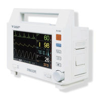
Fukuda Denshi Dynascope 8000 Series Operation Manual (252 pages)
Brand:
Fukuda Denshi
| Category:
Medical Equipment
| Size: 3 MB
Table of Contents
Preface
3
Table of Contents
3
For Safe Operation of the Equipment
4
Important Notice
4
Intended Use of this Equipment
4
Maintenance, Repair, Replacement
4
Contact
5
Expression Used in this Manual
5
Safety Precautions
6
Warning Label
6
Measurement Unit for each Parameter
7
Graphic Symbols
8
Electrical Equipment
11
Precautions for Safe Operation of Medical
11
Precautions about the Maintenance
12
Precautions about Medical Telemetry
13
Precautions about the Pacemaker
15
Defibrillation Safety
16
Imaging
16
Non-Explosion Proof
16
Electrosurgery Safety
17
Accessories and Optional Accessories
18
Peripheral Devices
18
Precautions about the DSL-8001
19
Precautions about the Ventilator Monitoring
26
Components
27
Precautions about Use of the Spo Sensor
27
Precautions for Use of NIBP Cuff
27
Precautions about RTC or Data Backup
28
Precautions about Transportation
28
To Prepare for Emergency Use
28
Electromagnetic Compatibility
29
Precautions for Safe Operation under Electromagnetic Influence
29
Compliance to the Electromagnetic
30
EMC Guidance
30
Emissions
30
Immunity (1)
31
Immunity (2)
31
Recommended Separation Distances
33
Table of Contents
35
Between Portable and Mobile RF
36
Communications Equipment and the DSL-8001 System
36
Preface
36
General Description
43
Chapter 2 Basic Operation
51
Basic Operation for Monitoring
52
Fixed Keys Control
52
Jog Dial Control
53
The Jog Dial Marker
54
Preparation for Monitoring
57
To Turn ON/OFF the Power
58
Turn on the Power
58
Turn off the Power
58
To Start and Stop the Monitoring
59
Preparation before Monitoring
59
At Power on
59
Date/Time Setup
60
Initial Setup
61
Maintenance Menu
61
To the Patient
62
To Start Monitoring
62
To Suspend Monitoring
63
Discharging Procedure
63
Displayed Screen
64
Types of Displayed Screens
64
Home Display
64
Standard Mode
65
Zoom Mode
66
Auto Zoom Mode
67
Icons Displayed on the Window
68
Trend Display
71
Setup Window
72
Alarm Limit Setup Window
72
Window
73
Main Menu
74
How to Display Main Menu
74
Setup Menu
75
Patient Setup
75
Sound Setup
75
Display Setup
75
Alarm Setup
76
Parameter Setup
76
Printing Setup
76
Data Setup
77
Initial Setup
77
Maintenance
77
Alarm Function
78
Alarm Level and Alarm Tone
78
Displayed Message
79
Alarm Setup
79
Alarm Related Setup
79
Parameter Alarm
80
Alarm Behavior Setup
80
Alarm Occurrence
81
To Silence the Alarm
81
To Suspend the Alarm Sound
82
Ventilator Alarm Input
83
Ventilator Alarm Message
84
Printing
85
To Start/Stop the Printing
85
Printing Type
85
Manual Printing
86
Alarm Printing
86
Periodic Printing
86
Trend Printing
87
Header of each Printing
87
Printing Speed
87
To Install the Paper
89
Chapter 3 Vital Application
91
To Acquire ECG Waveform
92
Before Attaching the Electrodes
92
Electrode Placement
93
For 3-Electrode Lead
93
(1 Waveform Monitoring)
93
For 4-Electrode Lead
93
For 5-Electrode Lead
94
Connection to the Patient Monitor
95
Filter Mode Setup
97
Respiration (Impedance Measurement)
98
To Measure the Spo
99
To Measure the NIBP
104
Procedure for Periodic Measurement
107
To Measure the Temperature
109
Probe Type
109
Chapter 4 Monitoring Setup
113
Patient Setup
114
Admit the Patient
114
Patient Classification
114
Pacemaker
115
Monitor Suspend Setup
115
Night Mode
116
Discharge
117
Sound Setup
118
Operating Sound Volume
118
Sync Sound Volume
118
Alarm Sound Volume
119
Boot / Shutdown Sound Volume
119
Other Sound Volume
120
Alarm Sound Pattern
120
Sync Sound Pattern
121
Display Setup
122
Waveform Parameter
122
Sweep Speed
122
Auto Zoom Mode Setup
123
Auto Hide Window Setup
123
Color Setup
124
Alarm Setup
125
NIBP Measurement at Alarm
125
Alarm Limit Display
125
Alarm Limit Setup
126
Printing Setup
128
Printing Speed
128
Manual Printing Setup
129
Output Printer
129
Printing Waveform
129
Printing Duration
130
Delay Time
130
Alarm Printing Setup
131
Alarm Printing
131
Output Printer
131
Printing Waveform
132
Cause for Printing
132
Printing Duration
133
Periodic Printing Setup
134
Periodic Printing
134
Output Printer
134
Printing Waveform
135
Printing Duration
135
Printing Interval
136
Chapter 5 Parameter Setup
137
PR Setup
138
ECG Lead
138
ECG Size
138
Filter Mode
139
PR Source
139
PR Alarm
140
Pacemaker Pulse
141
Spo 2 Setup
143
SEC Alarm
143
Spo 2 Alarm
145
Alarm at NIBP Measuring
146
NIBP Setup
147
Quick Measurement
147
Sight Inflation
148
Pump Operation Mode
148
PR Display
149
Oscillation Graph Display
149
Pressure Setup
150
Notification of Measurement
150
NIBP Measurement Interval Setup
150
NIBP Data Display Time
151
NIBP Alarm
151
RESP Setup
152
RESP Measurement
152
RESP Size
152
RESP Alarm
153
RR Zero Alarm
154
RR Zero Alarm Limit
154
TEMP Setup
155
Temperature Unit
155
TEMP Alarm
155
Trend
158
To Display the Trend
158
Description of the Trend Display
158
Setup for Trend Display
159
Selecting the Display Time Width
160
Selecting the Display Scale
160
Selecting the Parameter
161
Deleting the Trend Data
161
Trend Printing
161
Table
162
To Display the Table
162
Description of the Table Display
162
Setup for Table Display
163
Selecting the Display Interval
164
Selecting the Display Conditions
164
Changing the Display Order
165
Deleting the Table Data
165
Chapter 8 Maintenance
183
Alarm Behavior Setup
190
Night Mode
192
Automatic End Time
193
Automatic Start Time
193
Screen Brightness
194
Volume
194
Handling
196
Handling after Use
196
Handling the Display Panel
196
Storage
197
Storing the Equipment
197
Storing the Recording Paper
197
Cleaning
198
Cleaning the Display Panel
198
Cleaning the Housing
198
Battery
200
Handling the Battery
200
Storage
200
About the Maintenance Check
201
Daily Check
201
Maintenance Check
201
Periodic Check
201
Periodic Replacement
201
Periodic Replacement Parts Information
202
Chapter 6 Function
203
Installation
203
Troubleshooting
204
Ecg
204
Respiration (RESP)
205
Non-Invasive Blood Pressure (NIBP)
206
Arterial Oxygen Saturation (Spo 2 )
209
Chapter 9 Technical Information
217
Technical Information
217
Temperature (TEMP)
221
Vital Alarm
223
List of Setup Items
224
Menu Levels
224
Setup Items
224
Setup Item (Level 1)
225
Setup Item (Level 3)
227
Setup Item (Level 4)
233
Default Settings
234
Parameter
234
Other Setup
236
Initial Setup
238
Message List
239
Vital Alarm
239
Technical Alarm
240
Ventilator Alarm
242
Alarm Output Connector
243
COM1, COM2 Connectors
243
External Connection
243
Other Information
244
Accessories
245
Accessories
246
ECG, Impdance Respiration Measurement
247
Non-Invasive Blood Pressure Measurement
247
Optional Accessories
247
Spo Measurement (COVIDIEN)
248
Temperature Measurement
248
Others
249
Advertisement
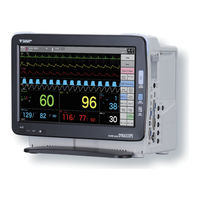
Fukuda Denshi Dynascope 8000 Series Service Manual (274 pages)
Patient Monitor
Brand:
Fukuda Denshi
| Category:
Medical Equipment
| Size: 9 MB
Table of Contents
Preface
5
Table of Contents
5
About the Safety Precautions
6
The Meaning of each Safety Precaution
6
Warning Labels Attached to the Unit
6
Graphic Symbols
8
Equipment
10
Precautions about the Maintenance
12
Precautions about the Network System
13
Medical Telemetry
13
Precautions When Using with Other Equipment
14
Pacemaker
14
Non-Explosion Proof
14
Defibrillator
14
Electrosurgical Instrument
15
MRI (Magnetic Resonance Imaging)
15
Precautions about Connections to Peripheral Devices
16
Precautions for Using the Equipment
17
This System
17
Wired Network (DS-LANII/ DS-LANIII)
27
Wireless Network System
28
RTC and Data Backup
28
Precautions about the Ventilator Monitoring
29
Precautions about the Spo Sensor
29
Precautions about the Masimo Model
29
Precautions about the NIBP Cuff
29
Precautions about Disposing of the Equipment, Accessories, or Components
29
Precautions about Transportation
30
Monitoring after Power Failure
30
To Prepare for Emergency Use
30
Electromagnetic Compatibility
31
Influence
31
EMC Guidance
32
Chapter 4 Operational Description
75
Circuit Description of Mother Board (PCB-7674)
95
Circuit Description of Memory Board (PCB-7675)
99
Power Board (PCB-7676)
101
Circuit Description of Connector Board (PCB-7306)
104
Circuit Description of Extended Board (PCB-7678)
106
Circuit Description of Capacitor Board (PCB-7707)
109
Circuit Description of Main Joint Board (PCB-7709)
109
Circuit Description of AUX Board (PCB-7710)
113
Circuit Description of Lock Sensor Board (PCB-7766)
114
Circuit Description of Module Slot Board (PCB-7759)
114
Circuit Description of Battery I/F Board (PCB-7629)
115
Fan
116
Power Supply Unit (SNP-G125-MF: Skynet)
116
Chapter 7 Assembly Diagram
129
DSC-8410 CPU Unit BLK
130
DSC-8410 Power Supply Unit BLK
132
DSC-8410 Expansion Board BLK
134
DSC-8410 Assembly (1) (Front Case Part)
135
DSC-8410 Assembly (2) (CPU Unit Part)
137
DSC-8410 Assembly (3) (Joint Part, Expansion Module Part)
139
DSC-8410 Assembly (4) (COM/AUX Part, Recorder Part)
141
DSC-8410 Assembly (5) (Power Board Part, Power Supply Unit Part)
143
DSC-8410 Assembly (6) (Rear Case Sheet Metal Part)
145
DSC-8410 Assembly (7) (Rear Case Part)
147
DSC-8410 Assembly (8) (Front/Rear, Stand Part)
149
DSC-8410 Assembly (9) (Expansion Board Part Blank)
151
DSC-8410 Assembly (10) (Super Unit Cover Assembly)
152
DSC-8410 Assembly (12) (Labeling)
156
Attaching the Display Unit (LC-8016TC, LC-8018TC)
158
Installing the HLX-801
162
Chapter 9 Troubleshooting
169
Ecg
170
Respiration
174
Invasive Blood Pressure
176
Spo 2 Measurement (HS-8312N, DS-8007N, HG-820)
178
Spo Measurement (HS-8312M, DS-8007M, HG-810)
180
Non-Invasive Blood Pressure
184
Temperature
189
Cardiac Output (CO)
190
CO 2 Measurement (HCP-800/HCP-810/HCP-820)
193
CO 2 Measurement (HPD-800/HPD-810/HPD-820)
194
Recorder Unit (HR-800)
195
Network Printer
196
Wired Network (DS-LANII/ DS-LANIII)
197
Telemeter (HLX-801)
199
General
200
Remote Control
200
Super Unit
204
Data Transfer Function
205
IB-8004 Input Box
206
Expansion Module
208
Extended Display Unit
209
Ventilator
210
Multigas Unit
211
Svo 2 /CCO Monitor
213
BIS Monitor (A-2000/A-3000)
214
BIS (When HBX-800 Is Used)
215
FLOW-I
219
Invos
219
PC Communication
219
External Media
220
Magnetic Card Reader/Barcode Reader
220
Chapter 10 Maintenance
223
DIP Switch / Rotary Switch Setup
224
DIP Switch Setup
224
Rotary Switch Setup
225
How to Display Test Menu
226
Test Menu
226
Test Menu Description
227
Test Menu Details
229
Handling the Display Panel
235
Storage (Equipment and Recording Paper)
235
Storing the Battery
235
Storing the Recording Paper
235
Cleaning the Touch Panel
236
Cleaning Touch Panel and Housing
236
Cleaning and Disinfecting the Temperature Probe
237
Cleaning the Cardiac Output Relay Cable
237
Cleaning the ECG Lead Cable, Relay Cable
237
Cleaning the Housing
237
Disinfecting the Blood Pressure Transducers
237
Clean NIBP Cuff, Air Hose up
238
Cleaning and Sterilization of Airway Adapter
238
Cleaning/Disinfecting the Spo Sensor
238
Part Replacement
239
Replacement of Short-Term Backup Battery
239
Replacement of Long-Term Backup Battery
244
Daily and Periodic Check
260
Maintenance Check
260
Daily Check Items and Procedures
261
Periodic Check Items and Procedures
262
Gas Measurement Accuracy Check Procedure
267
Handling the Lithium-Ion Battery Pack (BTO-005)
267
Self-Diagnosis Function
271
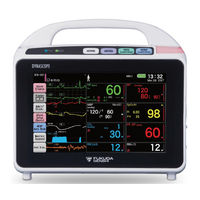
Fukuda Denshi Dynascope 8000 Series Service Manual (188 pages)
Central Monitor
Brand:
Fukuda Denshi
| Category:
Medical Equipment
| Size: 8 MB
Table of Contents
Table of Contents
5
Introduction
6
Important Notice
6
For Safe Operation of the Equipment
6
Intended Use of this Equipment
6
Copyright
6
Maintenance, Repair, Replacement
7
Contact
7
About this Manual
8
Expression Used in this Manual
8
Meaning of the Symbols
8
Indications for the Screens and Keys
8
Restriction of the Function
8
Composition of this Manual
10
System Construction and Installation
10
About the Safety Precautions
12
The Meaning of each Safety Precaution
12
Warning Labels Attached to the Equipment
12
Graphic Symbols
13
Precautions for Safe Operation
14
Precautions for Safe Operation of Medical Electrical Equipment
14
Maintenance
15
Precautions about the Network System
15
Medical Telemetry
15
Bidirectional Wireless Communications Module (TCON) (for USA Only)
16
Precautions When Using with Other Equipment
18
Pacemaker
18
Non-Explosion Proof
18
Defibrillator
18
MRI (Magnetic Resonance Imaging)
19
Precautions for Using the Equipment
19
This System
19
Wired Network System
24
Wireless Network System
24
TCON System (for USA Only)
25
RTC and Data Backup
25
Cables
25
Precautions about the Peripheral Device, Accessories, Optional Accessories
25
Connection to Peripheral Device
25
Fuse
26
Accessories and Optional Accessories
26
Recording Paper
26
Precautions about Disposing of the Equipment, Accessories, or Components
26
Precautions about Transportation
27
Electromagnetic Compatibility
28
Precautions for Safe Operation under Electromagnetic Influence
28
EMC Guidance
28
Telemetry Precautions
32
Declaration of Conformity
33
General Description
40
Composition of the System
40
Features
40
Various Display Configuration
41
Customizable Home Display
41
Individual Bed Display
41
Shortcut Keys
41
Operation Flow
42
Specification/Performance
44
Specification
44
Environmental Conditions
44
Safety
44
Power Supply
45
Usable Life
45
Performance
45
Display
45
Measurement Unit for each Parameter
46
External Connection
48
RS-232C Connector Output Signal
48
COM1 to COM4 Connector
48
Technical Information
48
Settings for each Alarm System
48
Alarm Limit Range for each Parameter
49
Arrhythmia Type
51
Numeric Data Box Size Range
52
Front Side
54
Rear Side
54
Left Side
55
Right Side
56
DS-8900 Main Unit
58
Main CPU Board (PCB-7303)
58
External Connector
60
Internal Connector
64
DS-8900 Alarm Board Assembly
116
DS-8900 LCD Unit Assembly (1)
117
DS-8900 LCD Unit Assembly (2)
118
DS-8900 LCD Unit Assembly (3) <For Europe
119
DS-8900 LCD Unit Assembly (3) <For USA
120
DSC-8510 CPU Assembly
121
DSC-8510 Main Unit Rear Chassis Assembly
122
DS-8900 Extended Board Assembly
123
DS-8900 Main Block Assembly (1)
124
DS-8900 Stand Part Assembly (1)
125
DS-8900 Stand Part Assembly (2)
126
DS-8900 Final Assembly <For Europe
127
DS-8900 Final Assembly <For USA
128
LC-8026T Power Supply Unit Assembly <For Europe
129
LC-8026T Power Supply Unit Assembly <For USA
130
LC-8026T Final Assembly <For Europe
131
LC-8026T Final Assembly <For USA
132
Software Version
134
Software Upgrade
134
DS-8900 (Display Unit) Program Installation
135
LC-8026T Program Installation
135
DS-8900 (Main Unit) Program Installation
136
Measurement Status
141
System Status
141
Printer Status
142
Messages Displayed Inside the Numeric Data Box
143
Pulse Rate (BP Source)
143
Nibp
143
Spo 2 /Spco/Spmet/Sphb
144
PR-Spo 2
144
RR (Impedance)
144
RR (Ventilator)
145
RR (Gas)
145
Gas (MGU-800)
145
Spiro (Mgu-810)
146
Troubleshooting
147
Wired Network (DS-LANIII), TCP/IP Network
147
Telemetry, TCON
147
Bed Register
149
Alarm
149
Display
150
General
151
Recorder Unit (HR-800)
152
Laser Printer
153
CF Card
154
Remote Control
154
EMR Link Function
155
Mouse/Keyboard
155
Slave Monitor
156
Bed Transfer/Exchange
156
Extended Display Unit
157
DIP Switch/Rotary Switch Setup
160
DIP Switch Setup
160
Rotary Switch Setup
161
Test Menu
162
To Display the Test Menu
162
Test Menu Items
163
Maintenance Menu Details
164
Status
164
Main Unit
164
Communication Test
166
DISP CPU Board
167
Test / Adjustment
168
Video I/F
168
Touch Panel
169
Touch Panel Adjustment
169
RTC Setup
170
Storage Storing the Equipment and Recording Paper
171
Storing the Equipment
171
Storing the Recording Paper
171
Cleaning the Touch Panel and Housing
171
Cleaning the Touch Panel
171
Cleaning the Housing
172
Periodic Replacement
172
Periodic Replacement Parts
172
Battery Disposal
173
Replacing Procedure
173
Replacing the Short-Term Backup Battery
173
Service Life of the Short-Term Backup Battery
173
Tools for Replacement
173
Disassembly and Assembly
174
Maintenance Check Daily and Periodic Check
178
About the Maintenance Check
178
Daily Check
178
Periodic Check
178
Periodic Replacement
178
Preface
179
Daily Check Items
179
Daily Check Procedure
179
Periodic Check
182
Preface
182
Service Tools/Measurement Device
182
Periodic Check Item
182
Periodic Check Procedure
183
Advertisement
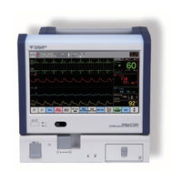
Fukuda Denshi Dynascope 8000 Series Maintenance Manual (154 pages)
Patient Monitor
Brand:
Fukuda Denshi
| Category:
Medical Equipment
| Size: 5 MB
Table of Contents
Table of Contents
3
Preface
9
Introduction
9
Important Notice
9
For Safe Operation of the Equipment
9
Intended Use of this Equipment
9
Copyright
10
Maintenance, Repair, Replacement
10
Contact
10
About this Manual
11
Expression Used in this Manual
11
Composition of this Manual
12
Safety
13
About the Safety Precautions
15
The Meaning of each Safety Precaution
15
Warning Labels Attached to the Unit
15
Graphic Symbols
17
About the Safety Precautions
17
Precautions for Safe Operation of Medical Electrical Equipment
18
Precautions about the Maintenance
19
Precautions about the Network System
20
Medical Telemetry
20
Precautions When Using with Other Equipment
21
Pacemaker
21
Non-Explosion Proof
21
Defibrillator
21
Electrosurgical Instrument
22
MRI (Magnetic Resonance Imaging)
22
Precautions about Connections to Peripheral Devices
23
Precautions for Using the Equipment
23
This System
23
Wired Network (DS-LANII/ DS-LANIII)
31
Wireless Network System
32
RTC and Data Backup
32
Precautions about the Ventilator Monitoring
33
Precautions about the Spo2 Sensor
33
Precautions about the NIBP Cuff
33
Precautions about Disposing of the Equipment, Accessories, or Components
33
Precautions about Transportation
34
Monitoring after Power Failure
34
To Prepare for Emergency Use
34
Electromagnetic Compatibility
34
Precautions for Safe Operation under Electromagnetic Influence
35
EMC Guidance
35
Chapter 1 Installation of the Unit
41
Precautions for Installing the Equipment
41
Operating Environment
41
System Construction
42
Inserting the SD Card
42
Connecting the AC Unit and CO2 Gas Unit
43
Connecting the Recorder Unit (HR-800)
45
Power Source and Ground Connection
48
Power Connection of the Main Unit
48
Equipotential Grounding
49
Installing the Lithium-Ion Battery Pack (BTO-008)
49
Chapter 2 Network System Construction
51
Wired Network System
53
DS-LAN Connection
53
DS-LAN Setup
54
Precautions about Printing/Display
56
Wireless Network
58
Example of Wireless Network Construction
58
Channel ID and Telemetry Wave Setup
58
Chapter 3 Using the External Media
61
Inserting the USB Memory/Sd Card
63
Data Backup/Copy Using the USB Memory/Sd Card
63
Formatting the Full Disclosure Waveform Card
66
Chapter 4 Connection to the External Devices
69
Ventilator Alarm Input
71
Connecting the Ventilator
73
External Device Setup
74
BIS Data Input
75
Connecting the A-2000/A-3000 (Covidien)
75
External Device Setup
75
Setup for the External Device Connection
76
External Device Setup
76
Alarm Output Setup
77
Analog Output Setup
77
Using the Magnetic Card Reader
79
Connecting the Magnetic Card Reader
79
Magnetic Card Reader Setup
79
PC Communication
83
Connection with the System
83
External Device Setup
83
Connection with the Laser Printer
84
Laser Printer Setup
84
Chapter 5 Initial Settings
87
Initial Settings
87
Administrator Setup
88
Key Lock
88
Password Setup
89
Alarm Related Setup
91
Measurement Related Setup
94
User Label Setup
94
Measurement Unit
95
Other Setup
95
User I/F
97
Display/Print Setup
97
Power On/Discharge
101
Shortcut Menu
103
Key Mask
104
Operation Related Setup
105
Quick Menu Setup
107
Setup for the External Device Connection
107
System Setup
107
User Mode Registration
108
About the User Mode
108
To Program the User Mode
109
Chapter 6 Setup Item/Default Value
113
Setup Item
113
Initial Settings
113
Setup Item
120
Initial Settings
120
External Connection (Pin Assignments)
125
Serial Connector Output Signal
125
Status I/O Signal (Status II Connector)
125
Analog Output Signal
126
After Usage/Handling the Equipment
133
After Using the Equipment
133
Display
133
Storing the Equipment and Recording Paper
133
Equipment
133
Recording Paper
134
Cleaning the Equipment and Sensors
134
Touch Panel
134
Housing
135
NIBP Cuff and Air Hose
135
BP Transducer
136
Spo2 Sensor
136
Temperature Probe
136
Cardiac Output Relay Cable
137
Airway Adapter for Capnostat 5
137
Bisx
137
Daily and Periodic Check
141
Maintenance Check
141
Daily Check Items and Procedures
142
Periodic Check Items and Procedures
144
Handling and Storage of Lithium-Ion Battery Pack (BTO-008)
148
CO2 Calibration (HCP-810/HCP-820)
149
Program Version
150
Software Install
150
Fukuda Denshi Dynascope 8000 Series Service Manual (219 pages)
Patient Monitor
Brand:
Fukuda Denshi
| Category:
Medical Equipment
| Size: 8 MB
Advertisement
Related Products
Fukuda Denshi DynaScope 7000 Series
Fukuda Denshi 4R2043
Fukuda Denshi CARDIMAX FX-7202
Fukuda Denshi CardiMax FX-8322
Fukuda Denshi CardiMax FX-8322R
Fukuda Denshi CardiMax8
Fukuda Denshi DS-7001
Fukuda Denshi DS-8200
Fukuda Denshi DS-8400
Fukuda Denshi DS-8900
Fukuda Denshi Categories
Medical Equipment
Transmitter
Monitor
Measuring Instruments
Control Unit
More Fukuda Denshi Manuals
Login
Sign In
OR
Sign in with Facebook
Sign in with Google
Upload manual
Upload from disk
Upload from URL