Table of Contents
Troubleshooting

Subscribe to Our Youtube Channel
Related Manuals for Fukuda Denshi FCP-7101


Summary of Contents for Fukuda Denshi FCP-7101
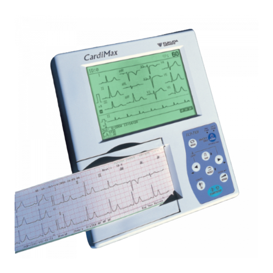
- Page 1 ● Service Manual ● ・ Before setting up/maintenance, please read this service manual carefully. ・ Keep this manual where it can be always referred to.
- Page 2 Copyright © 2004 by Fukuda Denshi Co., Ltd. No part of this document may be copied or transmitted in any form without the prior written permission of Fukuda Denshi Co., Ltd. Printed in China...
- Page 3 Notice This manual contains technical information on the FCP-7101/FX-7102 aimed at Fukuda Denshi service representatives and professional engineers. Before performing maintenance the unit, read the manual carefully and use it to help you work correctly and safely. When you have finished using the manual, store it carefully in a designated location.
- Page 4 ●Servicing Precautions In servicing the FCP-7101/FX-7102, observe the following. DANGER Never remodel the medical electronic equipment. If remodelled, the equipment may not ensure safe operation, thereby causing accidental hazards to the patient and operator. CAUTION The service manual is intended for the service engineers of Fukuda representatives and the technical staff concerned with medical electronic equipment.
- Page 5 If the user operates the instrument as it is, he/she may receive an hazardous accident. ●Equipment Classification The FCP-7101/FX-7102 is classified into the following equipment: 1. Protection against electrical shock Class Ⅱ, Internally powered 2. Type against electrical shock Applied part: Type CF 3.
- Page 6 Overview of the Manual This manual consists of the following 9 chapters. Contents of each chapter are briefly explained below. Chapter 1 Component Names and Functions The locations and functions of the unit's operation panel, switches, connectors, and other components. A list of specifications is also given. Chapter 2 Troubleshooting How to resolve problems that occur, using flowcharts for each symptom.
-
Page 7: Table Of Contents
Contents Notice ···································································································································· ⅰ Safety······················································································································ ⅰ Servicing Precautions ····························································································· ⅱ Equipment Classification ························································································· ⅲ Overview of the Manual ···································································································· ⅳ Chapter 1 Component Names and Functions ······························································· 1-1 Unit (top face) ··················································································································· 1-1 Unit (side, rear, and bottom faces) ················································································· 1-2 Operation panel ················································································································... - Page 8 Memory initialize ································································································3‐21 UPDATE············································································································· 3‐22 Periodical inspections ······································································································3-23 Periodical inspection intervals and precautions ·······················································3-23 List of periodical inspection items ············································································3-23 Safety inspections (4 items)·····················································································3-24 Before checking the leakage current ··································································3-24 Checking the enclosure leakage current (current that flows from the enclosure to the earth terminal of the power outlet) ······························································3-25 Checking the patient leakage current I ·······························································3-25 Checking the patient leakage current III ·····························································3-25...
- Page 9 Paper shaft························································································································ 8‐2 Recorder···························································································································· 8‐3 Upper case (FCP-7101) ···································································································· 8‐4 Upper case (FX-7102) ······································································································· 8‐5 Lower case ······················································································································ 8‐6 General assembly diagram (FCP-7101) ·········································································· 8‐7 General assembly diagram (FX-7102)············································································· 8‐8 Outline view (FCP-7101)··································································································· 8‐9 Outline view (FX-7102) ····································································································· 8‐10 Paper guide······················································································································· 8‐11 50mm Magazine adapter (option)····················································································...
- Page 10 viii...
- Page 11 Chapter Component Names and Functions Unit (top face) ..................1-1 Unit (side, rear, and bottom faces) ............ 1-2 Operation panel ................... 1-3 Specifications list................1-5...
-
Page 13: Unit (Top Face)
Chapter 1 Component Names and Functions Unit (top face) Liquid crystal display, operation panel, and paper magazine are provided on the top face of the unit. (1) Liquid crystal display(LCD) (2) Operation panel (4) Paper magazine (5) Thermal print head (3) Magazine open button (1) Liquid crystal display (LCD) Displays electrocardiogram (ECG) waveforms, patient data, unit status, etc. -
Page 14: Unit (Side, Rear, And Bottom Faces)
Chapter 1 Unit (side, rear, and bottom faces) PATIENT connector and CONTRAST volume are provided on the side of the unit. AC adapter jack, LAN port, and potential equalization terminal are provided on the rear face of the unit. BATTERY PACK compartment is located on the underside of the unit. (11) BATTERY PACK compartment (10) Potential equalization terminal... -
Page 15: Operation Panel
The electrocardiograph can be operated on the operation panel. The LED that indicates the operation status is at the upper right-hand corner of the operation panel. (9) LED (2) [MODE] key Main FCP-7101 Power Charge (1) [POWER ON/OFF] key ON/OFF (stby) - Page 16 Chapter 1 (6) [ID] key Press this key to enter ID. The key serves as the CANCEL key on the setting screen. (7) [SENSE] key Press this key to change the sensitivity of the ECG. The key serves as the ENTER key on the setting screen.
-
Page 17: Specifications List
Component Names and Functions Specifications list Lead Standard 12 leads Standard sensitivity 10mm/mV Sensitivity selection 1/4, 1/2, 1, 2, Auto ±550mV or higher Polarization voltage Frequency response 0.05 to 150Hz Transient characteristics 3.2 sec. (Time constant) Common mode rejection 103dB or more (Standard sensitivity 22mmp-p or lower) Input impedance 50MΩ... - Page 18 Chapter 1 1 - 6...
-
Page 19: Troubleshooting
Chapter Troubleshooting On power supply in equipment (ECG AMP not included)....2-1 On ECG AMP supply voltage.............. 2-2 Problem conditions and corrective action........2-3 Unit doesn't start up when main power is switched ON... 2-4 Battery operations are not executed........2-4 Troubleshooting related to supply voltages ...... -
Page 21: On Power Supply In Equipment (Ecg Amp Not Included)
Chapter 2 Troubleshooting On power supply in equipment (ECG AMP not included) The following concerns the supply voltages in the equipment. This equipment generates various DC power supply voltages (+24, +5, +5VSTB, +3.3V, +3.3VSTB, +1.8V and −24V) inside using the DC power supply, +18V, output by the attached AC adaptor or the DC power supply of the battery. -
Page 22: On Ecg Amp Supply Voltage
Chapter 2 On ECG AMP supply voltage Since the ECG AMP is insulated, power is supplied through the push-pull circuit with a pulse transformer (FT-2155). VTRF: Main power supply of the ECG AMP. Generated through the pulse transformer (FT-2155). Generates +5VDF (+2.5VF) and +3.3VDF. -
Page 23: Problem Conditions And Corrective Action
Maintenance Problem conditions and corrective action CAUTION If any part mounted on the MAIN BOARD (PCB-6950) or other circuit boards seems to be faulty, replacing not the part itself only but the entire circuit board is recommended. CAUTION When checking the circuit voltage and signals to correct a problem, be careful not to cause a short circuit. -
Page 24: Unit Doesn't Start Up When Main Power Is Switched On
Chapter 2 ●Unit doesn't start up when main power is switched ON. Item to Check Method of Checking and Corrective Action Place to Check Power cable Check that the power cable is plugged into the power Power cable outlet and the AC adaptor. Check that the DC plug DC plug is connected to the equipment. -
Page 25: Troubleshooting Related To Supply Voltages
Maintenance ● Troubleshooting related to supply voltages * The following troubleshooting assumes that the fuses F6 and F3 are not blown. Check fuses first when you have a trouble with the supply voltage. Item to Check Method of Checking and Corrective Action Place to Check Check that +3.3V is applied to terminal C312 on the +3.3V... -
Page 26: Failures Related To Charging Operations
Chapter 2 ●Failures related to charging operations Item to Check Method of Checking and Corrective Action Place to Check Power cable Check that the power cable is plugged into the power Power cable outlet and the AC adaptor. Check that the DC plug is DC plug connected to the equipment. -
Page 27: Lcd Does Not Display Or Display Is Abnormal
Maintenance ●LCD does not display or display is abnormal. Item to Check Method of Checking and Corrective Action Place to Check Contrast Contrast adjusting knob Operate the contrast control knob to adjust the LCD P1-2 brightness. REFERENCE Connector Verify that the flat cable of the LCD unit and P1 on Flat cable of LCD unit and P1 the KEY LCD I/F board is securely connected. -
Page 28: Cannot Perform Key Operations
Chapter 2 ●Cannot perform key operations. Item to Check Method of Checking and Corrective Action Place to Check Cable Check that the KEY cable is connected to P2 and the KEY BOARD. Key cable Check that the parts around P2 are properly P5-32 REFERENCE mounted. -
Page 29: Date/Time Changes
Maintenance ●Date/time changes. The clock function is performed by lithium battery (BT1) at all times. The setting of the equipment is backed up for about 5 years, on condition that it is stored at the room temperature. Item to Check Method of Checking and Corrective Action Place to Check Lithium battery... -
Page 30: Recording Paper Is Fed, But Printing And Waveform Recording Are Not Performed
Chapter 2 ●Recording paper is fed, but printing and waveform recording are not performed. Item to Check Method of Checking and Corrective Action Place to Check Connector Verify that the thermal print head cable is securely attached to connector P3 on the MAIN BOARD. Thermal print head cable Verify also that the soldering of connectors P3 is free P5-33... -
Page 31: All 12-Lead Patient Records Appear As Baselines
Maintenance ●All 12-lead patient records appear as baselines. Item to Check Method of Checking and Corrective Action Place to Check Control signal Check that 125kHz rectangular waves are input to IC20 pins 13,15 IC20 pin 13. P5-36 REFERENCE Check also that reversed rectangular waves are input to IC20 pin 15. - Page 32 Chapter 2 2 - 12...
-
Page 33: Maintenance
Chapter Maintenance Cleaning ....................3-1 Cleaning the unit ..............3-1 Replacing the battery................3-2 Update of the software................ 3-4 Self-diagnostics test ................3-5 User self-diagnostics test ............3-6 ECG Test Pattern ..............3-7 Recording Test ..............3-8 Key Test ................3-9 LCD Test ................ - Page 34 Inspection of electrical performance/characteristics ....3-26 Hardware inspections (10 items) ...........3-28 Periodical inspection(2) record............3-30...
-
Page 35: Cleaning
Chapter 3 Maintenance Cleaning ●Cleaning the unit Moisten gauze or absorbent cotton with medicinal alcohol or neutral detergent, and wring tightly; then wipe off the enclosure. CAUTION Prevent chemicals and other liquids from getting inside the unit and connectors. Electrical equipment can short and get damaged. -
Page 36: Replacing The Battery
Chapter 3 Replacing the battery DANGER Before replacing the battery, make sure to turn the power OFF and unplug the power supply cord from the AC adapter. 1. Turn OFF the main power switch of the unit and unplug the DC plug. 2. - Page 37 Maintenance 4. Install a new battery. Insert the battery cable connector to the power supply terminal, and place the battery inside the battery case and mount the battery compartment cover. Compartment cover Battery Connector NOTE If the battery compartment cover does not fit well, reinstall the battery and battery cable in the battery case.
-
Page 38: Update Of The Software
To update the software, it must be installed in the PC in advance. 1. Connect the LAN port of the equipment and the PC with a LAN cable. FCP-7101/FX-7102 LAN cable To LAN port 2. Carry out PROGRAM UPDATE of MAKER MAINTENANCE. (See manufacturer self-diagnosis test.) -
Page 39: Self-Diagnostics Test
Maintenance Self-diagnostics test The self-diagnostics test function is classified into two types: user self-diagnostics test and manufacturer self-diagnostics test. The user self-diagnostics test is used for a daily check by the user. The manufacturer self-diagnostics test is used for checking and adjusting the unit in a production process or during product inspection, and for the maintenance by the manufacturer. -
Page 40: User Self-Diagnostics Test
Chapter 3 ●User self-diagnostics test Push the [MODE] key and select [SET UP] using the [→] key. Push the [↓] key to display the pull-down menu. Select [MAINTENANCE] from the menu using the [ ↑ ] [ ↓ ] key. Then push the [ENTER] key, and the [SETUP MODE (MAINTENANCE)] screen is displayed. -
Page 41: Ecg Test Pattern
Maintenance ECG Test Pattern This section explains how to select the built-in electrocardiogram (ECG) test pattern waveform to use during an operation check or demonstration. 1. Select [ECG TEST PATTERN] on the [SETUP MODE (MAINTENANCE)] screen, and the ECG TEST PATTERN selection screen is displayed. 2. -
Page 42: Recording Test
Chapter 3 Recording Test This test is performed to check the recording status. 1. Select [RECORDING TEST] on the [SETUP MODE (MAINTENANCE)] screen, and the diagnosis screen is displayed. Push the [MODE] key to return to the SETUP pull-down menu selection screen. 2. -
Page 43: Key Test
Maintenance Key Test This test is performed to check the key operation. 1. Select [KEY TEST] on the [SETUP MODE (MAINTENANCE)] screen, and “Push [START/STOP] 2 times” message appears. Push the [MODE] key to return to the SETUP pull-down menu selection screen. 2. -
Page 44: Lcd Test
Chapter 3 LCD Test This test is performed to check the LCD for missing dots, its gradation, etc. 1. Select [LCD TEST] on the [SETUP MODE (MAINTENANCE)] screen, and the diagnosis screen is displayed. Push the [MODE] key to return to the SETUP pull-down menu selection screen. -
Page 45: Buzzer Test
Maintenance Buzzer Test This test is performed to check the tone, volume, etc. of the speaker. 1. Select [BUZZER TEST] on the [SETUP MODE (MAINTENANCE)] screen, and the diagnosis screen is displayed. Push the [MODE] key to return to the SETUP pull-down menu selection screen. -
Page 46: Manufacturer Self-Diagnostics Test
Chapter 3 ●Manufacturer self-diagnostics test Select [MAKER MAINTENANCE] on the [SETUP MODE (MAINTENANCE)] screen and enter the password, and the [MAKER MAINTENANCE] screen is displayed. Manufacturer self-diagnostic test can be performed on this screen. Manufacturer self-diagnostic test is usually performed by the personnel of the manufacturer in charge of maintenance. - Page 47 Maintenance 2. Enter the password (9001) using the up/down/right/left key and push the [ENTER] key, and the [MAKER MAINTENANCE] screen appears, allowing you to perform manufacturer self-diagnostic test. Select a desired diagnostic item to go to the corresponding diagnosis screen. 3.
-
Page 48: Status Test
Chapter 3 Status Test This test is performed to check the function of displaying each status of the hardware. 1. Select [STATUS TEST] on the [MAKER MAINTENANCE] screen, and the following screen is displayed. 2. The following status information is displayed in [STATUS TEST]. Thermal head temperature •... -
Page 49: Ecg A/D Data
Maintenance ECG A/D DATA The data (A/D value) input to ECG AMP can be displayed. 1. Press the [←] or the [→] key to switch channels. 3 - 15... -
Page 50: Lan Test
Chapter 3 LAN Test This test is performed to check the function of the LAN. 1. Select [LAN TEST] on the [MAKER MAINTENANCE] screen, and the following screen is displayed. 2. Using the [←], [→], [ ↑ ], or the [ ↓ ] key, enter the IP address of the ECG and that of the HOST. -
Page 51: Memory Test
Maintenance Memory Test This test is performed to check the read/write status of the SDRAM. 1. Select [MEMORY TEST] on the [MAKER MAINTENANCE] screen, and the following screen is displayed. 2. Push the [START/STOP] key to start the memory test. 3. -
Page 52: Rom Write Test
Chapter 3 ROM WRITE Test Read/write test of FLASH ROM can be performed. 1. Select [ROM WRITE TEST] on the [MAKER MAINTENANCE] screen, and the following screen appears. 2. Push the [START/STOP] key to start the ROM WRITE TEST. 3. Push the [START/STOP] key once again to exit the ROM WRITE TEST. 3 - 18... -
Page 53: Recorder Test
Maintenance Recorder Test The recorder test is a function of checking the thermal head for missing dots and verifying the printing condition. 1. Select [RECORDER TEST] on the [MAKER MAINTENANCE] screen, and the following screen is displayed. 2. Select the pattern to be printed using the right/left key. Pattern Process Prints dot pattern. - Page 54 Chapter 3 3. Push the [START/STOP] key to start a recorder test. Select transfer speed using the right/left key while printing is underway. 5mm/S 10mm/S 12.5mm/S 25mm/S 50mm/S 4. Push the [START/STOP] key once again to terminate the recorder test. 3 - 20...
-
Page 55: Memory Initialize
Maintenance Memory Initialize The embedded memory can be initialized following the procedure shown below. 1. Select [ROM INITIALIZE] on the [MAKER MAINTENANCE] screen, and the following screen is displayed. 2. Push the [START/STOP] key to start initializing the embedded memory. 3. -
Page 56: Update
Chapter 3 Update The software installed in the ECG can be updated following the procedure shown below. 1. Select [PROGRAM UPDATE] on the [MAKER MAINTENANCE] screen, and the following screen is displayed. 2. Enter the IP address of the ECG and that of the HOST, using the [←], [→], [ ↑ ], or the [ ↓... -
Page 57: Periodical Inspections
Maintenance Periodical inspections To maintain the unit's functions and performance, periodical inspections are required. The inspections explained in this section should be performed by service representatives who have sufficient technical knowledge. ●Periodical inspection intervals and precautions Inspection item Description Periodical inspection interval Periodical inspection should be performed at least once a year. -
Page 58: Safety Inspections (4 Items)
Chapter 3 ● Safety inspections (4 items) To assure safety of medical equipment, testing methods and measurement equipment are prescribed in the safety test standards with respect to leakage current that affects human body. To perform inspections, make the setting and pass/fail evaluation using a leakage current gauge that meets the requirements for measurement of medical equipment. -
Page 59: Checking The Enclosure Leakage Current
Maintenance Checking the enclosure leakage current (current that flows from the enclosure to the earth terminal of the power outlet) Measurement condition of the enclosure leakage current It is required to measure the enclosure leakage current under two conditions: normal condition and single fault condition. Judgment criteria Normal state 0.1 mA or lower... -
Page 60: Inspection Of Electrical Performance/Characteristics
Chapter 3 ●Inspection of electrical performance/characteristics 1.Sensitivity Check that the recorded amplitude is within 10±0.2 mm after 1 mV of voltage is added to the unit by the standard voltage generator. Change the sensitivity selector switch to 1/2, 1/4, and 2, and check that standard sensitivity is within ±5%. - Page 61 Maintenance 5.Counter electrode voltage Check that the change in the recorded sensitivity is within ±5% when ±550 mV of DC voltage is imposed to the input of the Electrocardiograph. Check that the change in the recorded sensitivity is within ±5% when ±550 mV of DC voltage is imposed between the two input terminals of the Electrocardiograph and the RF(N) electrode fitting.
-
Page 62: Hardware Inspections (10 Items)
Chapter 3 ●Hardware inspections (10 items) WARNING If, during a hardware inspection, you notice damage or other abnormality, immediately stop using the given unit; then replace the defective part, replenish, or make proper repairs. Failure to repair the unit can lead to a serious accident. Do not replace the part nor carry out refilling or the like but change the hardware (MAIN BOARD, for ex.) found faulty. - Page 63 Maintenance Checking the switches Description Check for unsmooth operation, damage, and rattling. Checking the recorder Description Check that recording operation is smoothly performed and no abnormal noise exists. Checking the electrodes Description Check the electrodes for corrosion, and their chip-mounting area for wear, safety defects, malfunctional operation, and damage.
-
Page 64: Periodical Inspection(2) Record
Chapter 3 Periodical inspection(2) record Remarks Procedure/measurement value Judge- Item Description (Repair Acceptance standard ment required 1. Power supply cord, patient cable, etc. Any flaws or damages? OK・NG Cables 2. Limb electrode, chest electrode, etc. Any contamination or rust adhered? OK・NG Electrodes 3. - Page 65 Maintenance Remarks (Acceptance Measurement Description Judgement (Repair standard) value required 1. Enclosure leakage Normal condition (0.1m or less) OK・NG current Single fault condition (0.5mA or less) OK・NG 2. Patient leakage Normal condition (0.01mA or less) OK・NG current I Single fault condition (0.05mA or less) OK・NG 3.
- Page 66 Chapter 3 3 - 32...
-
Page 67: Disassembly
Chapter Disassembly Removing the LCD ..............4-1 Removing the enclosure cover ..........4-2 Removing the recorder unit ............4-3 Removing the main board ............4-4... -
Page 69: Removing The Lcd
Disassembly Removing the LCD 1. Press the magazine open button and remove the paper magazine. Paper magazine Magazine open button 2. Remove the mounting screws (four). Mounting screw 3. Open the top cover. 4. Remove the nuts (three) fastening the LCD. 5. -
Page 70: Removing The Enclosure Cover
Chapter 4 6. Remove the LCD cable connected to connector P1. LCD module LCD cable Shield plate Removing the enclosure cover 1. Remove the LCD REFERENCE For details on removing procedures, see page4-1, “Removing the LCD”. 2. Remove the KEY cable connected to connector P2. Enclosure cover Key cable 4 -2... -
Page 71: Removing The Recorder Unit
Disassembly Removing the Recorder unit 1. Remove the LCD. REFERENCE For details on removing procedures,see page4-1”Removing the LCD”. 2. Remove the enclosure cover. REFERENCE For details on removing procedures, see page4-2”Removing the enclosure cover”. 3. Remove the cables connected to connectors P3, P4, P5 and P6. 4. -
Page 72: Removing The Main Board
Chapter 4 Removing the main board CAUTION To prevent damage by static electricity,eliminate static electricity from your body before touching the board. 1. Remove the LCD REFERENCE For details on removing procedures,see page 4-1 ”Removing the LCD”. 2. Remove the enclosure cover. REFERENCE For details on removing procedures, see page 4-2 ”Removing the enclosure cover”. - Page 73 Chapter Electric Circuit Diagrams Overall block diagram of unit (AC adaptor not included) ....5-1 MAIN BOARD block diagram ............. 5-3 MAIN BOARD (PCB-6950) circuit ..........5-5 1.Digital logic block ..............5-5 CPU section................ 5-5 FPGA section..............5-5 Memory section ..............5-6 KEY I/F section ..............
- Page 74 SENSOR I/F /MAGAZIN UP SENSOR I/F MOTOR I/F /JTAG I/F block ..........5-34 ECG AMP block (Differential amplification, multiplexer section) ......5-35 ECG AMP block (ADC,CPLD and POWER section) .....5-36 MAIN POWER SUPPLY +24V block ........5-37 CHARGE block ..............5-38 +5V /+3.3V /+1.8V Power generation block ......5-39 POWER STATUS block............5-40 POWER / CHARGE ERROR block ........5-41 +3.3VSTB / +1.8V POWER ON RESET block ......5-42...
-
Page 75: Overall Block Diagram Of Unit (Ac Adapter Not Included)
Chapter 5 Electric Circuit Diagrams Overall block diagram of unit (AC adaptor not included) The FCP-7101/FX-7102 is equipped with the following four boards. 1.MAIN BOARD (PCB-6950) 2.KEY BOARD (PCB-6949) 3.SENSOR BOARD (PCB-6948) 4.MAG UP BOARD (PCB-6951) The MAIN BOARD (PCB-6950) amplifies the ECG signals input from patient connectors... - Page 76 5 - 2...
-
Page 77: Main Board Block Diagram
Electric Circuit Diagrams ●MAIN BOARD block diagram Power Supply CPU (SH7727) FROM AC ADAPTER Super H Cache +18V +18V 32MHz CPU Core 16kByte +18V→+24V DC/DC CKIO +24V DMAC INTC H-UDI +24V→+3.3V DC/DC +24V→+5V DC/DC +5.0V KEY INPUT SIGNAL +3.3V +5V→+1.8V DC/DC Peripheral bus controller... - Page 78 5 - 4...
-
Page 79: Main Board (Pcb-6950) Circuit
Electric Circuit Diagrams ●MAIN BOARD (PCB-6950) circuit The main board consists of the following major circuit blocks. 1. Digital logic block 2. ECG AMP block 3. Power supply block 1. Digital logic block CPU section The CPU adopting SH7727 carries out processing for basic operations of ECG such as display of ECG waveforms and recording. -
Page 80: Memory Section
MEMORY section The memory section uses a flash ROM and a SDRAM. The flash ROM adopting TE28F640J3A-120 (64Mbits) is used for program storing, function setting storing, and also used as waveform work area. The SDRAM adopting μPD45128163G5-A75-9JF (128Mbits) is used for program storing and as waveform work area. - Page 81 Electric Circuit Diagrams LAN CONTROLLER section The LAN controller section controls LAN. LAN is used to transmit waveforms recorded with this instrument to outside and when updating the software. IC55 AA[0..8] LAN91C96 (5,6) AA[0..23] TPERXP TPERXN TPETXP TPETXN TPETXDP TPETXDN AB[9..23] (5,6) AB[1..23]...
-
Page 82: Key I/F Section
KEY I/F section The section interfaces with signals input from the keys on the operation panel and buttery control signals. (21) +3.3V D8 1PS302 R1881.0KF +3.3V 1mV_KEY_L +3.3V D9 1PS302 EXBD10C103J R1891.0KF LEFT_KEY_L +3.3VSTB +3.3V D10 1PS302 BLM18RK102SN1D R1901.0KF RIGHT_KEY_L BLM18RK102SN1D BLM18RK102SN1D +3.3V... -
Page 83: Thermal Head Control Section
Electric Circuit Diagrams Thermal head control section The thermal head control section outputs thermal head signals from the FPGA to the thermal head. A buffer for level conversion and R and L are connected as filters to each signal line. The section is also provided with a circuit that generates overheat detection signals to prevent overheating of the thermal head. -
Page 84: Real Time Clock
Real time clock The RTC-4574SAA equipped with a 32.768-kHz crystal oscillator is used as a device for the real time clock. The real time clock operates with a lithium battery (BT1). If a lithium battery is not mounted, the clock does not operate. -
Page 85: Reset Circuit Section
Electric Circuit Diagrams Reset circuit section The reset circuit section uses M62733ML as a reset IC. The whole system is reset 100msec after the supply voltage reaches +2.87V at the reset IC. +3.3V +3.3V M62733ML +3.3V 10KF IC6A VOUT When the supply voltage 電源が+2.87Vになっ... -
Page 86: Sensor Control Section
Sensor control section Two types of sensors are provided, a magazine up sensor and a mark sensor. Signals of the magazine up sensor are output from pin No. 2 of the connector P4. If the magazine opens, the switch is turned off, and an “L” level signal is transmitted to the FPGA. -
Page 87: Motor Control Section
Electric Circuit Diagrams Motor control section The motor control section is in charge of controlling ON/OFF of the torque of the motor. IC22 PHASE_A PHASE_B +3.3V 10KF HD74ACT244 R2637.5KF MVREF0 +3.3V PDTC124EU 10KF R2703.0KF MVREF1 IC21 PDTC124EU PHASE A PHASE B I0 A I1 A R2647.5KF... -
Page 88: Lcd Voltage Generating Section
LCD voltage generating section The section generates LCD voltage (–24V). The use of variable resistor allows the contrast to be adjusted. +3.3V 0.51F(0.5W SR) C178 680pFBJ LPC4045TE 101K MC34063AD SL03 0.1uFFZ R79 3.24KF C179 22UF/50V(C) 62KF 20KF CONTRAST 20KF DTC124EUA 2SA1163 VEPWC R480100F... -
Page 89: Ecg Amp Block
Electric Circuit Diagrams 2. ECG AMP block The following is a block diagram of ECG AMP. First-stage amplifier Second-stage amplifier Patient Multi- connector plexer Photo- CPLD coupler Power Pulse trans- voltage former Generating section ECG signals input from patient connectors go through the input protection section and enter the first-stage amplifier (differential amplifier), where each signal for right arm, left arm, and chest 1 to chest 6 undergoes differential amplification with a signal for left leg. -
Page 90: Power Supply Block
3. Power supply block The following is a block diagram of the power supply block. AC90~264V Adapter 47~63Hz +18V Charger (CV/CC) DC-DC converter +24V DC-DC converter +3.3V +3.3V Power control signal DC-DC converter POWER +3.3V Ni-MH CONTROL BATTERY +5.0V (9.6V) (3700mAh) DC-DC converter... -
Page 91: Power Voltage Generating Section
Electric Circuit Diagrams Power voltage generating section The section generates the following power supply voltages. (1) +24V (2) +5V (3) +3.3V (4) +1.8V (5) +3.3VSTB (Standby power supply) (6) +5V STB (Standby power supply) (7) +24V (For thermal head) (1) +24V The +24V voltage, which is generated from the +18V voltage input from the AC adaptor, is used as the drive voltage of the motor driver. - Page 92 (2) +5V, (3) +3.3V, (4) +1.8V The +5V and +3.3V voltages are generated from the +24V voltage. The +1.8V voltage, which is generated from the +5V voltage, is used as the core voltage of the CPU and the FPGA. IC47 LM2674M-5.0 +24V +5V output source...
- Page 93 Electric Circuit Diagrams (5) +3.3VSTB (Standby power supply) The +3.3V standby power supply used when the DC plug or battery is connected is generated from the +24V voltage or the battery pack voltage. The +3.3VSTB is supplied for the IC of the power supply block. D46A BAS28 IC62...
-
Page 94: Battery Charging Section
Battery charging section The section charges the battery with a charging IC. It also outputs signals that indicate the battery status (charging underway). JP35 +5VSTB 1PS184 CHGSTS (20) BZX84-B5V6 IC43 NJM78L05UA C310 C305 C152 12KF R396 R228 33uF/10V(C) 4.7UF(50V) 0.01UFFZ 150KF 100F 2SK2112... -
Page 95: Power Control Section
Electric Circuit Diagrams Power control section The section monitors the temperature and the voltage of the battery, and transmits the status with various signals. (8,13,18) (13,14,18) VBAT(P) +5VSTB 1PS184 R429 470KF R433 620F R128 R129 3.9KF 39KF R415 R428 470KF R430 R255 150KF... -
Page 96: Key Board (Pcb-6949) Circuit
●KEY BOARD (PCB-6949) circuit The circuit is equipped with key switches for operating this instrument and the LED that indicates the battery status. +3.3STB SW1 SKRAAAE010 SW2 SKRAAAE010 +3.3STB SW3 SKRAAAE010 1mV_KEY LEFT_KEY SW4 SKRAAAE010 RIGHT_KEY RESET_KEY SW5 SKRAAAE010 MODE_KEY START_KEY SW6 SKRAAAE010 SENSE_KEY... -
Page 97: Sensor Board (Pcb-6948) Circuit
Electric Circuit Diagrams ●SENSOR BOARD (PCB-6948) circuit The circuit is equipped with a sensor that detects the mark position. TO MAIN BOARD SENSOR CABLE MARK SENSOR BOARD PCB-6948 LED1 MARK-E DETECT-E EE-SY125 SENSOR-COM LED_DRIVE DF13B-5P-1.25V(21) DF13-5S-1.25C DF4-5P-2C LED2 EE-SY125 ●MAG BOARD (PCB-6951) circuit The circuit is equipped with a switch that detects open/close status of the magazine. -
Page 98: Ac Adaptor Block Diagram
AC adaptor block diagram The following is a block diagram of the AC adaptor. The input of the AC adaptor is worldwide capable, allowing 90V to 264V AC to be input. The +18V voltage generated with the AC adaptor is supplied to this instrument with a power jack. -
Page 99: Main Board Circuit Diagrams (Pcb-6950)
MAIN BOARD Circuit Diagrams (PCB-6950A) ●Power connection table No.1 MAIN02 MAIN03 MAIN04 MAIN05 MAIN06 MAIN07 MAIN08 MAIN09 MAIN10 ECG11 ECG12 POW13 POW14 POW15 POW16 POW17 POW18 POW19 POW20 POW21 MAIN02.SCH MAIN03.SCH MAIN04.SCH MAIN05.SCH MAIN06.SCH MAIN07.SCH MAIN08.SCH MAIN09.SCH MAIN10.SCH ECG11.SCH ECG12.SCH POW13.SCH POW14.SCH POW15.SCH... - Page 100 ● P ower connection tableNo.2 TABLE TYPE +24V +18V VTRF +5VDF +5VSTB +3.3V +3.3VA +3.3VDF +3.3VSTB +3.3VL +2.5VF -2.5VF +1.8V E25F 74HC3G14DP IC2,5,18 74LVC244APW IC3,58 74HC08PW LM2904PWR IC14,15 LM2904PWR IC16,17 LM2904PWR IC49 LM2904PWR IC51 74AHCT14PW IC19 HD74ACT244TTP-20DA IC20,22,70 TLC2264CPW IC23,24,25,26,27 MAX4564EUA IC30 HCPL2601 #300...
- Page 101 ●POWER / CAPACITOR / RESET IC / CLOCK / LCD POWER block +3.3V +1.8V C163 4.7UF/6.3V(T)3 C104 C287 C336 C337 0.01UFFZ 0.1uFFZ 0.1uFFZ 0.1uFFZ C181 C180 C160 C161 0.01uFBJ 0.01uFBJ 4.7UF/6.3V(T)3 4.7UF/6.3V(T)3 +3.3V MG-5100SA-FD VDD1 VDD2 CLKA +3.3V CLKB 20MHz CLKC LAN_CLK CLKD...
-
Page 102: Cpu Block
●CPU block A[0..23] A[0..23] +1.8V D[0..15] D[0..15] (5,6,7) POWER_KEY (21) C47 0.1uFFZ 1mV_KEY_L LEFT_KEY_L RIGHT_KEY_L C182470pFCHJ RESET_KEY_L MODE_KEY_L START_KEY_L C48 0.1uFFZ SENSE_KEY_L AC_FAIL_L (20) 0.1uFFZ CPU_CLK C183 LANPWDOWN_L R131 R130 10KF 470pFCHJ (5,6) CKIO ID_KEY_L POWER_OFF_L (21) (20) THERMAL_ON RTCDAT RTCCLK +3.3V PTJ[4]... -
Page 103: Fpga Block
●FPGA block +3.3V +1.8V +3.3V DRAK_L R382 C190 C191 C192 C193 C168 C169 C170 C171 1.0UF/16V(T)3 1.0UF/16V(T)3 1.0UF/16V(T)3 1.0UF/16V(T)3 4.7UF/6.3V(T)3 4.7UF/6.3V(T)3 4.7UF/6.3V(T)3 4.7UF/6.3V(T)3 10KF DMAREQ_L C142 C141 C140 C139 C138 C137 C136 C135 AA[1..8] (6,7) AA[0..23] PDTC124EU 0.01UFFZ 0.01UFFZ 0.01UFFZ 0.01UFFZ 0.01UFFZ 0.01UFFZ... -
Page 104: Memory Block
●MEMORY block A[0..23] AA[0..23] AB[1..23] D[0..15] A[0..23] AA[0..23] (5,7) AB[1..23] (5,7) (4,5,7) D[0..15] R150 R159 R151 R160 R152 R161 R153 R162 R110 R154 R163 R111 R155 R164 R112 R156 R165 R113 R157 R166 R114 R158 R167 R115 R168 AB10 R116 R169 AB11 R117... -
Page 105: Lan Control Block
●LAN CONTROL block +3.3V NFM2012P13C474F +3.3VL +3.3V C323 C324 C328 0.1uFFZ 0.1uFFZ 4.7UF/6.3V(T)3 C325 C330 C326 C329 C333 C327 C334 0.1uFFZ 0.01uFBJ 0.1uFFZ 4.7UF/6.3V(T)3 0.01uFBJ 0.1uFFZ 0.01uFBJ IC55 LAN91C96 AA[0..8] (5,6) AA[0..23] TPERXP TPERXN TPETXP TPETXN TPETXDP TPETXDN AB[9..23] (5,6) AB[1..23] TXLED RXLED... -
Page 106: Lcd I/F / Rtc / Led Block
●LCD I/F / KEY I/F / RTC / LED block IC70 HD74ACT244 +3.3V BLM18RK102SN1 R240 LCD0 BLM18RK102SN1 R241 LCD1 BLM18RK102SN1 R246 SL03 LCD2 BLM18RK102SN1 R242 IC13 LCD3 BLM18RK102SN1 R247 SL03 (3,4,5,6,21) RESET_L BLM18RK102SN1 R243 RTCCE LCD I/F BLM18RK102SN1 R244 R207 BLM18RK102SN1 R245 2.0KF... -
Page 107: Thermal I/F Block
●THERMAL I/F block 20KF THERMAL_TEMP +2.5V R235 1.0MF R262 IC15A 10KF 7.5KF LM2904PWR +1.25V 20KF OVH_L 10KF IC15B +3.3V 1PS302 LM2904PWR 0.1uFFZ 0.1uFFZ +3.3V 10KF IC20D R248 BLM18RK102SN1 1PS302 STRB +24V_THERMAL +3.3V HD74ACT244 C296 THERMAL I/F 0.1U 50V(1608) 10KF IC20C R249 BLM18RK102SN1 TDOTCLK... -
Page 108: Sensor I/F /Magazin Up Sensor I/Fmotor I/F /Jtag I/F Block
●SENSOR I/F / MAGAZIN UP SENSOR I/F / MOTOR I/F / JTAG I/F block MAGAZINE UP SENSOR CN +3.3V マガジンアップセンサCN +3.3V IC2A SW-COM IC5C 74HC3G14DP SW-ON +3.3V 74HC3G14DP R239 +3.3V DF13B-2P-1.25V(21) 510F 10KF 0.1uFFZ HEADUP_L D18 1PS302 IC16A MARK/RECORDING PAPER SENSOR CN +3.3V マーク/記録紙検出センサCN IC16B... - Page 109 ●ECG AMP block (Differential amplifition, multiplexer section) IC23A R5 2.0KF R_F_off (11) IC26A E25F TLC2264C R316 BLM15AG102SN1 TLC2264C 10KF R340 R293 C208 24KF 3.3KF C2551.0UF R365 R304 C228 300MM 150P 13KB C246 C236 10KF 0.22 3.5M R357 FMW2 E25F E25F 3.3KB R324 39KB...
-
Page 110: Ecg Amp Block (Adc,Cpld And Power Section)
●ECG AMP block (ADC, CPLD and POWER section) +2.5VF +5VDF +5VDF +2.5VF +2.5VF +3.3V (11) ECG_SIG IC35A R377 IC33 OPA2350EA 510F R427 IC38 IC20H IC37 10KF R376 10KF HD74ACT244 1.2KF SCLK AD_DATA VTRF C196 AD_CS_L 1.0UF/16V(T)3 HCPL2601 +2.5VF TLC3541DGK +3.3VDF 0.1uFFZ C269 +3.3VDF... -
Page 111: Main Power Supply +24V Block
●MAIN POWER SUPPLY +24V block (8,16,18) VCHG (14) CDRH127/LD-680MC +24V output source +24Vの出力元 +24V CDRH127/LD-680MC 451003 D3FS4A 2DC-0005D100 R395 DF10SC4M (AC ADAPTER) 150KF IC42 PSMN010-55D SUPON R394 POWON SYNC/SHDN* 100F R403 (15,17,19,21) 33KF PGND R412 0.01F(1W) D55 CRZ24 C341 0.1U 50V(1608) 0.1U 50V(1608) 0.1U 50V(1608) SL03... -
Page 112: Charge Block
●CHARGE block R196 R422 1.0KF(1608) 2.7KF(1608) 1PS184 (13) VCHG VBAT(P) (13,16,18) CDRH127/LD-680MC R417 D3FS4A 1.5KF 2SJ529 2SC2873 BZX84-B16 C294 C301 D28 D3FS4A C202 100UF/35V 100UF/35V 1000pFCHJ 1PS184 JP35 +5VSTB 1PS184 CHGSTS (20) BZX84-B5V6 IC43 NJM78L05UA C310 C305 C152 33uF/10V(C) 12KF R396 R228 4.7UF(50V) -
Page 113: 3.3V /+1.8V Power Generation Block
●+5V / +3.3V / +1.8VPower generation block IC47 LM2674M-5.0 +24V +5V output source +5Vの出力元 C153 0.01UFFZ CDRH127/LD-820MC (19) 5VON ON/OFF* R406 3.3KF C281 0.1U 50V(1608) D3FS4A 0.01UFFZ LED4 C311 0.1uFFZ 220UF/35V D3FS4A SML-210MT IC46 LM2674M-3.3 +3.3V output source +3.3Vの出力元 C154 0.01UFFZ +3.3V CDRH127/LD-680MC... -
Page 114: Power Status Block
●POWER STATUS block (8,13,18) (13,14,18) VBAT(P) +5VSTB 1PS184 R429 470KF R433 620F R128 R129 3.9KF 39KF R415 R428 470KF 150KF R430 R255 10KF 10KF 470KF 15KF R268 R127 22KF 150KF 10KF 10KF IC48B R397 BAT>=14.4V_L (17) 150KF R393 220KF LM339PWR IC48A IC48D (13,14) -
Page 115: Power / Charge Error Block
●POWER / CHARGE ERROR block IC53A IC19A IC56A (16) BAT>=14.4V_L (16) BAT>=70_L BATERR (20) 74AHCT00PW 74AHCT14PW 74AHCT02PW IC56B IC19B IC53B IC19D (18,20) BATDET CHGENA (14) 74AHCT02PW 74AHCT14PW 74AHCT00PW 74AHCT14PW IC56C (13,15,19,21) POWON IC19C 74AHCT02PW (16,20) ACDET IC53C IC19E IC53D 74AHCT14PW PWRFAIL (20) (16) -
Page 116: Vstb / Power On Reset Block
●+3.3VSTB / POWER ON RESET block D46A BAS28 IC62 S-873325BUP-ALA +24V D44A D43B D43A +3.3VSTB 100F R229 VOUT BAS28 BAS28 BAS28 +3.3VSTBの出力元 +3.3VSTB output source PDTC124EU 2SC2873 PDTA124EU C297 C298 0.1U 50V(1608) 0.1U 50V(1608) Q44 2PC4081R C314 33uF/10V(C) C307 4.7UF(50V) C156 C157 D45B... -
Page 117: Battery On Control/ Thermal Powergeneration Block
●BATTERY ON CONTROL/ THERMAL POWERGENERATION BLOCK IC59A 74LVC240APW IC57D POWON (13,15,17,21) BATON (13) SN74LV02APW +3.3VSTB IC60C IC59H R436 74LVC240APW SN74LV132APWR 300KF 5VON (15) R435 R431 470KF 820KF R401 D48A R197 150KF 1.0KF BAS28 IC61A D48B 0.1uFFZ BAS28 (16) VBATOP TLC393IPWLE CMPREF (18) R402... -
Page 118: Power-Main I/F Block
●POWER-MAIN I/F block +3.3V 10KF IC3B PDTC124EU (17) PWRFAIL AC_FAIL_L 74LVC244APW IC58E 74LVC244APW R200 1.0KF (14) CHGSTS CHARGE_ON IC58F 74LVC244APW R201 1.0KF (17) BATERR BATT_ERR_ON IC58G 74LVC244APW IC3A 74LVC244APW R202 1.0KF (16,17) ACDET AC_DETECT IC58H 74LVC244APW IC3C 74LVC244APW 1.0KF R203 (17,18) BATDET BATT_STS... -
Page 119: Power On/Off Control Block
● POWER ON/OFF CONTROL block IC3E 74LVC244APW R232 100F POWER_KEY (STB) +3.3VSTB D24 1PS302 +3.3VSTB IC59G IC59E IC69A 74LVC240APW 74LVC240APW POWON (13,15,17,19) (STB) R231 100F (STB) +3.3VSTB 0.1uFFZ 10KF TC7W74FU IC59F 10KF 74LVC240APW R233 100F (STB) (18) POW_ON_RES_L (STB) IC57A IC57C +3.3V IC59D... - Page 120 KEY BOARD (PCB-6949) +3.3STB SW1 SKRAAAE010 SW2 SKRAAAE010 +3.3STB SW3 SKRAAAE010 1mV_KEY LEFT_KEY SW4 SKRAAAE010 RIGHT_KEY RESET_KEY SW5 SKRAAAE010 MODE_KEY START_KEY SW6 SKRAAAE010 SENSE_KEY ID_KEY SW7 SKRAAAE010 AC_LED_ON(CHARGE) SW8 SKRAAAE010 AC_LED_ON(BATT_ERR) CHARGE_ON SW9 SKRAAAE010 BATT_ERR_ON LED1 KA-3528MBC LED2 KA-3528MBYC DF20G-20DP-1V 5 - 46...
- Page 121 SENSOR BOARD (PCB-6948) TO MAIN BOARD SENSOR CABLE MARK SENSOR BOARD PCB-6948 LED1 MARK-E DETECT-E EE-SY125 SENSOR-COM LED_DRIVE DF13B-5P-1.25V(21) DF13-5S-1.25C DF4-5P-2C LED2 EE-SY125 5 - 47...
- Page 122 MAG UP BOARD (PCB-6951) TO MAIN BOARD MAGAZINE UP SENSOR CABLE MAGAZINE UP SENSOR BOARD PCB-6951A SW-COM SW-ON DF13-2S-1.25C DF13B-2P-1.25V(21) DF4-2P-2C SPVC2-1 5 - 48...
- Page 123 Chapter Spare Parts List MAIN BOARD (PCB-6950)..............6-1 KEY BOARD (PCB-6949)..............6-8 SENSOR BOARD (PCB-6948)............. 6-9 MAG UP BOARD (PCB-6951)............6-10 Other spare parts list ................ 6-11...
- Page 125 Spare Parts List MAIN BOARD (PCB-6950) Config. No. Part name Specification Q’ty Square chip resistor TSR6GTM-307V 300M Ω M Square chip resistor NPR1 0.12Ω F Square chip resistor NPR1 2K Ω J Square chip resistor SR73H2E TD 0.51 Ω F Power chip resistor SR73H3ATE 0.47 Ω...
- Page 126 Chapter6 Config. No. Part name Specification Q’ty Square chip resistor RK73H1E TD 100KΩF Square chip resistor RK73H1E TD 300KΩF Square chip resistor RK73H1E TD 390ΩF Square chip resistor RK73H1E TD 1.0MΩF Square chip resistor RK73H1E TD 2.0KΩF ...
- Page 127 Spare Parts List Config. No. Part name Specification Q’ty Square chip resistor RK73H1E TD 51ΩF ...
- Page 128 Chapter6 Config. No. Part name Specification Q’ty Chip laminate capacitor GRP155B11E103KA01D 25V 0.01µF Chip laminate capacitor GRP155F11C104ZA01D 16V 0.1µF ...
- Page 129 Spare Parts List Config. No. Part name Specification Q’ty Chip laminate capacitor GRP155B11H222KA01D 50V 2200PF Chip laminate capacitor GRP155F11H103Z 50V 0.01µF Chip laminate capacitor GRP155F11A224Z 10V 0.22µF ...
- Page 130 Chapter6 Config. No. Part name Specification Q’ty TLC3541DGK MOTOR DRIVER MTD2007F OPAMP TLC2264CPW POWER REG. MC34063AD POWER REG. MAX1952 LAN controller LAN91C96TQFP HD6417727F100C AND GATE 74HC08PW SCHIMITT INVERTER 74HC3G14DP BINARY COUNTER 74HC4040PW NOR GATE SN74LV02APW BUFFER SN74LVC1G125DBVR INVERTER 74LVC240APW Buffers 74LVC244APW SCHIMITT INVERTER 74AHCT14PW...
- Page 131 Spare Parts List Config. No. Part name Specification Q’ty Chip ferrite beads BLM15AG102SN1 Chip inductor LFC32TE 101K Chips assembled redidtor,8ships EXBD10C103J inductor LPC4045TE 101K 100µH inductor CDRH127/LD-680MC 68uH inductor CDRH127/LD-820MC 82uH inductor CDRH2D18/HP-2R2NC 2.2uH Common-mode choke coil DLW31SN222SQ2 Board PCB-6950 Capacitor...
-
Page 132: Key Board (Pcb-6949)
Chapter6 KEY BOARD (PCB-6949) Config. No. Part name Specification Q’ty LED(blue) KA-3528MBC LED(blue, yellow) KA-3528MBYC connector DF20G-20DP-1V Tact switch SKRAAAE010 Board PCB-6949 6 - 8... -
Page 133: Sensor Board (Pcb-6948)
Spare Parts List SENSOR BOARD (PCB-6948) Config. No. Part name Specification Q’ty Photo sensor EE-SY125 Board PCB-6948 Connector DF4-5P-2C 6 - 9... -
Page 134: Mag Up Board (Pcb-6951)
Chapter6 MAG UP BOARD (PCB-6951) Config. No. Part name Specification Q’ty Detection switch SPVC2-1 Board PCB-6951 connector DF4-2P-2C 6 - 10... - Page 135 Spare Parts List Other spare parts list Config. No Part name Specification Q’ty 1L1778 LCD module LMAGAR032J60K 1G9458 Operation panel FX-7102(General export) Operation panel 1W3105 Thermal head AE056-8E803 1Y1203A Motor PFC25-24Q1G(1/50)-02 1M1294 Harness FX-7102(General export) Thermal cable 9E3846 MARK SENSOR ASSY FX-7102(General export)MARK SENSOR ASSY 9E3847A MAG UP SENSOR ASSY...
- Page 136 Chapter6 6 - 12...
-
Page 137: Main Board (Pcb-6950)
Chapter Board Component Diagram MAIN BOARD (PCB-6950component side) ........7-1 MAIN BOARD (PCB-6950soldering side)........... 7-2 KEY BOARD (PCB-6949component side) ......... 7-3 KEY BOARD (PCB-6949soldering side) ..........7-4 SENSOR BOARD (PCB-6948component side) ......... 7-5 MAG UP BOARD (PCB-6951component side) ........7-6... - Page 139 MAIN BOARD (PCB-6950 component side) 7 - 1...
-
Page 140: Main Board (Pcb-6950 Soldering Side)
MAIN BOARD (PCB-6950 soldering side) 7 - 2... -
Page 141: Key Board (Pcb-6949 Component Side)
KEY BOARD (PCB-6949 component side) -
Page 142: Key Board (Pcb-6949 Soldering Side)
KEY BOARD (PCB-6949 soldering side) 7 - 4... -
Page 143: Sensor Board (Pcb-6948 Component Side)
SENSOR BOARD (PCB-6948 component side) -
Page 144: Mag Up Board (Pcb-6951 Component Side)
MAG UP BOARD (PCB-6951 component side) 7 - 6... -
Page 145: Assembly Diagrams
Upper case (FX-7102)................8-4 Upper case (FCP-7101) ...............8-5 Lower case ..................8-6 General assembly diagram (FX-7102) ..........8-7 General assembly diagram (FCP-7101) ..........8-8 Outline view (FX-7102)................ 8-9 Outline view (FCP-7101) ..............8-10 Paper guide..................8-11 50mm Magazine adapter (Option)............ 8-12... -
Page 147: Magazine
Magazine 2-E ring, nomal:2.5 Part No. Drawing No. Name and type Q’ty Remarks 6C9023 310-8597 Magazine 6C9025 310-8598 Platen roll 6C9024 Bearing DLL-940ZZ Commercial item 6C9026 310-8599 Platen Gear 6C9027 310-8600 Magazine protective plate 8 - 1... -
Page 148: Paper Shaft
Paper shaft Spring pin, Nominal dia. 2.5X6 Part No. Drawing No. Name and type Q’ty Remarks 6C9022 310-8595 Paper shaft 6C9179 310-8880 Back tension spring 8 - 2... -
Page 149: Recorder
2-W sems M3X6 Recorder To MAIN BORD ASSY 2-Plax pan head, Nominal dia. 2X8 To MAIN BORD ASSY To MAIN 2-W sems M3X6 BORD ASSY To MAIN BORD ASSY Part No. Drawing No. Name and type Q’ty Remarks 9H6765 310-8589 Recoder chassis SU 9E3846 Mark sensor assy... -
Page 150: Upper Case (Fx-7102)
Upper case (FX-7102) 4-W sems M3X6 Part No. Drawing No. Name and type Q’ty Remarks 5G2191 310-8574 Upper case U 9F5379A Key board 6C9147 310-8876 Lock spring 5G2192 310-8576 FX-7102 Operation panel sheet (English) 1M1294 310-8564 KEY cable 8 - 4... -
Page 151: Upper Case (Fcp-7101)
Name and type Q’ty Remarks FX-7102 (Export) 5G2191 310-8574 Upper case U Common FX-7102 (Export) 9F5379A Key board Common FX-7102 (Export) 6C9147 310-8876 Lock spring Common FCP-7101 Operation panel sheet 5G2197 310-8608 (English) FX-7102 (Export) 1M1294 310-8564 KEY cable Common 8- 5... -
Page 152: Lower Case
W sems M3X6 Lower case W sems (L) M3X8 2-M6 nut 1-M6SW Pan head M1.7X4 Screw-lock processing Part No. Drawing No. Name and type Q’ty Remarks 9H6764 310-8577 Lower case SU 6C9008 310-8581 GND plate 6C9009 310-8582 Insulation sheet 6C9007 310-8580 GND terminal mounting bracket 6C9006... -
Page 153: General Assembly Diagram (Fx-7102)
General assembly diagram (FX-7102) 3-M3 nut, Screw-lock processing LCD section 2-W sems (L) M3X8 Assembly of LCD section Folded under GND plate (LCD) Part No. Drawing No. Name and type Q’ty Remarks 410-2537 Lower case unit assembly diagram 410-2535 Recorder unit assembly diagram 410-2534 Paper shaft unit assembly diagram 410-2536... -
Page 154: General Assembly Diagram (Fcp-7101)
General assembly diagram (FCP-7101) 3-M3 nut, Screw-lock processing LCD section 2-W sems (L) M3X8 Assembly of LCD section Folded under GND plate (LCD) Part No. Drawing No. Name and type Q’ty Remarks FX-7102 (Export) 410-2537 Lower case unit assembly diagram... -
Page 155: Outline View (Fx-7102)
Outline view (FX-7102) 8- 9... -
Page 156: Outline View (Fcp-7101)
Outline view (FCP-7101) 8 - 10... -
Page 157: Paper Guide
Paper guide Part No. Drawing No. Name and type Q’ty Remarks 410-2533 Magazine unit assembly diagram 6C9028 310-8601 Paper guide 8- 11... -
Page 158: 50Mm Magazine Adapter (Option)
50mm Magazine adapter (Option) Part No. Drawing No. Name and type Q’ty Remarks 6C9103 310-8606 50-mm magazine adapter HB-500 (General 5H9673 154-4914 CE mark label (Small) export) Common 8 - 12... -
Page 159: 50Mm Paper Adapter (Option)
50mm Paper adapter (Option) Part No. Drawing No. Name and type Q’ty Remarks 6C9104 310-8607 50-mm paper adapter HB-500 (General 5H9673 154-4914 CE mark label (Small) export) Common 8- 13... - Page 160 8 - 14...
-
Page 161: Technical Instructions Related To Emc
Chapter Technical Instructions Related to Emission information CISPR11............9-2 Immunity information (to other than radiation/conduction) .... 9-3 Immunity information (to radiation/conduction) ......9-4 Recommended distance of separation from portable telephone, etc............... 9-5... - Page 163 Chapter 9 Technical Instructions Related to EMC This chapter concerns 4 different information as appended documents Required by IEC 60601-1-2. (1) Emission information CISPR11 (2) Immunity information (to other than radiation/conduction) (3) Immunity information (to radiation/conduction) (4) Recommended distance of separation from portable telephone, etc. 9 - 1...
- Page 164 Chapter 9 Emission information CISPR11 The following shows a declaration related to CISPR11. Guidance and declaration by manufacturer-Electromagnetic emission-CISPR11 The equipment is intended to be used in the electromagnetic environment designated below. Client or user of the equipment is requested to confirm the equipment will be operated in such environment.
-
Page 165: Immunity Information (To Other Than Radiation/Conduction)
Technical Instructions Related to EMC Immunity information (to other than radiation/conduction) The following is a declaration related to the electromagnetic immunity of the equipment. Guidance and declaration by manufacturer-Electromagnetic emission-CISPR14 The equipment is intended to be used in the electromagnetic environment designated below. Client or user of the equipment is requested to confirm the equipment will be operated in such Environment. -
Page 166: Immunity Information (To Radiation/Conduction)
Chapter 9 Immunity information (to radiation/conduction) The following is a declaration related to the electromagnetic immunity of the equipment. Guidance and declaration by manufacturer-Electromagnetic emission-Other than life support system The equipment is intended to be used in the electromagnetic environment designated below. Client or user of the equipment is requested to confirm the equipment will be operated in such Environment. - Page 167 Technical Instructions Related to EMC a It is impossible to accurately and theoretically estimate the electric field intensity from a stationary sending station such as radio telephone base station (cord-less), local portable radio station, amateur radio station, AM/FM radio broadcasting station and at TV base station. For correctly judging the environment of electromagnetism due to stationary RF sending station, proceed to field electromagnetism investigation.
-
Page 168: Recommended Distance Of Separation From Portable Telephone, Etc
Chapter 9 Recommended distance of separation from portable telephone, etc. The following shows the recommended distance of separation of the equipment from portable or mobile RF communication devices. Recommended distance of separation of equipment from portable or mobile RF communication devices The equipment is intended to be used in the electromagnetic environment where the RF interference is regulated. - Page 170 39-4, Hongo 3-chome, Bunkyo-ku, Tokyo, Japan Phone:+81-3-3815-2121 Fax:+81-3-3814-1222 4R2132 200407 ◯...
Need help?
Do you have a question about the FCP-7101 and is the answer not in the manual?
Questions and answers