
Related Manuals for Fukuda Denshi CARDIMAX FX-7202


Summary of Contents for Fukuda Denshi CARDIMAX FX-7202
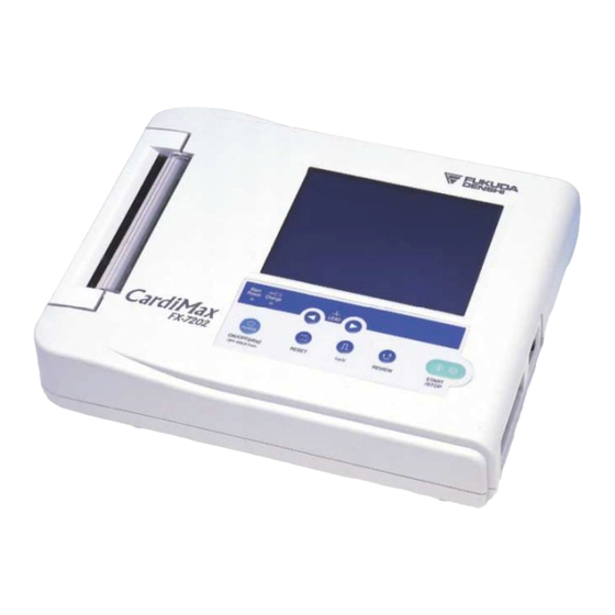
- Page 1 0086 CARDIMAX FX-7202 ELECTROCARDIOGRAPH Ver.04 OPERATION MANUAL • Before using this device, read this operation manual. • Store this manual in a location near the unit for future reference.
- Page 2 Copyright 2008 Fukuda Denshi Co., Ltd. No part of this document may be copied or transmitted in any form without the prior written permission of Fukuda Denshi Co., Ltd. Printed in Japan Note: Only qualified physicians or persons under instructions from physicians are allowed to use the FX-7202.
-
Page 3: How To Use The Operation Manual
Chapter 2, "Preparing the Cardimax FX-7202" provides you with a step-by-step procedure to set up the Cardimax FX-7202. This chapter also contains the procedure for charging the rechargeable battery. Chapter 3, "Operating the Cardimax FX-7202: Recording a Standard 12-lead ECG in the Automatic Recording Mode"... - Page 4 The step-by-step operation procedures in this manual are shown with screens and text. When you operate the Cardimax FX-7202, you use the Operation Panel keys and function keys of the Touch-panel. In this manual, the keys are indicated in the following manner.
-
Page 5: Special Notice To User
Special Notice to User Malfunction caused by EMC The Cardimax FX-7202 complies with the safety standards IEC60601-2-25 (1999) and IEC60601-1-2 (2001). However, if there is a strong electromagnetic wave nearby that exceeds the prescribed limit, the device could malfunction. If this happens, provide the required countermeasures. - Page 6 Equipment classification The Cardimax FX-7202 falls under the following equipment classifications: 1) Protection against electrical shock Class I, Internally powered 2) Type against electrical shock Applied part: Type CF 3) Protection against liquids entering the device General equipment standards 4) Operating safety in the presence of air-inflammable anesthetic gases or...
-
Page 7: Safety Precautions
Safety Precautions Before using the Cardimax FX-7202, be sure to read this section to ensure safety and • correct operation. Be sure to follow the precautions given below. These are important matters related to • safety. Safety notifications The following three safety notices alert the user to the level of hazard and damage that may result from not following the instructions or from misuse of the equipment. - Page 8 Precautions on analysis program CAUTION Interpretation and Minnesota codes given by the Cardimax FX-7202 do not instruct the physician as to the kind and degree of cardiac disease. Accordingly, four value judgments are given for electrocardiogram (ECG) waveform and although "abnormal"...
- Page 9 Nonexplosion proof DANGER Do not operate the FX-7202 in an environment where there is a risk of explosion. Do not operate the FX-7202 in the presence of flammable anesthetics. Magnetic resonance imaging WARNING Do not operate the FX-7202 during Magnetic Resonance Imaging (MRI) scanning.
- Page 10 Connection DANGER • This isolation measure is provided to protect the patient. Operation is bypassed if the electrodes on the patient cable come into contact with any other metal object or other electrically conductive objects, including the operator’s hands. When such contacts occur, there is a risk of electric shock, regardless of whether or not the objects are grounded.
- Page 11 Preventive maintenance CAUTION The purpose of preventive maintenance is to assure that the device is always in a safe operating condition and to prevent possible future problems. Preventive maintenance should be performed at least once during each 12-month period. Preventive maintenance consists of a thorough inspection of the device, all connections, and all attached cables for signs of physical damage.
- Page 12 Such damage to the equipment could cause an electric shock or fire. If you unintentionally drop the FX-7202, contact your local Fukuda Denshi sales and service representative. • Do not subject the liquid crystal display to a strong impact. The device can be damaged by unwarranted force.
- Page 13 Equipment Symbols ________________________________________________ The following symbols are printed on the Cardimax FX-7202. Attention: Read the Operation Manual. Type CF equipment Potential equalization terminal AC power supply LAN port...
- Page 14 Guidance for Electromagnetic Compatibility (EMC) ________________________ Details about the electromagnetic compatibility (EMC) of the Cardimax FX-7202 are given below. Before using the FX-7202, be sure to read and understand the following information. Compliance with electromagnetic emissions The Cardimax FX-7202 is intended for use in the electromagnetic environment specified in the following table.
- Page 15 Compliance with electromagnetic immunity 1 The Cardimax FX-7202 is intended for use in the electromagnetic environment specified in the following table. Before using the FX-7202, check the environment of the site where it is used. Immunity test IEC 60601 test...
- Page 16 Compliance with electromagnetic immunity 2 The Cardimax FX-7202 is intended for use in the electromagnetic environment specified in the following table. Before using the FX-7202, check the environment of the site where it is used. Immunity test IEC 60601 test...
- Page 17 Recommended separation distance between portable/mobile RF communications equipment and the FX-7202 The Cardimax FX-7202 is intended for use in an electromagnetic environment where RF emission interference is controlled. The electromagnetic interference can be prevented during operation by providing a minimum distance between portable/mobile RF communications equipment (transmitters) and the FX-7202 as recommended below (according to the maximum output power of the transmitter).
-
Page 19: Table Of Contents
Setting the Hospital Name ......................26 Setting the Language........................28 Using the Battery (Option) ......................30 Installing the Program Cartridge (Option) ..................33 Connecting the Cardimax FX-7202 to Optional Equipment............35 hapter 3. Operating the Cardimax FX-7202:Recording a Standard 12-lead ECG in the Automatic Recording Mode .......... 36 Connecting the Patient Cable to the Electrodes ................36... - Page 20 Reading ECG Data from the Built-in Memory................83 Deleting ECG Data ........................89 hapter 7. Setting Up Parameters of the Cardimax FX-7202 ......90 Overview of Parameters ......................90 General Flow of the Parameter Setup Procedure................98 Selecting the Number of Waveform Display Channels..............102 Selecting the Recording Format ....................103...
- Page 21 3. Additional Settings ..................164 Overview of Parameters ......................164 4. ECG Data ...................... 165 List of SCP-ECG Data Structures ....................165 Section Configurations.......................167 lossary ...................... 175 ndex ...................... 177...
-
Page 23: General Information
Configurations of The Cardimax FX-7202 _______________________________ The configuration of the Cardimax FX-7202 varies depending on whether or not the optional program cartridge PC-7403 is installed. When the PC-7403 program cartridge is installed, you can perform the optional functions of the Cardimax FX-7202. - Page 24 ECG waveforms, pulse rate, electrode condition, and analysis data on this screen. You can also enter alphabet letters and numerical values directly by touching the touch-panel display. See "Operation Panel” and “Touch-Panel Display" in Chapter 3, "Operating the Cardimax FX-7202" (pages 39 to 43).
- Page 25 General Information ECG data file management function The Cardimax FX-7202 allows you to save ECG data in the built-in memory. You can store a maximum 128 ECG data files in the built-in memory. See Chapter 6, "Managing ECG Data Files" (page 82).
-
Page 26: Names And Functions Of Parts
Chapter 1 Names and Functions of Parts Front view ________________________________________________________ (5) Thermal print head (1) Touch-panel display (4) Paper magazine (3) Magazine open button (2) Operation panel (1) Touch-panel display Displays ECG waveforms, patient information, and equipment status. Used also to enter patient data or perform various operations by touching the touch-panel keys (soft keys) provided on the screen. - Page 27 Provides the controls for the Cardimax FX-7202 operation. See "Operation Panel” and “Touch-Panel Display" in Chapter 3, "Operating the Cardimax FX-7202" (pages 39 to 43) for further information about the keys on the operation panel and touch-panel display. (3) Magazine open button Push to open the magazine cover.
- Page 28 Chapter 1 Side, rear, and bottom views _________________________________________ (6) LAN port (10 BASE T) (8) Potential equalization terminal (7) AC inlet (11) PATIENT connector (10) CARTRIDGE compartment (9) BATTERY PACK compartment...
- Page 29 General Information (6) LAN port (10 BASE T) Connect the LAN cable here for connection to a personal computer. (7) AC inlet Plug in the matching end of the power supply cord here. (8) Potential equalization terminal Connect the potential equalization cable (CE-12) to this terminal. CAUTION •...
-
Page 30: Accessories
Chapter 1 Accessories The common accessories of the FX-7202 required by all users are included in the same box as the main unit. The special accessories used under a different environment are provided in a separate box. There are three special accessory packages: (1) ASE-02G General Accessories Package, (2) ASE-02A Accessories Package for U.S. - Page 31 General Information ASE-02G General Accessories Package 1 Power supply cord CS-18(1 pc) 2 Power supply cord CS-20 (1 pc) 3 Patient cable CP-104J (1 pc) 4 Limb electrode TE-43 (1 set) 5 Chest electrode TE-01 (6 pc) 6 Keratin cream OJ-02 (1 pc) CAUTION •...
- Page 32 Chapter 1 ASE-02A Accessories Packages for U.S. 1 Power supply cord CS-24 (1 pc) 2 Patient cable CP-104L (1 pc) ASE-02E Accessories Package for Europe 1 Power supply cord CS-18 (1 pc) 2 Patient cable CP-104T (IEC) 3 Limb electrode TEE-43RG (1 pc) (1 set) 4 Chest electrode TEE-01RA...
-
Page 33: Optional Parts And Consumables
(page 1). Battery pack T8HRAAU-4713 Used as the power supply for the Cardimax FX-7202 in a remote location where there is no AC wall outlet. See "Using the Battery (Option)" in Chapter 2, "Preparing the Cardimax FX-7202"... - Page 34 Used as a ground cable. WARNING • Be sure to connect the optional potential equalization cable (CE-12) when using the Cardimax FX-7202 in a location where no hospital-grade 3-pin wall outlet is available. • When you use the Cardimax FX-7202 together with other equipment, perform potential equalization using the optional potential equalization cable (CE-12).
-
Page 35: Preparing The Cardimax Fx-7202
Chapter 2 Preparing the Cardimax FX-7202 This chapter will help you to choose an installation site, configure, and set-up the Cardimax FX-7202. Follow the instructions provided here to ensure that your electrocardiograph installation process is smooth and trouble-free. Be sure to provide a ground connection using the optional potential equalization cable (CE-12) if the FX-7202 is installed in a place where there are no hospital-grade 3-pin wall outlets. -
Page 36: Loading The Recording Paper
Chapter 2 Loading the Recording Paper Follow the steps below to load paper into the magazine. Z-fold paper OP-222TE Operation Press the paper magazine open button. The magazine cover will open slightly. Open the magazine cover. Lift up and completely swing open the magazine cover. - Page 37 Preparing the Cardimax FX-7202 The first page of the paper is placed on the exterior, and the remainder is inserted into the FX-7202. WARNING When the recording paper will be loaded, be careful about edge. Failure to do so may cause injury.
- Page 38 Chapter 2 Tear off the extended portion of paper. Tear off the extended portion of the paper on the paper cutter edge. Notes: Do not expose the recording paper to direct sunlight or leave it in a room with high •...
-
Page 39: Connecting The Power Supply Cord
AC inlet Power supply cord with 3-pin plug Hospital-grade wall output Additional information: The Cardimax FX-7202 can be operated on batteries when no AC wall outlets are available. See "Using the Battery (Option)" in this chapter (page 30). -
Page 40: Connecting The Ground
When hospital-grade 3-pin wall outlets are unavailable, be sure to connect one end of the optional potential equalization cable (CE-12) to the potential equalization terminal of the Cardimax FX-7202 and the opposite end to ground. (When the power supply cord is connected to a hospital-grade wall outlet, ground is provided automatically and therefore this procedure can be omitted.) -
Page 41: Connecting The Patient Cable
Connecting the Patient Cable Connect the mating end of the patient cable to the PATIENT connector on the right side of the Cardimax FX-7202. At this time, make sure the arrow mark on the cable plug is facing up. WARNING •... -
Page 42: Turning On Power
Chapter 2 Turning ON Power To turn ON the Cardimax FX-7202, use the [POWER ON/OFF (stby)] key on the Operation Panel of the Cardimax FX-7202. Before you turn ON the Cardimax FX- 7202, make sure that the power supply cord, potential equalization cable, and patient cable are connected properly. - Page 43 • When you use the battery as a power source, press [POWER ON/OFF (stby)] on the operation panel to turn the Cardimax FX-7202 ON and OFF. If you do not operate the unit for 5 minutes or more, power is turned OFF automatically to prevent unnecessary battery consumption.
-
Page 44: Adjusting The Display Contrast
Chapter 2 Adjusting the Display Contrast If the liquid crystal display (LCD) is not clearly visible, adjust the display contrast. Only STANDARD ECG MODE,ARRHTHMIA ECG MODE,and R-R TREND TEST MODE are effective. Operation Touch [ ] first and next, [CONTRAST]. The Contrast adjustment screen will appear. -
Page 45: Setting The Date Format And Built-In Clock
Setting the Date Format and Built-in Clock Set the date display format and built-in clock to record the accurate date and time. Operation Turn ON the Cardimax FX-7202. Touch [MENU] on the touch-panel display. The Mode select screen will appear. - Page 46 Chapter 2 Touch [Next ] to display the next page. Change the [Date Type] parameter if necessary. The date/time display format at the time of shipment is set to "MM-dd-yy". To change the date/time display format to "dd-MM-yy", touch the radio button of “dd-MM-yy”...
- Page 47 Preparing the Cardimax FX-7202 Enter the time. Use the number keys (0 to 9) on the touch-panel display to enter data. Use the left and right arrow keys to move the cursor. If the data you entered are incorrect, touch [AC] to clear all data or [DEL] to clear one digit.
-
Page 48: Setting The Hospital Name
Setting the Hospital Name Enter your hospital name. The hospital name you enter here will be printed on the reports. Operation Turn ON the Cardimax FX-7202. Touch [MENU] on the touch-panel display. The Mode select screen will appear. Touch [SET UP MODE]. - Page 49 Preparing the Cardimax FX-7202 Touch [NEXT ] to display the next page. Touch the down arrow key ([▼]) of the [Hospital] parameter on the left of the currently set name (if any). The HOSPITAL NAME keyboard will appear. This window has two pages,...
-
Page 50: Setting The Language
Chapter 2 Setting the Language The Cardimax FX-7202 supports five languages: English, German, French, Spanish, and Italian. The language is set to "English" at the time of shipment. Change the language if necessary. Operation Turn ON the Cardimax FX-7202. Touch [MENU] on the touch-panel display. - Page 51 Preparing the Cardimax FX-7202 Touch [ECG CONTROL]. The SET UP MODE (ECG CONTROL) screen will appear. Touch [Next ] to display the next page. Touch the down arrow key ([▼]) of the [Language] parameter on the left of the currently set language.
-
Page 52: Using The Battery (Option)
Chapter 2 Using the Battery (Option) If you install an optional battery pack (T8HRAAU-4713), you can operate the FX-7202 in a remote place where there is no AC power source. Battery power is automatically supplied when there is a power failure. When you use the batteries as a power source, unplug the power supply cord from the wall outlet. - Page 53 Preparing the Cardimax FX-7202 Installing the battery pack ____________________________________________ Operation Turn OFF the power and unplug the power supply cord. Press the [POWER ON/OFF (stby)] on the Operation Panel and unplug the power supply cord. Open the BATTERY PACK compartment cover.
- Page 54 • current occurs during charging, the Charge lamp will light amber. If the Charge lamp turns amber when you try recharging, contact your local Fukuda Denshi sales and service representative. The operating time of the battery with a one-time recharge varies widely depending •...
-
Page 55: Installing The Program Cartridge (Option)
• When plugging in or removing the program cartridge, be sure to turn OFF the Cardimax FX-7202. • Do not install a cartridge other than those specified for the Cardimax FX-7202. Operation Turn OFF the power and unplug the power supply cord. - Page 56 Chapter 2 Install the program cartridge. Gently push the program cartridge into the connector until it is seated securely. Reinstall the CARTRIDGE compartment cover removed in step 2. Insert the tab on the cover in place and close the PROGRAM CARTRIDGE compartment cover.
-
Page 57: Connecting The Cardimax Fx-7202 To Optional Equipment
Preparing the Cardimax FX-7202 Connecting the Cardimax FX-7202 to Optional Equipment When upgrading the software of the FX-7202, this port and a PC are connected. Operation Personal Computer_________________________________________________ WARNING • Before you connect your PC, unplug the power supply cord from the FX-7202. -
Page 58: Ecg In The Automatic Recording Mode
Chapter 3 Operating the Cardimax FX-7202: Recording a Standard 12-lead ECG in the Automatic Recording Mode This chapter describes the basic operation of the FX-7202 and the main aspects of ECG recording. Connecting the Patient Cable to the Electrodes Make sure the matching end of the patient cable is properly connected to the patient connector on the right side of the FX-7202. -
Page 59: Attaching The Electrodes To The Patient
Operating the Cardimax FX-7202: Recording a Standard 12-lead ECG in the Automatic Recording Mode Attaching Electrodes to the Patient Follow the instructions below to attach electrodes to the patient. Placing the electrodes in their proper locations is one of the most important factors for accurate ECG recording. - Page 60 Chapter 3 Attaching the chest electrodes (6 locations) Attach the chest electrodes in the following locations: Make sure the patient does not feel pain or discomfort. ① : The fourth intercostal space on the right sternal border. ② : The fourth intercostal space on the left sternal border. ③...
-
Page 61: Operation Panel
Operating the Cardimax FX-7202: Recording a Standard 12-lead ECG in the Automatic Recording Mode Operation Panel The functions of the operation panel keys and lamps are outlined below. (1) [POWER ON/OFF (stby)] key Press this key to switch the FX-7202 to power ON from standby status. Press this key for 2 seconds or more to switch the FX-7202 from power ON to standby status. - Page 62 The charge lamp lights in blue when the rechargeable battery is being charged. The charge lamp turns amber if any trouble such as abnormal battery temperature, battery voltage, or charge current occurs during charging. If the Charge lamp turns amber when you try recharging, contact your local Fukuda Denshi sales and service representative.
-
Page 63: Touch-Panel Display
Operating the Cardimax FX-7202: Recording a Standard 12-lead ECG in the Automatic Recording Mode Touch-Panel Display This screen displays patient information, equipment status, heart rate, function keys, various messages, and menus, in addition to the ECG waveform. You can also touch the areas or keys displayed on the screen to display a specific menu or perform a specific function. - Page 64 Chapter 3 (2) Equipment status icon display area You can check the current status of the electrodes attached to a patient, as well as the battery and recorder. • Warning icon for detached electrode This icon is displayed when an electrode becomes detached from a patient. •...
- Page 65 Operating the Cardimax FX-7202: Recording a Standard 12-lead ECG in the Automatic Recording Mode (7) Message area Messages such as an error message for detached electrodes or out of recording paper pops up here.
-
Page 66: Main Menus
Chapter 3 Main Menus The Cardimax FX-7202 has five operating modes: STANDARD ECG MODE, ARRHYTHMIA ECG MODE (PC-7403), R-R TREND TEST MODE, FILE MODE, and SET UP MODE. You can select the mode using the Mode select window. Outline of each operation mode STANDARD ECG MODE: Display, record, analyze (PC-7403 program cartridge), and measure the standard 12-lead ECG. -
Page 67: Entering Patient Data
Operating the Cardimax FX-7202: Recording a Standard 12-lead ECG in the Automatic Recording Mode Entering Patient Data You can enter data for each patient in the Standard ECG Mode, Arrhythmia ECG Mode (PC-7403 program cartridge), and R-R Trend Test Mode. The information you enter here will be displayed on the screen, printed on reports, and is used as reference for ECG analysis (PC-7403 program cartridge). - Page 68 MODE menu. See "Changing the Patient Data Parameters" in Chapter 7, "Setting Up Parameters of the Cardimax FX-7202" (page 118). Enter the patient's ID (maximum 16 digits). Touch [ID]. The ENTER THE ID keypad will appear. Touch the number keys ([0] to [9]) to enter the ID and touch [Enter].
- Page 69 Operating the Cardimax FX-7202: Recording a Standard 12-lead ECG in the Automatic Recording Mode Enter the patient's sex. The ENTER THE SEX window will appear. (Or, touch [SEX] to display the Enter the sex window.) Touch [Male] or [Female] to specify the patient's sex and touch [Enter].
- Page 70 The FX-7202 will calculate and display the age of a patient based on the birthday input. See "Changing the Patient Data Parameters" in Chapter 7, "Setting Up Parameters of the Cardimax FX-7202" (page 118). Enter the patient's name. The ENTER THE NAME keyboard will appear.
- Page 71 Operating the Cardimax FX-7202: Recording a Standard 12-lead ECG in the Automatic Recording Mode Enter the patient's ethnicity. The ENTER THE RACE window will appear. (Or, touch [Race] to display the ENTER THE RACE window.) Touch the ethnicity of a patient from the list displayed in the window and touch [Enter].
- Page 72 Chapter 3 Enter the patient's blood pressure. The ENTER THE BP keypad will appear. (Or, touch [BP] to display the ENTER THE BP keypad.) Touch the number keys ([0] to [9]) to enter the systolic and diastolic blood pressure (3 digits each, unit: mmHg) and touch [Enter].
- Page 73 Operating the Cardimax FX-7202: Recording a Standard 12-lead ECG in the Automatic Recording Mode the symptom (up to 12 characters) in the same manner as entering the patient’s name. See step 5 for keyboard operation of letters and numbers/symbols. If you have entered an incorrect number, touch [AC] to clear the data and then touch the correct number.
- Page 74 Chapter 3 Touch [Close] to end the patient's information input operation. The patient information you have just entered is saved in the memory and the previous screen reappears. To delete all values you have entered, touch [AC].
-
Page 75: Recording The Ecg
Operating the Cardimax FX-7202: Recording a Standard 12-lead ECG in the Automatic Recording Mode Recording the ECG After you finish the preparations described above, record the ECG. This section overviews the general ECG recording procedure using the Automatic Recording Mode as an example. - Page 76 Chapter 3 [MARK]: Prints a mark on the recording paper during ECG data printing. Displays the functions keys on the next page. Displays the function keys on the previous page. Additional information: When you turn ON the FX-7202, the Standard ECG Mode is selected. Select the Automatic Recording Mode.
- Page 77 Operating the Cardimax FX-7202: Recording a Standard 12-lead ECG in the Automatic Recording Mode Additional information: • To cancel the recording, press [START/STOP] again. • If you cannot record an accurate ECG, see "When You Cannot Record an Accurate ECG " in Chapter 8, "Maintenance and Troubleshooting" (page 132).
-
Page 78: Hapter 4. Recording The Electrocardiogram: Standard Ecg Mode
Recording the Electrocardiogram: Standard ECG Mode The Cardimax FX-7202 can be operated in three different function modes: Standard ECG Mode, Arrhythmia ECG Mode, and R-R Trend Test Mode. The Arrhythmia ECG Mode, however, is available only when the PC- 7403 program cartridge is installed. This chapter discusses how to record ECG in the Standard ECG Mode. - Page 79 Recording the Electrocardiogram: Standard ECG Mode Automatic Recording Mode (AUTO) Automatically changes the leads to be recorded, applies the calibrated 1mV waveform, and records the 12-lead ECG. Measurement recording Measures each waveform of the 12-lead ECG and prints the measurement results together with the ECG waveform.
-
Page 80: Automatic Recording Mode
You can change the number of display channels and recording channels as required. See "Selecting the Number of Waveform Display Channels" in Chapter 7, "Setting Up Parameters of the Cardimax FX-7202" (page 102). See "Selecting the Recording Format" in Chapter 7, "Setting Up Parameters of... - Page 81 See "Setting the filter ON/OFF" in “Additional information” in this chapter (page 61), and "Selecting the Filters" in Chapter 7, "Setting Up Parameters of the Cardimax FX-7202" (page 120). [COPY]: Starts reprinting the automatic recording ECG data, which was recorded immediately before pressing this key.
- Page 82 The printout starts and the tracings are printed in accordance with the preset format. When the recording is complete, it will stop automatically. See "Review Recording" in Chapter 5, "Recording the Electrocardiogram: Advanced Features" (page 67). See "STANDARD ECG MODE" in Chapter 7, "Setting Up Parameters of the Cardimax FX-7202" (page 94).
- Page 83 Recording the Electrocardiogram: Standard ECG Mode Additional information: • Automatic real-time recording samples the ECG data and records and measures/analyzes (PC-7403 program cartridge) the waveforms after [START/STOP] is pressed. Real-time recording starts sampling ECG data as soon as the P wave is detected. On the other hand, automatic review recording samples the ECG data and records and measures/analyzes (PC-7403 program cartridge) waveforms from those sampled 10 seconds prior to pressing [REVIEW].
-
Page 84: Manual Recording Mode
“6CH” is selected for the “Manual Recording CH.” parameter, six channels are always displayed regardless of the Display Channel parameter setting. See "Selecting the Number of Waveform Display Channels" in Chapter 7, "Setting Up Parameters of the Cardimax FX-7202" (page 102). - Page 85 See "Setting the filter ON/OFF" in “Additional information” in this chapter (page 64), and "Selecting the Filters" in Chapter 7, "Setting Up Parameters of the Cardimax FX-7202" (page 120). [MARK]: Prints a mark on recording paper during ECG data printing.
- Page 86 “Manual Recording CH.” parameter of the SET UP MODE (STANDARD ECG MODE) menu. See “STANDARD ECG MODE” in Chapter 7, "Setting Up Parameters of the Cardimax FX-7202" (page 94). • You can touch the ID area to enter patient data. You cannot enter patient data when the FX-7202 is performing a recording or displaying the function menu.
- Page 87 Recording the Electrocardiogram: Standard ECG Mode • The frequency characteristics of each filter are set using SET UP MODE (ECG CONTROL). When a filter is set to ON, the relevant filter icon ( “HF”, “MF”, “DF” ) will appear in the current status display area. See "Selecting the Filters"...
-
Page 88: Hapter 5. Recording The Electrocardiogram: Advanced Features
Recording the Electrocardiogram: Advanced Features The Cardimax FX-7202 can perform various examinations such as arrhythmia analysis and R-R trend test in addition to the standard 12-lead ECG recording. This chapter describes how to use these advanced features supported by the FX-7202. -
Page 89: Review Recording
Recording the Electrocardiogram: Advanced Features Standard ECG Mode, Review Recording Arrhythmia ECG Mode, R-R Trend Test Mode The Review Recording feature allows recording and measuring of 10 seconds of ECG that occurred prior to pressing [REVIEW] on the Operation Panel when you are performing a Standard ECG Mode (Automatic Recording), Arrhythmia ECG Mode, or R-R Trend Test Mode Recording. - Page 90 Chapter 5 Touch [STANDARD ECG MODE], [ARRHYTHMIA ECG MODE], or [R-R TREND TEST MODE]. Select the desired recording mode. Select the Automatic Recording Mode. If the [MANUAL] function key is displayed, touch [MANUAL] to select the Automatic Recording Mode. [AUTO] will be displayed.
-
Page 91: R-R Trend Test Mode
The recording format can be changed as required. See "R-R Trend Test Mode" of "Selecting the Recording Format" in Chapter 7, "Setting Up Parameters of the Cardimax FX-7202" (page 116). Additional information: In this mode, one channel that is selected by the R-R Trend Lead parameter of the... - Page 92 Chapter 5 Operation Display the Mode select window. Touch [MENU] to display the Mode select window. Note: The mode screen varies depending on the FX-7202 configuration. The mode screen shown is displayed when the PC-7403 program cartridge is installed. Touch [R-R TREND TEST MODE]. The R-R Trend Test Mode is selected.
- Page 93 Recording the Electrocardiogram: Advanced Features Select the measuring period. Touch [TARGET]. The TARGET SELECT window will appear. Select the measuring period from the following: 100BT, 200BT, 1 min, 2 min, 3 min, 4 min, 5 min. Touch [Close] to return to the previous screen.
- Page 94 If the Measured Value parameter of the SET UP MODE (R-R TREND TEST MODE) is set to ON, you can automatically print detailed measurement values. See "R-R Trend Test Mode" of "Selecting the Recording Format" in Chapter 7, "Setting Up Parameters of the Cardimax FX-7202" (page 116).
-
Page 95: Arrhythmia Ecg Mode
The recording format can be changed as required. See "Arrhythmia ECG Mode" of "Selecting the Recording Format" in Chapter 7, "Setting Up Parameters of the Cardimax FX-7202" (page 114). Additional information: In this mode, three channels selected by the Arrhythmia Lead 1CH, 2CH, and 3CH... - Page 96 Chapter 5 Operation Press the Mode select window. Touch [MENU] to display the Mode select window. Note: The mode screen varies depending on the FX-7202 configuration. The mode screen shown is displayed when the PC- 7403 program cartridge is installed. Touch [ARRHYTHMIA ECG MODE].
- Page 97 Recording the Electrocardiogram: Advanced Features Select the measuring period. Touch [TARGET]. The TARGET SELECT window will appear. Select the measuring period from the following: 1 min, 2 min, 3 min. Touch [Close] to return to the previous screen. Press [START/STOP] or [REVIEW] to start recording. When [START/STOP] is pressed, the FX-7202 starts sampling the waveforms of the three leads selected by the...
- Page 98 MODE) is set to ON, you can automatically print the detailed measurement values. See "Arrhythmia ECG Mode" of "Selecting the Recording Format" in Chapter 7, "Setting Up Parameters of the Cardimax FX-7202" (page 114). • If 121 or more arrhythmia values are detected, up to 118 waveforms are printed for the arrhythmia analysis report and the comment "Many irregular pulse were...
-
Page 99: Arrhythmia Automatic Extension Recording
Recording the Electrocardiogram: Advanced Features Arrhythmia Automatic Extension Recording Standard ECG Mode Automatically executes the arrhythmia analysis recording when a specific interpretation such as arrhythmia is detected during the 12-lead analysis recording. After performing analysis recording in the Standard ECG Mode, the Arrhythmia ECG Mode is executed automatically and the arrhythmia ECG report is printed. - Page 100 Additional information: See “Auto Mode Change” of the “Standard ECG Mode” in Chapter 7, "Setting Up Parameters of the Cardimax FX-7202" (page 94). Perform Analysis Recording in Standard ECG Mode. Additional information: See “Automatic Recording Mode” in Chapter 4, "Recording the Electrocardiogram: Standard ECG Mode"...
-
Page 101: Compressed Recording
Recording the Electrocardiogram: Advanced Features Compressed Recording Standard 12-lead waveform will be recorded with 5mm/s image. CAUTION The recorded data of compressed waveform will not be stored in the memory. Operation Touch [MENU]. MODE SELECT window will be displayed. Touch [COMPRESSED RECORDING]. COMPRESSED RECORDING MODE will be displayed. - Page 102 Chapter 5 The displayed function keys are as follows. [AUTO] or [**mm]: Selects the size of ECG waveform. (2.5, 5, 10, or 20 will be displayed for **.) [MENU]: Displays the MODE SELECT window. [FEED]: Feeds the recording paper. [FILTER]: Displays the filter setup window.
- Page 103 • The number of recording channels can be selected from “3ch” (default) or “6ch” for “Manual Recording CH” under SETUP MODE (STANDARD ECG MODE). See Chapter 7, "Setting Up Parameters of the Cardimax FX-7202: Standard ECG Mode". • Patient information can be entered by touching the ID area.
-
Page 104: Managing Ecg Data Files
This chapter provides information on how to read ECG data from the built-in memory. The Cardimax FX-7202 has a built-in memory for storing ECG data. The ECG data recorded by analysis and measurement are always saved in the built-in memory. The built-in memory can store a maximum of 128 ECG data files. -
Page 105: Reading Ecg Data From The Built-In Memory
Managing ECG Data Files Reading ECG Data from the Built-in Memory You can read ECG data from the built-in memory. Operation Display the Mode select window. Touch [MENU] to display the Mode select window. Touch [FILE MODE] The FILE MODE (ECG DATA READING) window appears. - Page 106 Chapter 6 Select the data to be read. Touch the data number of the data to be read. You can select two or more data. The selected data number is highlighted. If you select wrong data by mistake, touch the highlighted number again to cancel the selection of this data.
- Page 107 Managing ECG Data Files Searching ECG data________________________________________________ You can search for the ECG data to be read by ID number, date, last date, or name. Operation Perform steps 1 to 2 of “Reading ECG Data from the Built-in Memory.” Touch [SEARCH] on the FILE MODE (DATA READING) window.
- Page 108 Chapter 6 Search by date When you touch [Date], the DATE window appears. Touch the number keys ([0] to [9]) to enter the starting and ending test dates for a search. If you omit the starting date, the data preceding the ending date will be searched;...
- Page 109 Managing ECG Data Files CAUTION • A wildcard character “ ” can be used to search a name. By adding, “ ” at the end of the entered characters, a prefix search can be performed for the entered characters before “ ”. However, if any character is entered after the wildcard character “...
- Page 110 Chapter 6 Printing a list of ECG data ___________________________________________ You can print a list of the ECG data saved in the built-in memory. Operation Perform steps 1 to 2 of “Reading ECG Data from the Built-in Memory.” Touch [ ] to display the next page. Function keys on the next page will appear.
-
Page 111: Deleting Ecg Data
Managing ECG Data Files Deleting ECG Data The data stored in the memory can be deleted. CAUTION Once the data is deleted, it cannot be restored. Be cautious when performing the delete process. Operation Perform steps 1 to 2 of “Reading ECG Data from the Built-in Memory”. Select the data to be deleted. -
Page 112: Setting Up Parameters Of The Cardimax Fx-7202
Chapter 7 Setting Up Parameters of the Cardimax FX-7202 You can use the SET UP MODE menus to change the FX-7202 parameters such as the recording format and filters in order to meet the requirements of your ECG recording. Overview of Parameters The parameters you can change using the SET UP MODE are summarized in the table below. - Page 113 Setting Up Parameters of the Cardimax FX-7202 Parameter Setting Description QRS Beep ON, OFF* Set this parameter ON to have the unit sound beeps synchronized with heartbeat detection. Otherwise, set to OFF. Lead Off Buzzer ON, OFF* Set this parameter ON to...
- Page 114 Chapter 7 PATIENT DATA Parameter Setting Description Auto ID No. Inc ON, OFF* Set this parameter ON to assign patient IDs automatically. Each time an Automatic Recording during the REST status is completed successfully, the ID number is automatically incremented by 1. To assign each patient's ID manually, set this parameter OFF.
- Page 115 Setting Up Parameters of the Cardimax FX-7202 Parameter Setting Description Department ON*, OFF Set this parameter ON to include the patient's department information in the patient data. Otherwise, set to OFF. ∗: The settings marked with an asterisk (∗) are the default settings.
- Page 116 Chapter 7 STANDARD ECG MODE Parameter Setting Description Display Channel 3CH*, 6CH, 12CH Specify the number of channels of ECG waveforms to be displayed simultaneously on the same screen. You can select from: 3 channels, 6 channels, and 12 channels. This data can be specified for Automatic Recording.
- Page 117 Setting Up Parameters of the Cardimax FX-7202 Parameter Setting Description Report Format NONE*, DOM1, Specify the format of the analysis DOM3, COVER report or measurement report to be output during Analysis Recording (PC-7403) or Measurement Recording respectively. When this parameter is set to NONE, the analysis report or measurement report is not recorded.
- Page 118 Chapter 7 ARRHYTHMIA ECG MODE Parameter Setting Description Arrhythmia Lead 1ch I to V6 (II*) Specify the lead (1st channel) to be used for arrhythmia analysis. Arrhythmia Lead 2ch I to V6 (aVF*) Specify the lead (2nd channel) to be used for arrhythmia analysis. Arrhythmia Lead 3ch I to V6 (V5*) Specify the lead (3rd channel) to...
- Page 119 Setting Up Parameters of the Cardimax FX-7202 R-R TREND TEST MODE Parameter Setting Description R-R Trend Lead I to V6 (II*) Specify the lead to be used for R- R trend test. ECG Report NONE, Standard*, Set this parameter to select the...
-
Page 120: General Flow Of The Parameter Setup Procedure
Chapter 7 General Flow of the Parameter Setup Procedure The SET UP MODE screens consist of 7 menus: ECG CONTROL, PATIENT DATA, STANDARD ECG MODE, ARRHYTHMIA ECG MODE, R-R TREND TEST MODE, INITIALIZE, and MAINTENANCE. For further information about the operation of a specific parameter such as the recording format, see the following sections in this chapter. - Page 121 Setting Up Parameters of the Cardimax FX-7202 Select the desired SET UP MODE menu. Note that the ARRHYTHMIA ECG MODE menu is displayed only when the PC-7403 program cartridge is installed. Select the parameter to be changed. When the SET UP MODE screen displays a parameter to be changed, touch and select that parameter.
- Page 122 Chapter 7 Selecting the radio button You can turn on the radio button for selecting the desired value or item from two or more choices. Example: ● ] : Selected ○ ] : Not selected Changing the setting of an item with the down arrow (▼) button When there is a down arrow (▼) to the left of the current setting, touch this arrow.
- Page 123 Setting Up Parameters of the Cardimax FX-7202 Entering letters When there is a down arrow (▼) preceding the current setting, touch this arrow. If the setting requires an input of letters such as a hospital name, the alphanumeric keyboard window will pop up. Two keyboard pages are available: letters and symbols/number.
-
Page 124: Selecting The Number Of Waveform Display Channels
Chapter 7 Selecting the Number of Waveform Display Channels Use the following procedure to set the ECG waveform display format. Select the number of ECG waveform channels to be displayed simultaneously on the screen. Set the Display Channel parameter on the SET UP MODE (STANDARD ECG MODE) screen. -
Page 125: Selecting The Recording Format
Setting Up Parameters of the Cardimax FX-7202 Displays the lead groups for 6 channels on the screen. Each time you press LEAD [ ] or [ ], the lead group will be changed in the following order: I aV 12CH Displays the lead groups for 12 channels on the screen. - Page 126 Chapter 7 The following SET UP MODE screens are used to select the parameters related to the recording format of Measurement Recording: SET UP MODE (STANDARD ECG MODE) screen (page 1/2) Note: The mode screen varies depending on the FX-7202 configuration. The mode screen shown is displayed when the PC-7403 program cartridge is installed.
- Page 127 Setting Up Parameters of the Cardimax FX-7202 Measurement Wave: Select the extracting waveform. DOM: Sets the dominant waveform including the analyzing heartbeat as the extracting waveform. AVE: Sets the average waveform including the analyzing heartbeat as the extracting waveform. CAUTION If “3CH+R1”...
- Page 128 Chapter 7 ECG waveforms (6CH, COHERENT ALL)
- Page 129 Setting Up Parameters of the Cardimax FX-7202 Measurement report These are basic measurement values and measurement waveforms. You can select the following parameter: Report Format: Select the format of the measurement report to be printed. (NONE, DOM1, DOM3, or COVER) When this parameter is set to “NONE”, the measurement report is not recorded.
- Page 130 Chapter 7 Detailed measurement values These are detailed measurement values related to dominant waveforms used for Measurement Recording. Measured Value: Set this parameter “ON” to print the detailed measurement values. Otherwise, set to “OFF”. Detailed measurement values Standard ECG Mode - Analysis Recording _________________________ The analysis recording prints the following 4 types of data: ECG waveforms, analysis report, analysis comment, and detailed measurement values.
- Page 131 Setting Up Parameters of the Cardimax FX-7202 SET UP MODE (STANDARD ECG MODE) screen (page 2/2) ECG waveforms You can select the following parameters for the ECG waveforms to be used for Analysis Recording: Auto Recording CH.: Select the number of channels of the ECG waveform to be recorded simultaneously.
- Page 132 Chapter 7 ECG waveforms (3CH) ECG waveforms (3CH + rhythm lead) ECG waveforms (6CH, CONTINUOUS) ECG waveforms (6CH, COHERENT)
- Page 133 Setting Up Parameters of the Cardimax FX-7202 ECG waveforms (6CH, COHERENT ALL) Analysis report These are basic measurement values, interpretation, and analysis waveforms. The following parameter can be selected: Report Format: Select the format of the analysis report to be printed. (NONE, DOM1, DOM3, COVER) When this parameter is set to “NONE”, the...
- Page 134 Chapter 7 Analysis comment This is a comment for the interpretation, waveforms, and measured values. Comment: Set this parameter “ON” to print the comment. Otherwise, set to “OFF”. Analysis comment Detailed measurement values These are detailed measurement values related to dominant waveforms used for Analysis Recording.
- Page 135 Setting Up Parameters of the Cardimax FX-7202 Standard ECG Mode : _______________________________ Manual Recording Manual Recording prints the ECG waveform that is the same as the waveform on the screen. You can change the lead and sensitivity, reset the input waveform, and record a calibrated 1mV waveform during Manual Recording, as required.
- Page 136 Chapter 7 Arrhythmia ECG Mode ________________________________________ The arrhythmia analysis prints the arrhythmia ECG report and measured values. Select the report format for the arrhythmia ECG report and measured values. The SET UP MODE (ARRHYTHMIA ECG MODE) screen is used to set the parameter related to the recording format of the Arrhythmia ECG Mode.
- Page 137 Setting Up Parameters of the Cardimax FX-7202 Arrhythmia analysis (arrhythmia ECG report) Arrhythmia analysis (analysis report) Arrhythmia analysis (measured values)
- Page 138 Chapter 7 R-R Trend Test Mode _______________________________________________ The R-R trend test will print the test report together with ECG waveforms, and measured values. Select the report format for these reports. The SET UP MODE (R-R TREND TEST MODE) screen is used to set the parameters related to the recording format of the R-R Trend Test Mode.
- Page 139 Setting Up Parameters of the Cardimax FX-7202 R-R trend test (ECG test report) R-R trend test (analysis report) R-R trend test (measured values)
-
Page 140: Changing The Patient Data Parameters
Chapter 7 Changing the Patient Data Parameters Add or delete items to be entered as patient data. To change the patient data parameters, use the SET UP MODE (PATIENT DATA) screen (page 1 and page 2). SET UP MODE (PATIENT DATA) screen (... - Page 141 Setting Up Parameters of the Cardimax FX-7202 Race: Set this parameter to include the patient's ethnicity in the patient data. Otherwise, set to “OFF”. Height: Set this parameter to “cm” or “inch” to include the patient's height in the patient data. Otherwise, set to “OFF”.
-
Page 142: Selecting The Filters
Chapter 7 Selecting the Filters Set the cut-off frequency of the hum filter (HF), muscle filter (MF), drift filter (DF), and high-cut filter. Once the filter parameters are set, they can be turned ON and OFF by simply touching [FILTER] during sampling. SET UP MODE (ECG CONTROL) screen (1/2) Select the following parameters: Hum Filter:... -
Page 143: Initializing Parameters
Setting Up Parameters of the Cardimax FX-7202 Initializing Parameters You can reset the parameters to their default settings (excluding date and time setting). Operation Display the Mode select window. Touch [MENU] to display the Mode select window. Touch [SET UP MODE]. - Page 144 Chapter 7 Touch [Enter]. The parameters are reset to their default settings. To cancel the initialization operation, touch [Cancel].
-
Page 145: Maintenance And Troubleshooting
Chapter 8 Maintenance and Troubleshooting Performing the Self-diagnostics Test The FX-7202 provides the following five types of user menus for the daily machine check. • TEST PATTERN Menu for selecting the built-in ECG test pattern waveform used for operation checks and demonstration. •... - Page 146 Chapter 8 Touch [SET UP MODE]. The SET UP MODE (MENU) window will appear. Touch [MAINTENANCE]. The SET UP MODE (MAINTENANCE) window will appear. See the corresponding section for the detailed operation of each test. Note: You cannot access the MAKER MAINTENANCE menu. The manufacturer uses it for checks and adjustment of this machine during the manufacturing process and product inspection.
- Page 147 Maintenance and Troubleshooting Operation Open the SET UP MODE (MAINTENANCE) window. Perform steps 1 to 3 of "Starting the test menu" (pages 123 to 124) to open the SET UP MODE (MAINTENANCE) window. Touch [TEST PATTERN]. The MAINTENANCE (TEST PATTERN) window will appear.
- Page 148 Chapter 8 Notes: • "NORMAL" or "PVC WAVE" will appear respectively during the recording if you select NORMAL or PVC WAVE. • The detached electrode information is ignored if you select “NORMAL” or “PVC WAVE”. • Always “NONE” is selected at the time of power-on and initialization. The test pattern information is not saved.
- Page 149 Maintenance and Troubleshooting Press [START/STOP] key. When all recording tests are complete (the recording test in 50mm/second is finished), the MAINTENANCE (RECORDING TEST) window reappears. Notes: • You can end the recording test by pressing [START/STOP]. The MAINTENANCE (RECORDING TEST) window reappears. •...
- Page 150 Chapter 8 Press a key on the operation panel and make sure that the corresponding key is highlighted on the screen. For example, press [START/STOP]. The [START STOP] indication on the screen will be highlighted. After you finish the test, touch [MENU]. The SET UP MODE (MAINTENANCE) window will reappear.
- Page 151 Maintenance and Troubleshooting Performing the buzzer test ___________________________________________ Use the following procedure to run the BUZZER TEST menu. Operation Open the SET UP MODE (MAINTENANCE) window. Perform steps 1 to 3 of "Starting the test menu" (pages 123 to 124) to open the SET UP MODE (MAINTENANCE) window Touch [BUZZER TEST].
-
Page 152: Cardimax Fx-7202 Maintenance
Periodic checks of medical electronic equipment are indispensable for prevention of faults and accidents and for the maintenance of safety and performance. For more information, contact your local Fukuda Denshi service representative. If any item in Appendix C, "Periodic Check Lists" (page 140) fails, the overall judgment is also "failed."... - Page 153 Maintenance and Troubleshooting Cleaning and disinfecting ____________________________________________ CAUTION Do not heat sterilize with water, steam, or air. Electrodes (clips, cups, plates): Use the following procedures for the electrodes. Cleaning: Use a cloth moistened with a household cleaning agent and wipe the entire electrode. Next, wipe with a new cloth that is moistened with ordinary touch water and let the electrodes dry.
-
Page 154: When You Cannot Record An Accurate Ecg
Chapter 8 When You cannot Record an Accurate ECG If accurate ECG samples cannot be obtained, check the following items and retry the operation: 1. Are the examination conditions appropriate? • Make sure the FX-7202 is not used near devices that cause noise, such as X-ray units, ultrasonic equipment, cellular phone, or other electrical appliances. -
Page 155: When An Error Message Is Displayed
Maintenance and Troubleshooting 5. Is the patient's condition satisfactory? • Make sure the patient is comfortable. If the patient is tense, reassure him or her that the ECG examination is simple and harmless. • Make sure the patient does not move or speak during the examination. •... - Page 156 Chapter 8 Error messages related to the magazine and recording paper _______________ MAGAZINE UP Cause: The paper magazine is open. Action to be taken: Make sure the magazine cover is closed properly. See "Loading the Recording Paper" (pages 14 to 16). NO PAPER Cause: The paper magazine has run out of recording paper.
- Page 157 The thermal recording head is overheated. Action to be taken: Turn OFF the FX-7202 immediately. This is assumed as a machine failure. Contact your local Fukuda Denshi sales and service representative and ask for repairs. ECG AMP ERROR! Cause: ECG amplifier control failure.
-
Page 158: Appendix A. Specifications
Appendix A. Specifications Electrocardiograph Leads: Standard 12 leads Sensitivity: 1/4, 1/2, 1, 2cm/mV, or automatic ±550mV or greater Polarization voltage: Frequency response: 0.05 to 150Hz Time constant: 3.2 sec. Common mode rejection: 2mmp-p or lower (103dB or more) Input impedance: 50M ohms or greater Input circuit current: 5x10... - Page 159 Appendix A Display Type: Liquid crystal display (LCD) with backlighting Resolution: 320 dot (horizontal) x 240 dot (vertical) Patient data: ID number, age, sex, height, weight, etc. Measurement operation Basic measurement value: Heart rate, R-R time, P-R time, QRS time, QT time, QTc, electrical axis, SV1, RV5(6) Heart Rate measurement: 20 to 300 BPM ±2 BPM...
- Page 160 Appendix A Storage environment Temperature: -10 to +55 degrees Celsius (14 to 131 degrees Fahrenheit) Humidity: 10 to 95% (no condensation) Atmospheric pressure: 70 to 106kPa (700 to 1060mbar)
-
Page 161: Appendix B. Daily Check List
The power supply cord and patient cable cord and patient cable are patient cable must be connected firmly to the connected firmly to the Cardimax FX-7202. Cardimax FX-7202. 2. Limb electrode, chest Make sure the limb The limb electrodes and electrode... -
Page 162: Appendix C. Periodic Check List
The power supply cord and patient cable cord and patient cable are patient cable must be connected firmly to the connected firmly to the Cardimax FX-7202. Cardimax FX-7202. 2. Limb electrode, chest Make sure the limb The limb electrodes and electrode... - Page 163 Periodic Check List Type of check Check item Procedure Criterion Self- Performance 1. Recording speed Execute the RECORDING The RECORDING TEST diagnostics TEST (MAINTENANCE results must show a normal test menu) to make sure the paper feed condition. paper feed condition is normal.
-
Page 164: A Ppendix D. Lan Communication Function
Appendix D. LAN communication function 1. Setting the Network Connection This chapter provides an explanation of the procedure for configuration parameters for transmitting ECG data. The network-based filing function provided by the FX-7202 uses the FTP protocol. Since the FX-7202 operates as an FTP client, a personal computer (PC) is required that is provided with an FTP server function when connected to the network. -
Page 165: Initial Network Setup
LAN communication function Initial Network Setup This section provides an explanation of the reference procedure for connecting the FX-7202 to a network using a PC at the facility where the FX-7202 is installed. Notes: The setup procedure described below provides an example of setting up operation •... - Page 166 Appendix D. Display [Internet Protocol (TCP/IP) Properties]. Click on [Properties (P)] of the [Local Area Connection Status] window to display the [Local Area Connection Properties] window, and then click on [Properties (R)] after having selected the [Internet Protocol (TCP/IP)] list. Set the IP Address.
- Page 167 LAN communication function TCP/IP Setup (Windows XP) Open the Control Panel. Click the [Start] button located in the lower left corner of the screen, and then open the Control Panel from the [Setup] menu. Display the [Local Area Connection Status] window. Double-click on the [Network Connections] icon of the control panel to display the [Network Connections]...
- Page 168 Appendix D. Set the IP Address. Select the [Use the following IP address] radio button, enter [192.168.2.127] for the IP address and [255.255.255.0] for the subnet mask, and then click the [OK] button. Similarly, click the [OK] button of the [Local Area Connection Properties] window as well as the [Close (C)] button of the [Local Area Connection Status] window to close each window.
- Page 169 LAN communication function Network Connection Setup This section provides an explanation of the procedure for setting up the FTP server connection using Internet Service Manager (IIS). Please refer to the other procedure if you do not use IIS. Notes: The following procedure is to be performed by a user that has an administrator •...
- Page 170 Appendix D. Select the FTP server. Click on the [Details] button after having selected Internet Information Service (IIS) to display the [Internet Information Service (IIS)] window of the Internet Information Service (IIS), check the check box of the File Transfer Protocol (FTP) server, and then click the [OK] button to close the window.
- Page 171 LAN communication function Setting Up the FTP Server (Windows 2000) Open the Control Panel. Click the [Start] button located in the lower left corner of the screen, and then open the Control Panel from the [Setup] menu. Display the [Administrative Tools] window. Double-click on the [Administrative Tools] icon of the control panel to display the [Administrative Tools] window.
- Page 172 Appendix D. Display [Internet Information Service]. Double-click on the [Internet Service Manager] icon of the [Administrative Tools] window to display the [Internet Information Service] window. Then expand the icon of the computer displayed to the left to display the [Default FTP Site].
- Page 173 LAN communication function Installing the FTP Server (Windows XP) Open the Control Panel. Click the [Start] button located in the lower left corner of the screen, and then open the Control Panel from the [Setup] menu. Display the [Windows Component Wizard]. Double-click on the [Add/Remove Programs] icon of the control panel to display the [Add/Remove Programs]...
- Page 174 Appendix D. Setting Up the FTP Server (Windows XP) Open the Control Panel. Click the [Start] button located in the lower left corner of the screen, and then open the Control Panel from the [Setup] menu. Display the [Administrative Tools] window. Double-click on the [Administrative Tools] icon of the control panel to display the [Administrative Tools]...
- Page 175 LAN communication function Set the security account. Right-click on [Default FTP Site] and select Properties to display the [FTP Site Properties] window, and then select the [Security Account] tab. Remove the [Allow Anonymous Connections] check box. Set the home directory. Select the [Home Directory] tab of the [FTP Site Properties] window.
- Page 176 PC. The Cardimax FX-7202 has built-in memory for storing ECG data. The ECG data recorded by analysis and measurement are saved in the built-in memory. The built-in memory can store a maximum of 128 ECG data files.
-
Page 177: Managing Ecg Data Files
LAN communication function Reading ECG Data from the Built-in Memory ECG data can be read from the built-in memory. Operation Display the Mode select window. Touch [MENU] to display the Mode select window. Touch [FILE MODE]. The FILE MODE (MENU) window appears. Touch [ECG DATA READING] The FILE MODE (ECG DATA READING) window appears. -
Page 178: Reading Ecg Data From The Built-In Memory
Appendix D. Select the data to be read. Select the data number of the data to be read. You can select two or more data. The selected data number is highlighted. If you select a data number in error, touch the highlighted number again to cancel the selection. - Page 179 LAN communication function Searching ECG data _______________________________________________ You can search for the ECG data to be read by ID number, date, or last date. Operation Perform steps 1 to 3 of “Reading ECG Data from the Built-in Memory.” Select [SEARCH] on the FILE MODE (DATA READING) window.
- Page 180 Appendix D. Search by date When you select [Date], the DATE window appears. Press the number keys ([0] to [9]) to enter the starting and ending test dates for a search. If you omit the starting date, the data preceding the ending date will be searched;...
- Page 181 LAN communication function Printing a list of ECG data __________________________________________ You can print a list of the ECG data saved in the built-in memory. Operation Perform steps 1 to 3 of “Reading ECG Data from the Built-in Memory.” Touch [ ] to display the next page.
- Page 182 Appendix D. Transmitting ECG Data to a PC ECG data stored in the memory of the FX-7202 can be transmitted to a PC. In addition, this data can be transmitted automatically. When you select data transmission to a PC via a LAN, you can choose either SCP-ECG or Fukuda Original as the data format.
-
Page 183: Transmitting Ecg Data To A Pc
LAN communication function Select [SEND] to transmit the ECG data to the PC. ECG data is transmitted to the PC when [SEND] is touched. During transmission, the [ECG DATA SENDING] message is displayed. Notes: The same ECG data may be transmitted as many times as desired. •... - Page 184 Appendix D. Transmitting ECG Data Stored in Memory to a PC ______________________ ECG data stored in memory of the FX-7202 can be selected from a record list and then transmitted to a PC. Operation Perform steps 1 to 3 of “Transmitting ECG Data to a PC.” Display the ECG DATA TRANSMITTING window of the FILE MODE.
- Page 185 LAN communication function 3. Additional Settings This chapter provides an explanation of additional settings. Refer to Chapter 7 of the FX-7202 Operation Manual for information on other settings and operating procedures. Overview of Parameters FILE MODEL Parameter Setting Description Auto Sending ON, OFF* Automatically transmits result data to a PC after...
-
Page 186: Additional Settings
Appendix D. 4. ECG Data The following provides an explanation of the ECG data sent as a reply from the FX-7202 to the PC. Data can be output in either Fukuda Original format or SCP-ECG (Standard Communications Protocol for Computer-Assisted Electrocardiography) format. Use Set Up mode to select the format. Data in Fukuda Original format can only be viewed on a PC with EFS-200 installed. -
Page 187: Ecg Data
LAN communication function Section 8 Textual diagnosis from the “INTERPRETIVE” device Section 10 Lead measurement results Data Structures of R-R Trend Test Mode Record Header Checksum CCITT over the entire record Record Header Size of the entire ECG record (in bytes) Section 0 Pointers to data areas in the record... - Page 188 Appendix D. Section Configurations This section provides an explanation of the data of each section set with the FX-7202. Explanations are omitted for those sections for which data has already been set by SCP-ECG. Section 0 This section contains data that has already been set by SCP-ECG. Section 1 This section contains data that already been set by SCP-ECG.
-
Page 189: Section Configurations
LAN communication function Affiliation FX-7202 original data Avg. blood pressure FX-7202 original data Medication information 2 FX-7202 original data Subjective symptoms FX-7202 original data FX-7202 original data Presentation FX-7202 original data Respiration rate FX-7202 original data Load category FX-7202 original data Load information FX-7202 original data Terminal no. - Page 190 Appendix D. Presentation (binary) Respiration rate (binary) Load category (binary) Load information (binary) Byte Contents Type of load device Elapsed time (hours) Elapsed time (minutes) Elapsed time (seconds) 9-10 Protocol 11-12 Stage no. 13-14 Stage time (minutes) 15-16 Stage time (seconds) 17-18 Watts 19-20...
- Page 191 LAN communication function Order no. (Text Characters) Byte Contents 1-128 Order no. 1 129-256 Order no. 2 Arbitrary Comments (Text Characters) Section 3 This section contains data that has already been set by SCP-ECG. Section 6 This section contains data that has already been set by SCP-ECG. Furthermore, waveform data is set in the manner shown below.
- Page 192 Appendix D. Notch (binary) Noise level (binary) Defective recording information (binary) Trigger point (binary) P wave beginning point (binary) P wave ending point (binary) QRS wave beginning point (binary) QRS wave ending point (binary) T wave beginning point (binary) T wave ending point (binary) Next R-R (binary) Pre-compensation value (binary) Post-compensation value (binary)
- Page 193 LAN communication function Average R-R time (binary) Average R-R time is set with coded 2-byte data. Maximum R-R time (binary) Maximum R-R time is set with coded 2-byte data. Minimum R-R time (binary) Minimum R-R time is set with coded 2-byte data. Maximum/minimum R-R time (binary) The ratio of maximum R-R time to minimum R-R time is set with coded 2-byte data.
- Page 194 Appendix D. R-R Histogram Data LENGTH VALUE (Parameter data) Data for R-R interval of less than 30 seconds (binary) Byte Contents No. of data records Ratio (units: %) Data for R-R interval of 0.30 to less than 0.31 seconds (binary) Byte Contents No.
- Page 195 LAN communication function LENGTH VALUE (Parameter data) Parameter length (binary) The size of the data set for R wave position information is set with coded 2-byte data. 4 x No. of R wave position (binary) R waves R wave position from the start of testing is set in msec units in the order of detection with non-coded 4-byte data.
- Page 196 Appendix D. BIT 7 BIT 6 BIT 5 BIT 4 BIT 3 BIT 2 BIT 1 BIT 0 1st beat 2nd beat 3rd beat 4th beat 5th beat 6th beat 7th beat 8th beat 1st byte 2nd byte Nth byte Beats 1-8 Beats 9-16 Beats n-7 to n...
-
Page 197: Glossary
Glossary Backup battery: A Lithium battery used for retaining clock data. For replacement, contact your local Fukuda Denshi service representative. Coefficient of variation (CV): The R-R Trend Test Mode measures the R-R interval of the sampled ECG waveform and calculates the coefficient of variation using the following formula: Standard deviation ×... - Page 198 Glossary Histogram: Displayed on the R-R trend test result report. The measured R-R interval is indicated on the horizontal axis and its frequency is indicated as a percentage on the vertical axis. A histogram picks up only the normal beat from all the R-R intervals measured, and represents these normal beats in a graph.
-
Page 199: Index
Index CONTRAST AC inlet 6, 7, 17 conventions AC power supply 20, 21 age (AGE) 41, 45, 47, 48 cut-off frequency 90, 120 20, 21 analysis comment daily checks 130, 139 analysis recording 1, 56, 57, 108 date format analysis report 111, 114, 116 setting the date format 23 to 25... - Page 200 Index Main Power lamp 20, 21, 32, 39, 40 Manual Recording Mode (MANUAL) File Mode 44, 83 1, 56, 57, 62 to 65, 113 filter 53, 59, 63, 70, 74, 175 measurement recording 1, 56, 57, 103 setting the filter ON/OFF 61, 64, 71, 75 measurement report selecting filters...
- Page 201 Index race (RACE) 45, 49 thermal print head 4, 5 radio button 99, 100 touch-panel display 4, 41 to 43 adjusting the display contrast rechargeable battery See battery. transitional zone recording format 103 to 117 Arrhythmia ECG Mode 114 to 115 trend graph Standard ECG Mode (analysis recording) 108 to 112...
- Page 202 Index PATIENT DATA Auto ID No. Inc 92, 118 Blood Pressure 92, 119 Comment 92, 119 Department 93, 119 Drug 92, 119 Fixed ID Number 92, 118 Height 92, 119 Input Birthday 48, 92, 118 Name 92, 118 Race 92, 119 Symptoms 92, 119 Ward...
- Page 204 39-4, Hongo 3-chome, Bunkyo-ku, Tokyo, Japan Phone:+81-3-3815-2121 Fax:+81-3-3814-1222 4L002987E 200810...
Need help?
Do you have a question about the CARDIMAX FX-7202 and is the answer not in the manual?
Questions and answers