Fukuda Denshi DynaScope 7000 Series Operation Manual
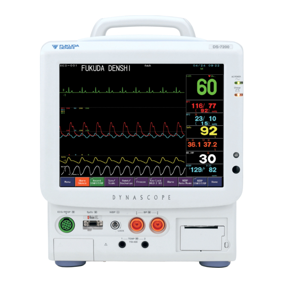
Bedside monitor
Hide thumbs
Also See for DynaScope 7000 Series:
- Operation manual (475 pages) ,
- Service manual (143 pages)

Subscribe to Our Youtube Channel
Related Manuals for Fukuda Denshi DynaScope 7000 Series


Summary of Contents for Fukuda Denshi DynaScope 7000 Series
- Page 1 DynaScope 7000 Series Bedside Monitor DS-7200 System Ver.08 Operation Manual 《 Maintenance 》 ...
- Page 2 • The company and product names used in this manual are trademarks or registered trademarks. • If this manual has pages missing or out of order, contact Fukuda Denshi for replacement. • Only physician or persons instructed by physicians are allowed to use the equipment.
-
Page 3: Table Of Contents
Preface Thank you for purchasing this product. Before using this product, read the following precautions to make sure the product is used correctly and safely. Composition of This Operation Manual························· ii Safety Precautions ························································· iii Labels Attached to the Unit ··········································iii Measurement Unit for Each Parameter·······················... -
Page 4: Composition Of This Operation Manual
Composition of This Operation Manual The DS-7200 System Operation Manual is composed of the following 3 sections. ≪General Description≫ This section is composed of the chapters stating the general description of the device and basic operation procedure. 1. General Description Describes the outline of this equipment. -
Page 5: Safety Precautions
Safety Precautions Read the “Safety Precautions” thoroughly before use to ensure correct and safe use of the product. Be sure to follow the precautions indicated below, as these are important messages related to safety. Failure to follow this message may cause immediate threat of death or serious D A N G E R injury, or complete failure of the equipment. - Page 6 DS-7200 System DANGER Risk of explosion if used in the presence of flammable anesthetics. CAUTION Before connecting, read instruction manual. CAUTION To reduce the risk of electric shock, do not remove the cover. Refer servicing to qualified service personnel. DANGER •...
- Page 7 HU-71/HU-72/HU-73 Option Unit DANGER Risk of explosion if used in the presence of flammable anesthetics. CAUTION Before connecting, read instruction manual. CAUTION To reduce the risk of electric shock, do not remove the cover. Refer servicing to qualified service personnel. <HU-71>...
- Page 8 Measurement Unit for Each Parameter The measurement units for this equipment are as follows. Detail Parameter Display Unit Default Invasive Blood Pressure PR_IBP Heart Rate / Pulse PR_SpO Rate Non-Invasive Blood PR_NIBP Pressure ST Level mm, mv Impedance Respiration RR_IMP Respiration Rate RR_CO Ventilator...
- Page 9 Detail Parameter Display Unit Default Spontaneous Spontaneous Respiration S_RR Respiration Peak End Expiratory Peak End Expiratory PEEP Pressure Pressure Fraction of Fraction of Inspiratory Inspiratory Oxygen Oxygen Mixed Venous Oxygen Saturation Central Venous Oxygen ScvO Saturation Arterial Oxygen Saturation Oxygen Uptake Index Oxygen Transport mL/minute Oxygen Consumption...
-
Page 10: Graphic Symbols
Graphic Symbols Refer following for the meaning of the symbols indicated on the equipment. Symbols indicated on the equipment Symbol Description Caution; refer to accompanying documents Indicates the need to refer to related accompanying documents before operation. Equipotential Terminal Indicates the terminal to equalize the potential difference when interconnecting the devices. - Page 11 Symbol Description Signal Input Part Manufactured Date TCP/IP Network Connector Connects to TCP/IP network. RS-232C Connector Connects the related device. Eject Indicates the switch to remove the recorder paper cassette.
- Page 12 Symbols displayed on the screen Symbol Description Battery Mark During battery operation, battery status will be displayed. Alarm OFF Indicates the alarm is OFF. Heart Rate Synchronization Mark This mark flashes synchronizing to the heartbeat. Respiration Synchronization Mark This mark flashes synchronizing to the inspiration. Event Key This mark will be displayed when an alarm generates.
-
Page 13: Precautions For Safe Operation Of Medical Electrical
Keep the unit clean to ensure proper operation of the next use. If the equipment is damaged and in need of repair, user should not attempt service. Label the unit “OUT OF ORDER” and contact Fukuda Denshi. Do not remodel the equipment. -
Page 14: Precautions For Safe Operation Of Medical Telemetry·xii
When interference or breakdown occurs in telemetry communication, the user is required to inform the zone manager and the overall manager of the problems. The zone manager and overall manager are to deal with the problem properly and/or contact their nearest Fukuda Denshi representative for service. -
Page 15: Precautions About The Maintenance
Maintenance, Modifications, and Repairs Fukuda Denshi is liable for the safety, reliability, and performance of its equipment only if; Maintenance, modifications, and repairs are carried out by authorized personnel. Components are used in accordance with Fukuda Denshi operating instructions. -
Page 16: Non-Explosion Proof
Non-Explosion Proof Never operate the equipment in the presence of flammable anesthetics, high concentration of oxygen, or inside hyperbaric chamber. Also, do not operate D A N G E R the equipment in an environment in which there is a risk of explosion. Explosion or fire may result. -
Page 17: Precautions About Magnetic Resonance Imaging
Fukuda Denshi. It is the user’s responsibility to contact Fukuda Denshi to determine the compatibility and warranty status of any connection made to another manufacturer’s equipment. -
Page 18: Precautions About The Ds-7200 System
The DS-7200 system is not intended for use during patient transport outside a healthcare facility, and is not considered as mobile equipment. Do not connect unit or cable not authorized by Fukuda Denshi to any I/O connector. If done so by mistake, the DS-7200 system cannot deliver its maximum performance and the connected units may be damaged, resulting in a safety hazard. - Page 19 “Oridion Medical 1987 Ltd.”. Refer to “12. Optional Accessories”, for list ® of specified “Oridion Medical 1987 Ltd.” FilterLine sampling products. These accessories may be purchased from Fukuda Denshi or any authorized “Oridion Medical 1987 Ltd.” distributor. When monitoring CO (MGU-721/MGU-722), always consider the circumference of the intubation tube when using the airway adapter.
- Page 20 HUB for the TCP/IP network. We cannot assure proper operation if used improperly. Use a 10M repeater HUB recommended by Fukuda Denshi for the DS-LAN ΙΙ network. If a 100M HUB or a switching HUB is used, a communication error may occur.
- Page 21 Systems This equipment is intended to be used for only one patient. The installation of this equipment and its option unit should be performed by our service representative or a person who is well acquainted with this equipment. The internal switch setting will be performed by our service representative.
- Page 22 The indication for continuous use of the electrode is about one day. Replace the electrode if the skin contact gets loose due to perspiration, etc. When an electrode is attached to the same location for a long period, some patients may develop skin irritation. Check the patient’s skin condition periodically and change the electrode site as required.
- Page 23 Monitoring If the nail is rough, dirty, or manicured, accurate measurement will not be possible. Change the finger or clean the nail before attaching the probe and sensor. The Dyna Alert estimates the change in circulatory dynamics from the photoplethysmogram (SpO ) of the finger.
- Page 24 ® For Masimo sensor, change the sensor attachment site every 4 hours for the reusable sensor, and every 8 hours for the disposable sensor. Exercise extreme caution with poorly perfused patients; skin erosion and pressure necrosis can be caused when the sensor is not frequently moved.
- Page 25 When a PTG (SpO ) sensor is applied to the toe or forehead, the Dyna Alert may not function depending on the patient’s condition. When using the Dyna Alert function, be aware of these risks and do not increase the NIBP interval time by relying only on the Dyna Alert function.
- Page 26 Note that the Systolic Pressure (SYS) = Peak Systolic Pressure (PSP) for the graphic trend, data base, and alarm setup. When ECG is not measured, PDP cannot be calculated. The undisplayed BP data (SYS/DIA/Mean) will not generate a BP alarm or be displayed in the tabular trend.
- Page 27 Regardless of ON/OFF setting of “Suspend Arrhy. Analysis during Interference” under Hospital Setup (Preset Menu), the “Cannot analyze" alarm will generate when analysis is suspended for more than 30 seconds. The measurement range and alarm range differs for the following parameters.
- Page 28 ST Measurement For the lead which the electrode is detached, the reference waveform setup cannot be performed. Check if the electrode is correctly attached, and perform the setup again. CF Card Use only the specified CF card. Use only the CF card formatted with this device. Restart the system after reading the setup data from the CF card.
-
Page 29: Precautions About The Wired Network System
Precautions about the Wired Network System (DS-LAN ΙΙ/DS-LANIII) Do not connect unspecified device to a wired network. Do not mix devices with DS-LANII and DS-LANIII setting in the same wired network. The network may cease and proper monitoring may not be possible. - Page 30 SpO (PR_SpO lower alarm on some central monitors even if the alarm is not generated on the bedside monitor. If using a HUB for the DS-LANII network construction, make sure to use a repeater HUB recommended by Fukuda Denshi. xxviii...
- Page 31 If using a HUB for the DS-LANIII network construction, make sure to use a switching HUB recommended by Fukuda Denshi. The displayable waveform, numeric data, alarm will differ depending on the central monitor model type. Please also refer to the operation manual of the central monitor.
-
Page 32: Precautions About The Wireless Network System
Precautions about the Wireless Network System When monitoring a patient using wireless telemetry, make sure the patient D A N G E R data is properly received at the central monitor. Pay special attention when the channel ID at the bedside monitor is changed. A password can be set to access the channel ID setup menu to allow only the telemetry channel administrator to change the channel ID. -
Page 33: Precautions For Use Of The Bidirectional Wireless
TCON and to inform the Overall C A U T I O N Manager of the problem. The Overall Manager is to deal with the problem properly and/or contacts the nearest Fukuda Denshi representative for service. Precautions for operations The Bidirectional Wireless Communications Module (TCON) uses radio waves to transmit data. - Page 34 When a computer or word processor, or electrical device that has an internal computer, is used near the TCON device antenna. When the TCON device is installed or moved to a location that is outside the radio communication range. If a nearby different TCON group is set with a TCON channel frequency that is too close to the channel frequency set for the current TCON group.
-
Page 35: Precautions About The Ventilator Monitoring
Precautions about the Ventilator Monitoring The ventilator alarm on this monitor should be used as supplementary function. Check the patient’s condition, ventilator alarm sound and message occasionally. The ventilator alarm sound is set to OFF at factory default setting. The alarm sound can be turned ON on the volume setup menu. If the DS-7200 system does not generate an alarm even though the ventilator is generating an alarm, or if any other malfunction occurs, immediately check the ventilator, DS-7200 system, cable, and replace the... - Page 36 The ventilator operation should be performed by well-trained and authorized personnel. For connecting the DS-7200 system and ventilator, use only the specified connection cable. Verify that the DS-7200 system and the ventilator are properly connected. When connecting the cable, verify that the main power of the DS-7200 system and the ventilator is OFF.
-
Page 37: Precautions For Use Of Spo 2 Sensor
In SpO monitoring, always use the sensor/relay cable specified by Fukuda Denshi. If any other sensor/relay cable is used, a high temperature D A N G E R rise of the sensor may place the patient in danger of burns. -
Page 38: Precautions For Use Of Lithium-Ion Battery Pack
Precautions for Use of Lithium-Ion Battery Pack This battery pack is intended for exclusive use with the DS-7200 system (or other specified equipment). Do not use with other equipment. Otherwise, the performance and life cycle of the battery pack deteriorates, and may cause leakage, heating, fuming, ignition, and explosion of the battery. -
Page 39: To Prepare For Emergency Use
Do not apply strong impact or throw the battery pack. This may result in leakage, heating, fuming, breakage, ignition, and explosion of the battery. Also, if the security apparatus incorporated in the battery gets damaged, the battery charges with abnormal current and voltage, which results in leakage, heating, fuming, ignition, and explosion. -
Page 40: Electromagnetic Compatibility
Electromagnetic Compatibility The performance of this device under electromagnetic environment complies with IEC 60601-1-2 (2007). Precautions for Safe Operation under Electromagnetic Influence If any sorts of electromagnetic wave, magnetic field, or static electricity exist around the device, noise interference or malfunction of the device may occur. If any unintended malfunction or noise occurs during monitoring, check the magnetic influence and take appropriate countermeasures. -
Page 41: Compliance To The Electromagnetic Emissions
●Compliance to the Electromagnetic Emissions The DS-7200 system is intended for use in the electromagnetic environment specified below. The customer or the user of the DS-7200 system should assure that it is used in such an environment. Emissions Test Compliance Electromagnetic Environment - Guidance The DS-7200 system uses RF energy only for its internal RF Emissions... -
Page 42: Compliance To The Electromagnetic Immunity (2)Xl
●Compliance to the Electromagnetic Immunity (2) The DS-7200 system is intended for use in the electromagnetic environment specified below. The customer or the user of the DS-7200 system should assure that it is used in such an environment. IEC 60601-1-2 Compliance Immunity Test Electromagnetic Environment - Guidance... -
Page 43: Recommended Separation Distances Between Portable And Mobile Rf Communications Equipment And The Ds-7200 System
●Recommended Separation Distances between Portable and Mobile RF Communications Equipment and the DS-7200 System The DS-7200 system is intended for use in an environment in which radiated RF disturbances are controlled. The customer or the user of the DS-7200 system can help prevent electromagnetic interference by maintaining a minimum distance between portable and mobile RF communications equipment (transmitters) and the DS-7200 system as recommended below, according to the maximum output power of the communications equipment. - Page 44 Blank Page xlii...
- Page 45 Contents Preface 1. General Description Describes the outline of this equipment. Describes the basic operation for 2. Basic Operation monitoring. Describes the procedure for vital application, 3. Vital Application etc. Describes the procedures to set the monitor 4. Monitoring Setup according to the monitoring purpose.
-
Page 46: Preface
Preface 1. General Description Composition of This Operation Manual ························ ii General Description······················································1-2 Safety Precautions························································· iii Combination of Option Unit and Measurement Labels Attached to the Unit ········································· iii Parameter ·································································1-3 Measurement Unit for Each Parameter ······················· vi Features····································································1-4 Graphic Symbols ······················································· viii Names of Parts and Their Functions ··························1-5 Precautions for Safe Operation of DS-7200 Main Unit····················································1-5... -
Page 47: Basic Operation
3. Vital Application 2. Basic Operation To Acquire ECG Waveform ··········································3-2 Before Use Basic Operation for Monitoring ······· 2-2 Before Attaching the Electrodes································3-2 Touch Keys ······························································ 2-2 Electrode Placement ·················································3-3 ●General Key Control········································ 2-2 Connection to the Patient Monitor·····························3-5 ●Key Control for Each Parameter······················ 2-3 About the Arrhythmia Analysis ··································3-6 Before Use Home Display ····································... -
Page 48: Monitoring Setup
Sweep Speed 4. Monitoring Setup Waveform Display Speed/Time ····························4-68 Display Configuration For Easier View ··················· 4-2 Remote Control Setup················································4-69 To Configure the Display Standard Mode ············· 34- About the Remote Control Unit ·······························4-69 To Configure the Display 12-lead Mode ················ 4-7 Remote Control Setup·············································4-70 To Configure the Display Extended 1 Mode··········... -
Page 49: Admit / Discharge Of A Patient
5. Admit / Discharge of a Patient 6. Parameter Setup Admit / Discharge of a Patient ···································· 5-2 Parameter Setup Setting the Monitoring Condition ··························6-2 Admitting a Patient Name, Sex, and Age ················ 5-3 To Display the Parameter Setup Menu ·····················6-2 Patient Name····························································... -
Page 50: Function
Mean BP Display ···················································· 6-48 7. Function Dyna Alert Function ················································ 6-49 Arrhythmia Analysis Definition, etc. ························7-2 Pump Setup···························································· 6-50 Arrhythmia Definition·················································7-2 Sight Inflation·························································· 6-50 ●QRS Classification ···········································7-2 Pulse Rate Display ················································· 6-51 ●Arrhythmia Type ··············································7-2 Oscillograph Display··············································· 6-51 To Set the Arrhythmia Alarm·····································7-3 Cancelling the NIBP System Error Message ··········... - Page 51 To Display the Full Disclosure Waveform··············· 7-47 8. System Configuration ●About the Waveform Display Duration ·········· 7-47 Night Mode Night Mode Monitoring······················8-2 ●To Shift the Displayed Waveform ·················· 7-47 About the Night Mode ···············································8-2 To Change the ECG Waveform Size······················ 7-50 To Set the Night Mode ··············································8-4 ●ECG Waveform Amplitude ····························...
- Page 52 Label Setup User Label········································ 8-24 9. Installation To Set the BP User Label······································· 8-24 Precautions for Installing the Equipment ···················9-2 To Set the Temperature User Label ······················· 8-24 Precautions about the Operating Environment ·········9-2 Hospital Setup Setup for Each Hospital·············· 8-25 Power Source and Ground Connection······················9-3 About the Hospital Setup········································...
- Page 53 10. Maintenance 11. Technical Information Handling After Use / Display Panel ······················· 10-2 Specification / Performance ······································11-2 Handling After Use ················································· 10-2 Specification····························································11-2 Handling the Display Panel ···································· 10-2 Performance ···························································11-3 Storage Device / Recording Paper ························ 10-3 External Connection Pin Assignments··················11-8 Storing the Device ··················································...
- Page 54 12. Accessories Accessories ································································ 12-2 Accessories ···························································· 12-2 Optional Accessories ················································ 12-3 ECG, Impedance Respiration Measurement ·········· 12-3 Invasive Blood Pressure Measurement ·················· 12-3 Non-Invasive Blood Pressure Measurement ·········· 12-4 Temperature Measurement ···································· 12-4 ® Measurement (Nellcor Type: DS-7210)······· 12-4 ®...
- Page 55 Chapter 9 Installation Precautions for Installing the Equipment ···················9-2 Precautions about the Operating Environment ·········9-2 Power Source and Ground Connection······················9-3 Connecting the Slave Monitor ·····································9-4 Attaching the Option Unit ············································9-5 Attaching the CO Unit ·················································9-6 Attaching the OAO-12B Battery Pack ·························9-7 Wireless Network Construction···································9-8 To Attach the Telemetry Module ·······························9-9 Channel ID Setup····················································9-10...
- Page 56 Precautions for Installing the Equipment This section describes the environmental condition to use the DS-7200. The installation of this equipment should be performed by our service C A U T I O N representative or a person who is well acquainted with this equipment. Precautions about the Operating Environment The following environmental conditions should be observed when operating the DS-7200.
- Page 57 Power Source and Ground Connection Connect the accessory power cable (CS-34) to the hospital grade outlet with ground terminal. Power Supply Connector Use only the supplied 3-way AC power cable. Use of other cables may result in electric shock to the patient and the operator. The power cable must be connected to the hospital grade outlet.
- Page 58 Connecting the Slave Monitor The patient monitor is equipped with DVI-I connector for slave monitor output which allows connection of commercially available display unit by digital connection or analog RGB connection. When connecting, contact our service representative. The slave monitor output of the DS-7200 is not isolated. If connecting a commercially available display unit which does not comply with IEC 60601, W A R N I N G use an isolation transformer to ensure there is no excessive electric leakage...
- Page 59 Attaching the Option Unit There are following 3 types of Option Unit. Only 1 unit can be attached at a time. 【Lineup of Option Unit】 Measurement Parameter Model Type TEMP Cardiac Output HU-71 HU-72 HU-73 HU-71 HU-72 HU-73 The DS-7200 will be delivered with the option unit attached. C A U T I O N Users should not attempt to attach the option unit to the monitor.
- Page 60 Attaching the CO Unit The following CO unit can be connected to the DS-7200. Only 1 unit can be connected at a time. MGU-721 ® : RGM Interface Unit It is used by connecting the Capnostat 5 (RESPIRONICS (Mainstream CO Interface Unit) MGU-722 It is used by connecting the sampling tube manufactured by...
- Page 61 Attaching the OAO-12B Battery Pack By using the optional battery pack, the DS-7200 can be used during transportation. The battery pack will be installed by our service representative. Users should C A U T I O N not attempt the process. Remove the screw on the battery cover and detach the cover from the rear of the DS-7200.
- Page 62 Wireless Network Construction This section explains the procedure on how to use this equipment with telemetry system. The DS-7200 system incorporates a telemetry transmitter module to construct a wireless network system which enables to display the data measured on the DS-7200 on the central monitor. DS-7600 System Central Monitor DS-7200 System Bedside Monitor When monitoring a patient using wireless telemetry, make sure the patient...
- Page 63 To Attach the Telemetry Module Connect the HLX-561 to the COM1 connector on the DS-7200 using the optional OA-287 Adapter. COM1 Port HLX-561 OA-287 Adapter Refer to the ASSEMBLY INSTRUCTION of OAT-8172A to use HLX-801 instead of HLX-561. Reference Press the Menu → System Configuration → Pre-Set → Hospital Setup → Ext.
- Page 64 Channel ID Setup Once the transmitting channel ID and group ID are programmed, these will be retained even after the main power is turned OFF. Insert the program software card. Press the Menu → System Configuration → Pre-Set → Hospital Setup → Telemeter Setup keys.
- Page 65 If an error is found on the password, channel ID, or group ID, the following message will be displayed. “Invalid password” : The entered password is incorrect. Enter the password again and press the Save key. : The entered channel ID or group ID is outside the allowable range. “Invalid data”...
- Page 66 When the DS-7200 indicates that the measurement data is out of range (“ ××× ” display), the minimum or maximum value of the range will be displayed at the central monitor. 【Out of Range】 【Central Monitor Display】 301bpm and above Calculates based on ECG waveform.
- Page 67 Wired Network Construction This section describes the procedure on how to use this monitor on a wired system. There are following 2 types of DS-7200 system wired network composition. 1) DS-LANII Network Connection The central monitor (DS-7600, DS-5700, etc.) with central ID “1” will function as the network administrator.
- Page 68 In case of DS-LANII network, if the RR/APNEA alarm source is other than Impedance (Or, if Auto selects a setting other than impedance for RR/APNEA alarm source), the respiration waveform will not be transmitted on the network. In addition, if the RR/APNEA alarm source is other than (Or, if Auto selects a setting other than CO for RR/APNEA alarm source), the CO...
- Page 69 There are following restrictions when connecting the DS-7200 system to the DS-LANIII network. If the measurement unit for BP (mmHg/kPa) and temperature (°C/°F) is different between the bedside monitor and the central monitor, the corresponding waveform and numeric data will not be displayed on the central monitor.
- Page 70 C A U T I O N When connected to the DS-LANII network, set the Bed ID in the range from “001” to “048”. If using a HUB for the DS-LANII network construction, make sure to use a repeater HUB recommended by Fukuda Denshi. -...
- Page 71 When connected to the DS-LANIII network, set the Bed ID in the range from “001” to “100”. If using a HUB for the DS-LANIII network construction, make sure to use a switching HUB recommended by Fukuda Denshi. -...
- Page 72 Room/Bed ID Setup To connect to a wired network, it is necessary to set the Room/Bed ID. Once the Room/Bed ID is set, it will be stored even after the power is turned OFF. Before setting the bed ID, make sure that the DS-LAN (DS-LANII/DS-LANIII) is correctly set on the Monitor Setup menu.
- Page 73 Bidirectional Wireless Communications (TCON) System This section explains the setup procedure to use the optional bidirectional wireless communications module, HTC-702. Using the HTC-702, bidirectional wireless communications with the central monitor (DS-7700, etc.) is possible. The numeric data measured on the DS-7200 can be transmitted to the central monitor. The alarm limits can be set both on the bedside monitor and central monitor.
- Page 74 If interference or breakdown occurs in the communication, the TCON user is required to stop using the TCON and to inform the Overall Manager of the problem. The Overall Manager is to deal with the problem properly and/or contacts the nearest Fukuda Denshi representative for service. -...
- Page 75 Precautions for operations The Bidirectional Wireless Communications Module (TCON) uses radio waves to transmit data. Therefore, necessary precautions need to be taken for the characteristics and difficulties of using the device that emits radio waves. The TCON user should fully understand these precautions beforehand, and use the TCON device safely.
- Page 76 HTC-702 Connection Install the HTC-702 at the back of the DS-7200. 1. Fix the HTC-702 to the DS-7200 in place using the screws (2 locations), which are included in the HTC-702 accessories. 2. Connect the Connecting Plug of the HTC-702 cable to the COM2, serial connector, on the left side of the DS-7200.
- Page 77 TCON ID / TCON Channel Setup To connect to the TCON network, TCON ID / TCON Channel Setup are required. The set TCON ID /TCON Channel will be effective even after the power is turned OFF. Press the Menu → System Config.
- Page 78 Enter the TCON ID used in the bidirectional communications group and the TCON channel for the module. Press the ID key, and enter the TCON ID. Use the numeric keypad to enter the ID in the range from 01 to 16. The ID should not be duplicated with other bedside monitor with the same TCON channel (group).
- Page 79 Setup Item Synchronizing within the Same Network / TCON System When monitoring on a wired network (DS-LANII/DS-LANIII) or TCON system, some settings will synchronize with other monitors in the same network. (If a setting is changed on one monitor, the same change will apply to the other monitor.) Also, there are some operations that will synchronize with other monitors.
- Page 80 Synchronize within the Same Network Synchronize within Setup Item DS-LANII DS-LANIII the TCON System Alarm Alarm Suspend Alarm Silence HR, PR_SpO , PR _IBP Yes (Max. 8sec.) ASYSTOLE No (Synchronize with VT) SLOW_VT COUPLET PAUSE BIGEMINY TRIGEMINY FREQUENT TACHY BRADY HR Low Limit for VT* HR Low Limit for RUN* ST1–ST12 (mm)
- Page 81 Synchronize within the Same Network Synchronize within Setup Item DS-LANII DS-LANIII the TCON System Alarm Alarm Setup Alarm Suspend Time Alarm Silence Time Alarm Limit Display Status Alarm Control Alarm Occurrence at NIBP Failure Parameter Setup Lead Size Filter Pulse Tone HR/PR Alarm Source Auto Lead Switch Pacemaker Pulse...
- Page 82 Synchronize within the Same Network Synchronize within Setup Item DS-LANII DS-LANIII the TCON System Parameter Setup BP1–BP5 Yes (Only BP1–5) Scale Label Yes (Only BP1–5) Yes (Only Display) Filter HR/PR Alarm Source (BP1 or ART) Display Type Mean Wave Resp. Rejection Filter TEMP1–TEMP3 Label Yes (Only Display)
- Page 83 Synchronize within the Same Network Synchronize within Setup Item DS-LANII DS-LANIII the TCON System System Configuration Tone/Volume Pulse Sound Key Sound Alarm Sound Other Bed Sound Other Sound Ventilator Alarm Sound Manual Recording Setup Recorder Selection Waveform Selection Recording Duration Delay Time Alarm Recording Setup ON/OFF...
- Page 84 Synchronize within the Same Network Synchronize within Setup Item DS-LANII DS-LANIII the TCON System Preset / Hospital Setup Date Format Alarm Mute Arrhythmia Analysis Filter Trend Clip BP Recording Scale Suspend Arrhy. Analysis during Noise Interference MAP Calculation Night Mode Cancel Asystole, VF, VT DS-LAN Patient ID Tx Admit/Discharge Key Setup...
- Page 85 Ventilator The DS-7200 system can be connected to a ventilator via multiport relay cable (CJM-01SR0.6), status ΙΙ connector (1 to 5) or COM connector (COM3). By connecting a ventilator, ventilator measurement data and ventilator alarm can be monitored on the patient monitor. Also, ventilator alarm can be notified to the central monitor via telemetry or wired network.
- Page 86 Ventilator Connection Use the following cables for connecting each ventilator. Ventilator Cable ΙΙ For Status Ventilator For Multiport Relay For COM Connector Connector (1 to 5) Cable Connection (COM3) Connection Connection Servo Ventilator CJ-400RI-70SV9 CJ-500 (Connection not possible) 900C/900D/900E Servo Ventilator CJ-514 CJ-401RI-70SV3 CJ-501...
- Page 87 ●Connection of Servo Ventilator via Multiport Relay Cable 【For SV-300, Servo-i/s】 The SV-300 and Servo-i/s can be connected to either port A or B of the multiport relay cable. Servo-s CJ-584 Servo-i CJ-584 CJ-514 SV-300 ●Connection of Servo Ventilator via StatusΙΙ Connector (1 to 5) Servo-s Status ΙΙ...
- Page 88 ●Connection of Servo Ventilator via COM3 Connector 【Connection of Servo Ventilator via Serial Connector】 COM3 Connector Servo-s CJ-502 Servo-i CJ-502 CJ-501 SV-900 SV-300 CJ-500 ●Connection of PURITAN-BENNETT Ventilator via Multiport Relay Cable The PURITAN-BENNETT ventilator can be connected to port A of the multiport relay cable. 【For PB7200ae/7200e Ventilator】...
- Page 89 【PB740/760 Ventilator】 PB740/760 CJO-02RR4 CJ-527 【For PB840 Ventilator】 CJ-527 CJO-02RR4 PB840 -...
- Page 90 ●Connection of PURITAN-BENNETT Ventilator via StatusΙΙ Connector (1 to 5) CJ-403RI-70PB Status ΙΙ Connector PB840 CJ-403RI-70PB PB740/760 ●Connection of PURITAN-BENNETT Ventilator via COM3 Connector COM3 Connector CJ-504 CJ-504 PB840 PB740/760 -...
- Page 91 ●Connection of Evita / Savina Ventilator via Multiport Relay Cable Evita/Savina ventilator can be connected to port A or port B of the multiport relay cable. Evita 2 dura CJ-583 CJ-583 Savina ●Connection of Evita / Savina Ventilator via Status ΙΙ Connector (2 to 5) CJ-402RI-70SVI Status ΙΙ...
- Page 92 ●Connection of Evita / Savina Ventilator via COM3 Connector COM3 Connector CJ-502 CJ-502 -...
- Page 93 Ventilator Selection To display the ventilator alarm, serial communication setup is required. Press the Menu → System Configuration → Pre-Set → Hospital Setup → Ext. Device Connection keys. The external device connection setup menu will be displayed. If the ventilator is connected to multiport relay cable, select the port ( PortA or PortB ) which it is connected.
- Page 94 Oximeter The DS-7200 can be connected to an oximeter and CCO measurement device via multiport relay cable, Status ΙΙ connector (1 to 5) or COM connector (COM1 to 3). By connecting an oximeter and CCO measurement device, oximeter data can be unified on the patient monitor.
- Page 95 OXIMETRIX3 CJ-516 CJ-517 Q-vue CJ-582 Q2 Computer ●Connection via Status ΙΙ Connector (1 to 5) CJ-406RI-70VIGI Status ΙΙ Connector Vigilance Vigilance ΙΙ Vigileo CJ-402RI-70SVI CJ-402RI-70SVI -...
- Page 96 CJ-405RI-70PB72 OXIMETRIX3 CJ-406RI-70VIGI Q-vue CJ-406RI-70VIGI Q2 Computer ●Connection via COM3 Connector COM3 Connector CJO-04RS4 Vigilance CJ-502 Vigilance ΙΙ Vigileo CJ-502 -...
- Page 97 CJ-508 OXIMETRIX3 CJO-04RS4 Q-vue CJO-04RS4 Q2 Computer -...
- Page 98 Oximeter Selection To display the oximeter data, external device connection setup is required. Press the Menu → System Configuration → Pre-Set → Hospital Setup → Ext. Device Connection keys. The external device connection setup menu will be displayed. If the oximeter is connected to multiport relay cable, press the Port A or Port B key which the oximeter is connected.
- Page 99 ●Oximeter Network Setup If the network setup on the monitor and the oximeter is not corresponded, measured data will not be displayed on the monitor. The network setup on the monitor is fixed to the default setting of each oximeter and cannot be changed.
- Page 100 BIS Monitor ® By connecting the A-2000 BIS Monitor (ASPECT MEDICAL SYSTEMS), the patient’s recovery condition from anesthesia can be monitored with numeric data. BIS Monitor Connection When connecting the cable, make sure that the power of the patient monitor C A U T I O N and the BIS monitor is turned OFF.
- Page 101 TCP/IP Network Connection By connecting the DS-7200 system to the TCP/IP network, 12-lead waveform can be output on the laser printer. Before using the laser printer, IP address and other settings must be performed. We cannot assure proper operation if TCP/IP network is connected incorrectly.
- Page 102 Set the default gateway. Use the same procedure above to enter the default gateway. Press the Enter key to finalize the setup. On the confirmation display, press the OK key. When the setup is changed, the system needs to be restarted.
- Page 103 To Connect the DS-7200 to the TCP/IP Network Connect the CJ-761 LAN Interface Cable (cross) to the DS-7200 system and the other side to the network equipment such as laser printer. Be careful not to confuse the HUB for the DS-LAN ΙΙ network and the TCP/IP W A R N I N G network.
-
Page 104: System Configuration
Network Configuration (Printer) Set the IP address, MAC address, and printer specification for the laser printer. Press the Menu System Configuration Pre-Set Configuration enter password Network Config. Printer keys. Set ON / OFF of printer operation. Set the IP address of the printer. (1) Use the numeric keys to enter the numbers. - Page 105 On the confirmation display, press the OK key. C A U T I O N Always reset the power of the printer after the printer setup. Perform test printing. Press the Test Print key and check if the printing is correctly performed. For procedure to set the output recorder for the 12-lead waveform recording, refer to “4.
- Page 106 Blank Page -...
- Page 107 Chapter 10 Maintenance Handling After Use / Display Panel·····················10-2 Handling After Use ··················································10-2 Handling the Display Panel ·····································10-2 Storage Device / Recording Paper····················10-3 Storing the Device···················································10-3 Storing the Recording Paper···································10-3 Cleaning Touch Panel and Housing ···················10-4 Cleaning the Display Panel ·····································10-4 Cleaning the Housing··············································10-5 Cleaning the ECG Lead Cable, Relay Cable ··········10-5 Disinfecting the Blood Pressure Transducers ·········10-5...
-
Page 108: Handling
Handling After Use / Display Panel This section describes precautions for handling the equipment. If you accidentally wet the device, dry it completely and verify it operates safely C A U T I O N before usage. Handling After Use Do not apply excessive force when disconnecting the cables. -
Page 109: Storage
Storage Device / Recording Paper This section describes about the storage of the device and recording paper. Storing the Device Store in a place where the device will not be exposed to splashing water. Store in a place where the device will not be adversely affected by atmospheric pressure, temperature, humidity, ventilation, sunlight, dust or atmosphere containing salt or sulfur. -
Page 110: Cleaning The Display Panel
Cleaning Touch Panel and Housing This chapter explains about the cleaning of the device and sensors. Cleaning the Display Panel Since this device incorporates a touch panel, fingerprints and other stains are likely to appear on the touch panel. Follow the procedure below to clean the touch panel. Press the Key Lock key for more than 2 seconds. -
Page 111: Cleaning The Housing
Cleaning the Housing Clean the housing using tightly squeezed gauze or an absorbent cotton cloth dampened with alcohol or a neutral cleanser. Clean the equipment frequently so stains can be removed easily. To prevent injury, it is recommended to wear gloves when cleaning the equipment. -
Page 112: Cleaning And Sterilizing The Airway Adapter
® 【MASIMO Sensor】 Do not soak or immerse the sensor or patient cable in any liquid solution. (Sensor and connector are not water-proof.) Do not sterilize the sensor and cable by irradiation, steam, or ethylene oxide. ® Clean the Masimo reusable sensor (LNOP DCI) and patient cable using the following procedure. -
Page 113: Battery
Battery Handling the Battery Pack This section describes about the handling and storage of the battery pack. Handling the Battery The battery pack can be continually used for more than 500 times (or about 1 year) under normal temperature, but the continuous use will degrade the battery and shorten the usable time. When the battery operation time becomes short even after it is fully charged, the battery pack needs to be replaced. -
Page 114: Maintenance Check
Maintenance Check Daily and Periodic Check This section explains the daily check and periodic check items for the device. About the Maintenance Check Periodic inspection must be performed. When reusing the device which was left unused for a while, always check that the device operates properly and safely before use. To ensure safety, reliability, and high performance, a “Daily Check”... - Page 115 When the periodic replacement period approaches for the MGU-722, NIBP unit, or short-term backup battery, a message will be displayed on the “Check Discharge at Power ON” screen to notify the user. Message When the periodic replacement period approaches, “Check Discharge at Power ON” screen will be displayed regardless of the ON/OFF setting on the Monitor Setup menu.
-
Page 116: Installation
Daily Check List Inspected Date Inspected by Location Device Type DS-7200 Serial No. Date of Purchase Device Type (Option Unit) Serial No. Device Type (Option Unit) Serial No. Item Details Criteria Judgment Visually check the exterior for scratches, No abnormality should be Appearance □OK / □NG cracks, deformation, and rust. -
Page 117: Software Version
Software Version The software upgrading will be performed by our service representative. Users C A U T I O N should not attempt the process. The current software version can be verified on the following screen. Press the Menu → System Configuration → Pre-Set → Monitor Setup → Program Version keys. -
Page 118: Troubleshooting
Troubleshooting This section explains the troubleshooting for each case. The “Check Electrodes” message is displayed. Cause 1 : The electrode is detached, or is not making good electrical contact with the skin. Solution : ・Check if the electrodes are properly attached. ・Replace the electrode, or check the lead cable. - Page 119 The “Check Electrodes” message is displayed. Cause 1 : The electrode contact with the skin is poor. There is substantial contact resistance between the electrodes. Solution : Replace all the electrodes. Use the electrodes of the same type. Cause 2 : Even though the “3-lead Override”...
-
Page 120: Respiration
The “ECG Disconnected” message is displayed. Cause : When the ECG relay cable is disconnected during ECG monitoring, this message will be displayed. Solution 1 : To silence the alarm, press the Alarm Silence key. Solution 2 : To continue monitoring, plug in the ECG relay cable. This will clear the message and silence the alarm. -
Page 121: Invasive Blood Pressure
Invasive Blood Pressure The “BP Transducer OFF” message is displayed. Cause : The BP (either one of BP1 to BP5) transducer is not connected. Solution : Connect the transducer. The “BP Zeroing Required” message is displayed. Cause : The BP zero balance has not been performed since the power is turned ON. Solution : Open the three-way valve on the transducer to air and perform a zero balance. -
Page 122: Spo (Masimo Model: Ds-7210M)
Cause 3 : SpO sensor is not firmly connected to the SpO input connector. Solution : Make sure the SpO sensor is securely connected. Cause 4 : Sensor is exposed to light. Solution : Place a black or dark cloth over the sensor to avoid direct sunlight. Also when not used, avoid placing the sensor in light or unplug the sensor from the connector. -
Page 123: Non-Invasive Blood Pressure
The “SpO Low Perfusion” message is displayed. Cause : The amplitude of the pulse waveform is too low, or the sensor is not positioned correctly. Solution : Check if the light emitting part and light receiving part of the sensor LED is aligned. The “SpO pulse search”... -
Page 124: Temperature
The “Check NIBP Cuff, Air Hose” message is displayed. Cause : The applied pressure to the cuff has exceeded the maximum limit. The measurement time has exceeded the maximum limit. Solution : Check if the cuff application is proper, if the cuff size is corresponded to the selected patient type, or if the air hose is not bent. -
Page 125: Cardiac Output
Solution : The calibration will complete in 10 seconds. If the calibration does not complete within 10 seconds, cease the measurement and contact our service representative. The “TEMP Unit Error” message is displayed. Cause : Error is detected during temperature calibration. Solution : A unit failure can be considered. - Page 126 The thermodilution curve is low. The “Peak Fault” message is displayed on the monitor. Cause : The peak of the thermodilution curve cannot be detected. 22sec. (45sec.) After injection, the peak of the thermodilution curve was not determined within 22 seconds (when the time scale is “30 sec”) or 45 seconds (when the time scale is “60 sec”).
-
Page 127: Co 2 Concentration (Option Unit: Mgu-722)
Concentration (Option Unit: MGU-722) The “Check Sample Line” message is displayed. Cause : The sampling line is clogged. Solution : Replace the sampling line. The “Self-diag CO ” message does not disappear. Cause : An error has occurred to the self-check procedure at power ON. Solution : The CO unit failure can be considered. -
Page 128: Co 2 Concentration (Option Unit: Mgu-721)
Concentration (Option Unit: MGU-721) The “CO Unit Error” message is displayed. Cause : There is a failure in the CO unit. Solution : Stop using the unit and contact our service representative. The “CO Sensor Failure” message is displayed. Cause 1 : The CO sensor temperature is higher than 50 °... - Page 129 Cause 3 : Inappropriate HUB is used. Solution : Use a repeater HUB recommended by Fukuda Denshi for DS-LANII network and a switching HUB recommended by Fukuda Denshi for DS-LANIII network. Cause 4 : The bed ID is duplicated in the same network.
-
Page 130: Telemetry
The “DS-LANΙΙ Disconnected” or “DS-LANΙΙΙ Disconnected” message is displayed. Cause : The CJ-522 Ethernet branch cable is not properly connected. Solution : Connect the CJ-522 Ethernet branch cable properly. Telemetry There is no reception at the telemetry center. Cause : The channel ID or group ID do not correspond with the telemetry receiver. Solution : Set the correct channel ID and group ID. -
Page 131: General
The remote control does not properly function. Cause : The remote control setting on the monitor does not correspond to the function key on the remote control unit. Solution : Check the remote control setup on the monitor. General Nothing is displayed but the main power indicator is lighted. Cause : A system error has occurred. - Page 132 The clock is often delayed. The “Check Backup Battery” message is displayed. Cause : The battery for the backup memory is depleted. Check if the time is delayed when the power is turned off. Solution : The battery needs to be replaced. Contact our service representative. The “MAIN Unit Failure”...
-
Page 133: Battery
Solution2 : To continue monitoring, plug in the multiport relay cable. This will clear the message and silence the alarm. The “Check Equip. Config. (CO2)” message is displayed. Cause : The actually connected CO unit and “Change Equip. Config. (CO )”... -
Page 134: Ventilator
Solution : The remaining operation time is less than 20 minutes. Plug in the AC power cable and charge the battery. Cause 2 : The AC power cable is disconnected. Solution : Plug in the AC power cable. The battery pack can be charged only during the AC operation. Ventilator The “VENT alarm”... -
Page 135: Oximeter
Oximeter The measurement data is not displayed. Cause 1 : The cable is not properly connected. Solution : Securely connect the following cable to multiport relay cable and each corresponded device. Oximeter Connection Cable Oximeter, CCO via Multiport Relay ΙΙ via COM via Status measurement Device... -
Page 136: Bis Monitor
Cause 7 : The software version of Vigilance is not corresponded. Solution : If the Vigilance without the STAT function is connected, the STAT data will not be displayed. Check the software version of the Vigilance. An error is caused between the data of Q2 Computer and bedside monitor. Cause : Due to difference such as number of significant digit, an error may be caused between the displayed data and transmitted data of the Q2 Computer. -
Page 137: Laser Printer
The second waveform and third waveform are not recorded. Situation : The second waveform and third waveform are not recorded for manual recording or alarm recording. Cause : The second waveform and third waveform are not set on the recording setup menu. Solution : Set the second waveform and the third waveform on each recording setup menu. - Page 138 Cause 2 : Printer cable is disconnected. Solution : Connect the printer cable. Printer recording does not stop. Cause : Printing operation was performed too frequently. Solution : Wait until all the printing completes or press the key. Do not turn off the power of the printer during recording as it may cause a printing error. The printed output is incomplete or frame only.
-
Page 139: Technical Information
Chapter 11 Technical Information Specification / Performance ······································11-2 Specification····························································11-2 Performance ···························································11-3 External Connection Pin Assignments··················11-8 RS-232C Connector Output Signal ·························11-8 COM1 Connector ··············································11-8 COM2 Connector ··············································11-8 COM3 Connector ··············································11-8 Status I/O Signal (Status ΙΙ Connector)···················11-9 ECG Analog Output Connector·······························11-9 IBP Analog Output Connector·······························11-10 Setup Item Default and Backup·························11-11 Patient Admit / Discharge······································11-11... -
Page 140: Specification / Performance
Specification / Performance This section states the specification and performance of this equipment. Specification Size/Weight DS-7210/DS-7210M 310 (W) × 245 (D) × 351 (H) mm (not including the option unit and protrusion) Size 9.9kg ± 1kg (not including the accessories) Weight HU-71/HU-72/HU-73 (Option Unit) 37(W) ×... -
Page 141: Performance
(Arterial Oxygen Saturation), PR, BP, NIBP, CO Cardiac Output, Blood Temperature Operation Touch Screen : Eight-Wire Resistive Analog Touch Screen Alarm Function Sound Pressure (dB) Volume Tone “Alarm System” Setting “Alarm System” Setting FUKUDA DENSHI Highest 86.0 88.5 Highest Lowest 78.9 84.4 Highest 46.1 45.2... - Page 142 60bpm Slow Alternating Ventricular Bigeminy : 60bpm 120bpm Rapid Alternating Ventricular Bigeminy : 120bpm 90bpm Bidirectional Systoles : 90bpm Response time of heart rate meter to change in heart rate HR change from 80bpm to 120bpm Range 5.2 to 6.2 sec. Average 5.6 sec.
- Page 143 Max. Input Delta Impedance : Base Impedance ± 5Ω Waveform Size Selection/ Detectable Delta Impedance : × 1/4 (2.5mm/Ω) / 1.6 to 10Ω × 1/2 (5mm/Ω) / 0.8 to 10Ω × 1 (10mm/Ω) / 0.4 to 10Ω × 2 (20mm/Ω) / 0.2 to 10Ω ×...
- Page 144 Resolution : 1mmHg Static Pressure Accuracy : ± 3mmHg/0.4kPa PR Measurement Range : 40 to 240bpm ± 2% or ± 2bpm (whichever greater) : 5 ± 1mmHg/sec (Quick Measurement OFF) Deflation Speed 10 ± 2mmHg/ sec (Quick Measurement ON) Safety Mechanism : Adult 300mmHg or above Child...
- Page 145 Compensations (DS-7210/7210M controlled) : Barometric pressure 400-850 mmHg. Operator selectable O O, HE and Agent compensation (* DS-7210/7210M does not support the HE compensation.) Calibration : No routine user calibration required. An airway adapter zero is required when changing to a different style of airway adapter. Cardiac Output (When HU-73 is used) Measurement Method : Thermodilution Method Measurement Range...
-
Page 146: External Connection
External Connection Pin Assignments This section explains the connector pin assignments. RS-232C Connector Output Signal COM1 Connector Signal Type Description Signal Level RESET Port Reset TTL Hi Level Reset No Connection ―― Serial Transmit Data Output RS232C Signal GND Serial Receive Data Input RS232C +5V power supply (150mA) No Connection... -
Page 147: Status I/O Signal (Status Ιι Connector)
Status I/O Signal (Status ΙΙ Connector) Signal Type Description Signal Level QRS SYNC QRS SYNC Output Logic TTL (Status ΙΙ-1) Reserved Reserved Do not connect anything. (Status ΙΙ-2-5) ALM_OUT2+ Alarm Output 2+ (Isolation) Photo MOS Relay Contact Serial Transmit Data Output RS232C Serial Receive Data Input / RxD/ALARM 1IN... -
Page 148: Ibp Analog Output Connector
IBP Analog Output Connector BP Waveform Output : BP1 waveform will be output. The frequency characteristic of the filter is fixed as DC to 40Hz, and sensitivity is fixed as 1V/100mmHg. Accuracy of BP Output Sensitivity : within 1V/100mmHg ± 10% 100Ω... -
Page 149: Setup Item
Setup Item Default and Backup This section lists selection, default setting, and backup status for each setup item. Backup Item “○” : Setup item will be retained even when the power is turned OFF. “△” : Setup item will be retained even when the power is turned OFF. When discharging procedure is performed, the value will be reset to initial setting. -
Page 150: Alarm Setup
Alarm Setup Item Selection Default Backup System Alarm Suspend, ON Suspend ― HR, PR_SpO , PR_IBP ON, OFF 20 to 300bpm ON 40 to 120bpm ○/△ ASYSTOLE ON, OFF 3 to 10 sec. ON 5 sec. ON, OFF ON, OFF SLOW_VT ON, OFF ON, OFF 2 to 8 beats... - Page 151 Item Selection Default Backup APNEA ON, OFF 5 to 20 sec. ON 15 sec. ○/△ ON, OFF 50 to 100% ON 90% to OFF ○/△ 80 to 180mmHg NIBP (mmHg) ON, OFF 10 to 300mmHg OFF to OFF OFF to OFF ○/△...
-
Page 152: Parameter Setup
Parameter Setup Item Selection Default Backup ΙΙ ECG1 ECG2 Ι ECG3 ΙΙΙ ECG4 ECG5 Ι, ΙΙ, ΙΙΙ, aVR, aVL, aVF, V1, V2, ECG6 Lead ○/△ V3, V4, V5, V6 ECG7 ECG8 ECG9 ECG10 ECG11 ECG12 ×1/4, ×1/2, ×1, ×2, ×4 ECG1 to 12 ×1 Waveform Size △... - Page 153 *Whether to initialize or back up the NIBP auto mode can be set on the “NIBP Auto Mode” on “Backup at Discharge” menu (Monitor Setup). N O T E For details, refer to “8. System Configuration Monitor Setup ●Backup at Discharge”.
-
Page 154: Review Function Setup
Review Function Setup Item Selection Default Backup HR, EVENT1, EVENT2, VPC, SpO Group A HR, BP1, BP2 ○ PR_ SpO , ST (Ι to V6), NIBP, TEMP1,2, TEMP3, Tb, BP1 to 5, Group B HR, RR_IMP, APNEA PR_IBP, PDP, CPP, SvO , ScvO ○... - Page 155 Item Selection Default Backup ECG1, ECG2, BP1 to BP5, SpO Wave 1: ECG1 Waveform ○ RESP, CO Wave 2: ECG2 HR (HR/SpO /IBP): HR (HR/SpO /IBP): ON, OFF ON, OFF NIBP: ON, OFF NIBP: BP1 to BP5: ON, OFF BP1 to 5: Recall RR (IMP/CO ,/VENT): ON, OFF...
- Page 156 Item Selection Default Backup Volume (mL): 250, 500, 750, 1000 500mL ○ P_V loop Pressure (cmH O): 10, 20, 30, 50, 120 30cmH ○ Ventilator Flow (L/min): ±20, ±50, ±180 ±180L/min ○ F_V loop Volume (mL): 250, 500, 750, 1000 500mL ○...
-
Page 157: System Configuration Setup
System Configuration Setup ●Tone/Volume Setup Item Selection Default Backup Volume: 16 levels Level 8 from left Pulse ○ Tone: 8 types Level 7 from left Volume: 16 levels Level 10 from left ○ Tone: 4 types Level 3 from left Volume: 16 levels Level 10 from left Alarm... - Page 158 Item Default Setting Backup Display Mode Ext. 2 Numeric: HR, BP1, BP2, SpO , TEMP1/2, RR-IMP, Standard NIBP Wave: ECG1, BP overlap 1, SpO , RESP Numeric: HR, ST-A, ST-B, ST-C, BP1, SpO , RR-IMP, 12-lead NIBP Wave: ECG12, BP1, RESP Numeric: (Left) HR, BP1, SpO , NIBP (Right) VPC+PACE, ST-A, BP2, TEMP1/2,...
- Page 159 Item Default Setting Backup Display Mode 12-lead Numeric: HR, BP1, BP2, SpO , TEMP1/2, RR-IMP, Standard NIBP Wave: ECG1, BP overlap1, SpO , RESP Numeric: HR, ST-A, ST-B, ST-C, BP1, SpO , RR-IMP, 12-lead NIBP Wave: ECG12, BP1, RESP Numeric: (Left) HR, BP1, SpO , NIBP (Right) VPC+PACE, ST-A, BP2, TEMP1/2, Ext.
-
Page 160: System Configuration Menu
●System Configuration Menu Item Selection Default Backup Rec. Select Built-in, Cent. Built-in ○ ECG1, ECG2, BP1 to BP5, Wave Select , RESP, CO , AWF, ECG1 ○ Manual Recording Rec. Duration 24 sec., Cont. 24 sec. ○ Delay Time None, 8sec., 16 sec. 8 sec. - Page 161 Item Selection Default Backup Mode Manual, Auto Manual ○ Start Time 00:00 to 23:59 21:00 ○ Complete Time 00:00 to 23:59 7:00 ○ No change, Quiet, Very Volume Very quiet ○ Night Mode quiet, Silence change, Time Disp. Display Dark ○...
-
Page 162: Hospital Setup
●Hospital Setup Item Selection Default Backup Date 07/19, Jul.19, 19.Jul 07/19 ○ Alarm Silence ON, OFF ○ Arrhy. Analysis Filter Disp Waveform, Fixed Disp Waveform ○ Trend Clip ON, OFF ○ BP Record Scale 20, 40mm 40mm ○ Suspend Arrhy. Analysis during ON, OFF ○... - Page 163 Item Selection Default Backup Function ON, OFF ○ 0801–0879, 0900–0979 Depends on the Telemeter Channel 1000–1079, 1100–1179 ○ telemeter Setup 1200–1279, 1300–1379 Group 00–63 * ○ Wave Setup ECG1, ECG1+2 ECG1 ○ TCON ON, OFF ○ TCON Setup TCON ID 01 to 16 ○...
-
Page 164: Monitor Setup
○ Vigilance/Vigileo SVR, SVRI Vigilance, DS-7200 Vigilance ○ Calc. Alarm Level Standard, User Standard ○ Alarm System FUKUDA DENSHI, IEC ○ DS-LANΙΙ DS-LANΙΙ (10Mbps), DS-LAN Setup ○ (10Mbps) DS-LANΙΙΙ (100Mbps) * Level 3 Alarm Sound One time, 15s interv. One time ○... - Page 165 Item Selection Default Backup All Key Menu All Key ○ (excluding function, system config.) Function All Key All Key ○ Key Mask System All Key All Key ○ Config. (excluding pre-set) Pre-Set Menu All Key All Key ○ OFF, Other Key, Alarm Silence, Rec.
- Page 166 Item Selection Default Backup (From higher priority) HR, BP1, BP2, BP3, BP4, SpO , PR, Display Optim. Priority ○ TEMP1・2, CO , RR, Setup VENT, NIBP, BP5, TEMP3,・Tb, BIS BP Format Overlap, Separate Overlap ○ Display Backup, Initial Initial ○ Config.
-
Page 167: Alarm Mode Setup
Alarm Mode Setup Item Selection Backup Alarm Mode ON, 40 to 120bpm Asystole ON, 5 sec. Slow VT ON, 3 beats Couplet Pause OFF, 3.0 sec. Bigeminy Trigeminy Frequent OFF, 10 beats Tachy Brady HR Low Limit for VT 120bpm HR Low Limit for 40bpm STΙ, ΙΙ, ΙΙΙ, aVR, aVL,... - Page 168 Blank Page -...
-
Page 169: Accessories
Chapter 12 Accessories Accessories ································································12-2 Accessories·····························································12-2 Optional Accessories ·················································12-3 ECG, Impedance Respiration Measurement···········12-3 Invasive Blood Pressure Measurement···················12-3 Non-Invasive Blood Pressure Measurement···········12-4 Temperature Measurement·····································12-4 ® Measurement (Nellcor Type: DS-7210) ·······12-4 ® Measurement (Masimo Type: DS-7210M) ···12-5 CO Measurement (HU-73) ······································12-5 Concentration Measurement (MGU-722) ········12-5 Concentration Measurement (MGU-721 with Respironics Novametrix, LLC. -
Page 170: Accessories
Accessories This section lists the accessories for the DS-7200 system. Use only the accessories specified for this device. Otherwise, proper function cannot be executed. C A U T I O N For quality improvement, specifications are subject to change without prior notice. -
Page 171: Optional Accessories
ECG Relay Cable CIO-06CRL-A 10-electrode (defibrillation-proof) AAMI * Fukuda Denshi recommends using the electrosurgery-proof type ECG relay C A U T I O N cable during electrosurgery. However, when using the electrosurgery-proof type ECG relay cable, respiration measurement cannot be performed. -
Page 172: Non-Invasive Blood Pressure Measurement
Non-Invasive Blood Pressure Measurement Item Model Type Description Adult Cuff (Large) CUF-7101 Width 17cm, Reusable Adult Cuff (Medium) CUF-7102A Width 14.5cm, Reusable Adult Cuff (Small) CUF-7103 Width 11cm, Reusable Pediatric Cuff CUF-7104 Width 10.5cm, Reusable Infant Cuff CUF-7105 Width 8.5cm, Reusable NIBP Air Hose (1.5m) OA-7109A NIBP Air Hose (3.5m) - Page 173 ® Measurement (Masimo Type: DS-7210M) Item Model Type Description ® Masimo SET Sensor LNOP ® Masimo SET Sensor LNOP ® Masimo SET Sensor LNOP Neo-L ® Masimo SET Sensor LNOP NeoPt ® Masimo SET Sensor LNOP NeoPt-L ® Masimo SET Sensor LNOP Inf-L ®...
- Page 174 Item Model Type Description Non-Intubated EtCO (continued) Smart CapnoBloc For Oral Nasal, Short term use Smart CapnoBloc 010037 Smart CapnoBloc 100 count 010333 Smart CapnoBloc O 010131 Smart CapnoBloc O 100 count 010335 Smart CapnoBloc Long 010047 Smart CapnoBloc Long 100 count 010337 Smart CapnoBloc Long O 010128...
-
Page 175: Co 2 Concentration Measurement (Mgu-722)
Concentration Measurement ® (MGU-721 with Respironics Novametrix, LLC. CAPNOSTAT 5 CO sensor) Item Model Type Description ® CAPNOSTAT 5 CO sensor 1015928 Single-Patient Use Single patient use, for ET tube sizes > 4.0mm 6063-00 Adult Airway Adapter (10 per box) Single-Patient Use Single patient use, for ET tube sizes = <... - Page 176 【External Equipment Connection Cable】 External Equipment Model Type Description For multiport relay cable connection SV-300 CJ-514 Servo-i / Servo-s, VigilanceΙΙ, Vigileo CJ-584 CJ-518 PB-7200ae / 7200e CJ-525A CJO-02RR4 PB-740 / 760 / 840 CJ-527 Evita 4 / XL / 2 dura / Savina CJ-583 Vigilance, Vigilance CEDV CJ-515...
- Page 177 3-39-4 Hongo, Bunkyo-ku, Tokyo, Japan Tel: +81-3-5684-1455 Fax: +81-3-3814-1222 http://www.fukuda.com Printed in Japan 4L010030I 201305...
Need help?
Do you have a question about the DynaScope 7000 Series and is the answer not in the manual?
Questions and answers