Fukuda Denshi DYNASCOPE 8000 Series Operation Manual
Hide thumbs
Also See for DYNASCOPE 8000 Series:
- Service manual (274 pages) ,
- Maintenance manual (154 pages) ,
- Service manual (219 pages)
Table of Contents
Advertisement
Advertisement
Chapters
Table of Contents

Subscribe to Our Youtube Channel
Related Manuals for Fukuda Denshi DYNASCOPE 8000 Series


Summary of Contents for Fukuda Denshi DYNASCOPE 8000 Series
-
Page 3: Table Of Contents
Preface Thank you for purchasing our Monitor. Read the “Safety Precautions” thoroughly before use to ensure correct and safe use of the product. Compliance to the Electromagnetic Emissions ······························ xxviii Important Notice ····································· ii Compliance to the Electromagnetic For Safe Operation of the Equipment ······· ii Immunity (1) ····························... -
Page 4: Important Notice
For Safe Operation of the Equipment (1) Before using this equipment, read this operation manual. (2) Fukuda Denshi cannot predict all the dangers which may be caused by misusage of this product or environmental condition. (3) For using this equipment, there are many items that "should be performed", "should not be performed", and "cannot be performed". -
Page 5: Contact
Contact If you need more detailed information, please contact following. (1) Fukuda Denshi Co., Ltd., Head Office 3-39-4 Hongo, Bunkyo-ku, Tokyo, 113-8420, Japan Phone:+81-3-5684-1455 Fax:+81-3-3814-1222 E-mail: info@fukuda.co.jp Home Page: http://www.fukuda.com (2) Sales Representative Write the name, address, phone, fax number of your local sales representative. -
Page 6: Safety Precautions
Safety Precautions Read the “Safety Precautions” thoroughly before use to ensure correct and safe use of the product. Make sure to follow the precautions indicated below, as these are important messages related to safety. Failure to follow this message may cause immediate threat DANGER of death or serious injury. -
Page 7: Measurement Unit For Each Parameter
Measurement Unit for Each Parameter The measurement units for this equipment are as follows. Description Parameter Display Unit Default (beats per minute) Heart Rate / NIBP Pulse Rate Respiration Impedance RESP Rate Respiration (breaths per minute) Arterial Oxygen Saturation Non-Invasive Non-Invasive Blood Blood... -
Page 8: Graphic Symbols
Graphic Symbols Refer to the following for the meaning of the symbols indicated on the equipment. DSL-8001 System Symbol Description Caution, refer to accompanying documents Indicates the need to refer to related accompanying documents before operation. Refer to accompanying documents Indicates the need to refer to related accompanying documents before operation. - Page 9 Symbol Description WEEE (Waste Electrical and Electronics Equipment) Indicates a separate collection for electrical and electronic equipment.
- Page 10 Symbols displayed on the DSL-8001 screen Symbol Description Symbol Description Pulse Amplitude NIBP Elapsed Time Display Alarm Silence Icon Alarm Sound Main Menu Icon Suspend Icon Alarm OFF Icon Alarm Limit Setup Icon Ventilator Status Switch Display Icon Message Icon Table/Trend Icon Patient Classification: Remaining Battery...
-
Page 11: Precautions For Safe Operation Of Medical
Precautions for Safe Operation of Medical Electrical Equipment Read the following precautions thoroughly to correctly operate the equipment. Users should have a thorough knowledge of the operation before using this equipment. Pay attention to the following when installing and storing the equipment. -
Page 12: Precautions About The Maintenance
Keep the equipment clean to ensure proper operation for the next use. If the equipment is damaged and in need of repair, stop using the equipment, label it “OUT OF ORDER” and contact Fukuda Denshi. CAUTION Do not disassemble or remodel the equipment. Maintenance Check ... -
Page 13: Precautions About Medical Telemetry
Maintenance, Modifications, and Repairs Fukuda Denshi is liable for the safety, reliability, and performance of its equipment only if; Maintenance, modifications, and repairs are carried out by authorized personnel. Components are used in accordance with Fukuda Denshi operating instructions. - Page 14 Precautions about the Management The institution appoints a person to manage the wireless channels for the whole medical institution. And when using telemetry which requires zone location, the Institution should nominate a person to manage the wireless channels in each zone (a “Zone Manager”). However, when using such telemetry in a local medical institution, one person can perform both functions.
-
Page 15: Precautions About The Pacemaker
For more details, contact FUKUDA DENSHI personnel, your institution’s professionals, or your pacemaker distributors. Rate meters may continue to count the pacemaker rate WARNING during occurrences of cardiac arrest or some arrhythmias. -
Page 16: Non-Explosion Proof
Non-Explosion Proof Never operate the equipment in the presence of flammable anesthetics, high concentration of oxygen, or inside hyperbaric chamber. Also, do not operate the equipment in an environment DANGER in which there is a risk of explosion. Explosion or fire may result. Precautions about Magnetic Resonance Imaging Do not use this equipment in magnetic resonance imaging (MRI) environments. -
Page 17: Electrosurgery Safety
Electrosurgery Safety The monitoring system contains protection against interference generated by electrosurgical instruments. However, operating conditions, surgery site with respect to the location of ECG electrodes, or the type of instrument used, may cause noise on the ECG. Noise is generated at the tip of an electrical knife and is difficult to completely eliminate because of the frequency components of the ECG. -
Page 18: Peripheral Devices
In the interest of safe and sufficient performance of this equipment, the connection of other manufacturers’ equipment to the monitor is not authorized, unless the connection is explicitly approved by Fukuda Denshi. It is the user’s responsibility to contact Fukuda Denshi to determine the compatibility and warranty status of any connection made to another manufacturer’s equipment. -
Page 19: Precautions About The Dsl-8001
Do not connect any equipment or cable not authorized by Fukuda Denshi to any I/O connector. If done so by mistake, the device cannot deliver its maximum performance and the connected units may be damaged, resulting in a safety hazard. - Page 20 The purpose of the RR zero alarm is to alert the user to evaluate for the possible occurrence of apnea events by identifying the absence of respiration. It is not intended to be classified as an “Apnea Monitor” and will not identify the condition creating the possible event.
- Page 21 Systems The DSL-8001 is intended for patient monitoring in ICU, CCU, surgery, ward and during transportation within the hospital. Do not use the monitor out of the hospital (like in airplane or ambulance car), in MRI environment, inside hyperbaric chamber, or in the presence of flammable anaesthetics.
- Page 22 When the discharge procedure is performed, patient data such as trend data will be initialized. The parameter and alarm will be reset according to the setting on [Main Menu]>[Maintenance]>[Backup Setup]>[Backup at Discharge]. ECG Monitoring This equipment does not have an arrhythmia analysis function.
- Page 23 Even attachment over a short duration of time may inhibit the blood flow and generate compression necrosis or burn injury. Additionally, blood flow inhibition may prevent correct measurements. Check the sensor attachment site constantly in every 4 hours when probes or reusable sensor are used, and at least every 8 hours when a single-patient-use sensor is used.
- Page 24 Check the condition of cuff-applied part on the patient during measurement so that the blood circulation will not be blocked over long period of time by the squashed or bent cuff hose. Check the patient's condition constantly while measuring over a long period of time with interval of 2.5 minutes or less.
- Page 25 Whether to use the SpO SEC alarm function and its threshold selection should be based on the patient's clinical indication portent and medical evaluation. If the SpO alarm and SEC alarm setup is set to OFF, the SEC alarm integral value will be set to 0. ...
-
Page 26: Precautions About The Ventilator Monitoring
Precautions about the Ventilator Monitoring The ventilator alarm on this monitor should be used as supplementary function. Check the patient's condition, ventilator alarm sound and message occasionally. If the DSL-8001 system does not generate an alarm even though the ventilator is generating an alarm, or if any other malfunction occurs, immediately check the ventilator, DSL-8001 system, cable, and replace the cable if necessary. -
Page 27: Precautions About Use Of The Spo Sensor
Burn Risk when Using the SpO Sensor In SpO monitoring, always use the sensor/relay cable specified by Fukuda Denshi. If any other sensor/relay cable is used, the sensor temperature may increase too high, DANGER place the patient in danger of burns. -
Page 28: Precautions About Transportation
If incorrect time is displayed when the power is turned on, the lithium battery may be running down. In such case, CAUTION contact Fukuda Denshi service representative for replacing the battery. To Prepare for Emergency Use 1. Accessories / Optional Accessories (1) The ECG electrodes are consumable products. -
Page 29: Electromagnetic Compatibility
Electromagnetic Compatibility The performance of this equipment under an electromagnetic environment complies with EN 60601-1-2 (2007)/IEC 60601-1-2 (2007). Precautions for Safe Operation under Electromagnetic Influence If any sorts of electromagnetic wave, magnetic field, or static electricity exist around the device, noise interference or malfunction of the device may occur. -
Page 30: Emc Guidance
EMC Guidance This equipment complies with EN 60601-1-2 (2007)/IEC60601-1-2 (2007). However, if a portable transmitter or wireless LAN equipment is used extremely closely, the electromagnetic influence may largely exceed the compliance level and may cause unexpected phenomenon such as noise interference in the waveform, etc. -
Page 31: Immunity (1)
Compliance to the Electromagnetic Immunity (1) The DSL-8001 system is intended for use in the electromagnetic environment specified below. It is recommended that the DSL-8001 system be used in such an environment. Electromagnetic Immunity IEC60601-1-2 Compliance Level Environment - Test Test Level Guidance ... - Page 32 Compliance to the Electromagnetic Immunity (2) The DSL-8001 system is intended for use in the electromagnetic environment specified below. It is recommended that the DSL-8001 system be used in such an environment. IEC60601-1-2 Electromagnetic Environment - Immunity Test Compliance Level Test Level Guidance Portable and mobile RF...
-
Page 33: Recommended Separation Distances
Recommended Separation Distances between Portable and Mobile RF Communications Equipment and the DSL-8001 System The DSL-8001 system is intended for use in an electromagnetic environment in which radiated RF disturbances are controlled. The electromagnetic interference can be prevented by maintaining a minimum distance between portable and mobile RF communications equipment (transmitters) and the DSL-8001 system as recommended below, according to the maximum output power of the communications equipment. - Page 34 xxxii...
- Page 35 Contents Preface 1. General Description Describes the outline of this equipment. 2. Basic Operation Describes the basic operation for monitoring. Describes about the measurement procedure 3. Vital Application and ventilator monitoring. Describes the setup procedure such as 4. Monitoring Setup admit/discharge, alarm, printing, etc.
-
Page 36: Between Portable And Mobile Rf
Preface Chapter 1 General Description Important Notice ······································· ii General Description ······························· 1-2 For Safe Operation of the Equipment ········· ii Features ··········································· 1-3 Intended Use of this Equipment ················ ii Name of Parts and Their Functions ·········· 1-4 Maintenance, Repair, Replacement ··········· ii ●Front Side ··································... - Page 37 ●Alarm Related Setup ··················· 2-29 Chapter 2 Basic Operation ●Parameter Alarm ························ 2-30 ●Alarm Behavior Setup ················· 2-30 Basic Operation for Monitoring ··············· 2-2 Alarm Occurrence ······························ 2-31 Fixed Keys Control ······························ 2-2 ●Alarm Occurrence ······················ 2-31 Jog Dial Control ·································· 2-3 ●To Silence the Alarm ···················...
- Page 38 Chapter 3 Vital Application Chapter 4 Monitoring Setup Patient Setup ········································· 4-2 To Acquire ECG Waveform ······················ 3-2 Admit the patient ································· 4-2 Before Attaching the Electrodes ●Patient Classification ···················· 4-2 (Disposable Electrodes) ························ 3-2 Electrode Placement ···························· 3-3 ●Pacemaker ································ 4-3 For 3-electrode lead Monitor Suspend Setup ························...
- Page 39 Chapter 5 Parameter Setup Chapter 6 Functions HR/PR Setup ·········································· 5-2 Trend ···················································· 6-2 ECG Lead ·········································· 5-2 To Display the Trend ··························· 6-2 ECG Size ··········································· 5-2 ●Description of the Trend Display ····· 6-2 Filter Mode ········································· 5-3 Setup for Trend Display ························ 6-3 HR/PR Source ····································...
- Page 40 Chapter 7 Installation Chapter 8 Maintenance Precautions for Installing the Equipment ··· 7-2 Maintenance Menu ································· 8-2 Precautions about the Operating How to Display the Environment ······································· 7-2 Maintenance Menu ···························· 8-2 Language Selection ····························· 8-3 Power Source and Ground Connection ····· 7-4 Alarm Behavior Setup ··························...
- Page 41 Temperature (TEMP) ························· 8-29 Chapter 9 Technical Information Alarm ·············································· 8-30 Printer ············································· 8-30 Telemeter ········································ 8-31 Specification / Performance ···················· 9-2 Ventilator ········································· 8-31 Specification ······································ 9-2 Battery ············································ 8-32 Performance ······································ 9-3 Operation ········································· 8-33 Alarm ··················································· 9-7 System ············································...
- Page 42 Chapter 10 Accessories Accessories ········································· 10-2 Accessories ······································ 10-2 Optional Accessories ···························· 10-3 ECG, Impdance Respiration Measurement ·································· 10-3 Non-Invasive Blood Pressure Measurement ·································· 10-3 Temperature Measurement ················· 10-4 Measurement (COVIDIEN) ·········· 10-4 Others ············································· 10-4...
-
Page 43: General Description
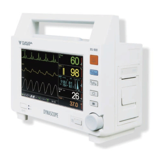
Chapter 1 General Description This chapter describes the outline of this equipment. General Description ······························ 1-2 Features·········································· 1-3 Name of Parts and Their Functions ········ 1-4 ●Front Side ································ 1-4 ●Rear Side ································ 1-5 ●Right Side ································ 1-5 ●Left Side ·································· 1-6 -... - Page 44 General Description Although the DSL-8001 system is compact, it is capable of measuring ECG, HR, RESP (impedance), SpO , pulse wave, NIBP, PR, and TEMP using a 7-inch color LCD panel. It can operate on battery power (up to 5 hours) and it can also be used as a transport monitor.
- Page 45 Features The compact, lightweight unit weighs approximately 3.0kg. Operations can be performed easily using the jog dial and fixed keys. There are fixed keys for [Alarm Silence], [NIBP Start/Stop], [NIBP Auto Mode], [Home], [Menu], and [Print]. Measuring parameters are ECG, HR, Impedance RESP, SpO , pulse wave, NIBP, PR, and TEMP.
- Page 46 Name of Parts and Their Functions ●Front Side 1. Alarm Indicator 5. Fixed Keys 2. Power Supply LED 6. Jog Dial 3. Power Switch 4. Battery LED 7. Print Key 1. Alarm Indicator Lights or flashes when an alarm generates. 2.
- Page 47 ●Rear Side 8. Maintenance 9. Battery Cover Cover 10. Power Supply Connector 11. Potential Equalization Terminal 8. Maintenance Cover Used for maintenance of this unit. 9. Battery Cover Stores the battery during battery operation. 10. Power Supply Connector Connects the power supply cable. 11.
- Page 48 ●Left Side Do not connect units or cables which are not authorized by Fukuda Denshi to any I/O connectors. If done so by mistake, the device cannot deliver its maximum performance and the WARNING connected units may be damaged, resulting in a safety hazard.
- Page 49 The use of alarm output function needs to be tested after it has been set up in your facility. It should be tested whenever setting up the DSL-8001 system in a location that uses the alarm system. One CAUTION way to test alarm output function is to create an alarm condition and verify that your facility’s alarm system is activated.
- Page 50 -...
-
Page 51: Basic Operation
Chapter 2 Basic Operation This section explains the basic operation procedure. Setup Menu ··································· 2-25 Patient Setup ·························· 2-25 Basic Operation for Monitoring ············· 2-2 Sound Setup ··························· 2-25 Fixed Keys Control ···························· 2-2 Display Setup ·························· 2-25 Jog Dial Control ································ 2-3 Alarm Setup ····························... -
Page 52: Basic Operation For Monitoring
Basic Operation for Monitoring All operations of this equipment are performed using the fixed keys and jog dial. Fixed Keys Control Fixed keys are the six keys located on the right side of the display. The frequently used or important functions are assigned to the fixed keys to allow direct access. -
Page 53: Jog Dial Control
・Menu Key Displays the Main Menu. The main menu includes Patient Setup, Sound Setup, Display Setup, Alarm Setup, Parameter Setup, Printing Setup, Data Setup, Initial Setup, and Maintenance. ・Print Key The waveform and numeric data will be printed when this key is pressed. Jog Dial Control The jog dial can be used for menu operation. -
Page 54: The Jog Dial Marker
●How to display the jog dial marker The jog dial marker (i.e. a white frame indicating the operation target of the jog dial) is usually hidden while the Home Display is being displayed. Turning the jog dial while the jog dial marker is hidden will make the jog dial marker appear on the display. - Page 55 Move the jog dial marker to the NIBP numeric data box and press the jog dial. NIBP Numeric Data ”NIBP Setup (1/2)” window will be displayed. Highlighted in blue The selected item is highlighted in blue. Turn the jog dial to move the selected item (highlighted in blue). Press the jog dial to finalize the selection.
- Page 56 Setup (2/2)” window). -...
-
Page 57: Preparation For Monitoring
Preparation for Monitoring This section describes how to turn ON/OFF the power. Use only the accompanying 3-way AC power cable. Use of other cables may result in electric shock to the patient and the operator. The power cable must be connected to a hospital grade outlet. -
Page 58: To Turn On/Off The Power
To Turn ON/OFF the Power ●Turn ON the power When the AC power is supplied to the monitor, power supply LED will light to notify it. Pressing the power switch for 2 seconds or more will start the system and display the home display or discharge confirmation screen. -
Page 59: To Start And Stop The Monitoring
To Start and Stop the Monitoring This section describes the setup necessary before monitoring and how to start patient monitoring, to suspend monitoring, and to discharge a patient, after power When lifting this equipment, hold it by the handle or the bottom part of the main unit. -
Page 60: Date/Time Setup
●Date/Time Setup Follow the procedure below to adjust the current date/time. The time/date must be set before monitoring. If the time/date is changed during monitoring, error may be caused to the trend data. If the time/date is not correctly set, or changed during CAUTION monitoring, malfunction may occur with NIBP measurement, periodic printing, and table/trend data. -
Page 61: Initial Setup
Next, set the time. Select “Time” on the “Date/Time Setup” window. The "Time" window will be displayed. Select hour, minute, or second to change the setting. When the numeric turns yellow, turn the jog dial to change the setting. Press the jog dial to finalize the setup. ●Initial Setup Depending on the used network system, perform “Telemeter Setup”. -
Page 62: To The Patient
●Attaching Electrodes to the Patient Attach the lead cable and sensor to the patient. For details, refer to “3. Vital Application”. Reference To Start Monitoring The waveform and numeric data will be displayed when the lead cables and sensors are attached to the patient. Set the patient classification, pacemaker use on the “Patient Setup”... -
Page 63: To Suspend Monitoring
To Suspend Monitoring The monitor suspend function temporarily stops all measurement function, external output functions, and table and trend data storage. <Monitor Suspended> is displayed on the window during monitor suspend condition and operation other than [Resume] key will be deactivated. Press the (Menu) key, and select “Patient Setup”... -
Page 64: Displayed Screen
Displayed Screen This section describes about the displayed screen. Types of Displayed Screens The types of displayed screens are home display, table display, trend display, and setup windows. Home Display The home display is the basic display to monitor the patient and displays waveforms and measurement value. -
Page 65: Standard Mode
Standard Mode 6 7 8 9 10 11 12 13 Waveform 1 Display Area Displays the waveform set for each display area. By selecting the waveform display area (aligning Waveform 2 Display Area the jog dial marker to the display area), “Display Waveform 3 Display Area Setup”... -
Page 66: Zoom Mode
Zoom Mode Select the Switch Display icon to switch to the zoom mode. 7 8 9 10 11 12 13 14 Waveform 1 Display Area Displays the Waveform 1. When selected, displays the “Display Setup” window. NIBP Numeric Data Box Displays NIBP numeric data. -
Page 67: Auto Zoom Mode
Auto Zoom Mode If the ECG cable is disconnected for 10 seconds or more during operation, the home display will automatically switch to auto zoom mode. Also, if the ECG cable is connected during the auto zoom mode, the display mode returns automatically to the zoom mode. -
Page 68: Icons Displayed On The Window
●Icons Displayed on the Window On the home display, various icons are displayed. This section describes the displayed icons. 1 2 3 4 5 6 Remaining Battery Power Displays the remaining battery level. Icon (Green): Full (Green): In use (Yellow): Low battery (The remaining operation time is 15 minutes or less.) (Red):... - Page 69 Time Display Area Displays the current time. Displays “Date/Time Setup” window. HR Synchronized Icon Displays a heart mark synchronized to the heart beat. NIBP Elapsed Time Icon Displays the elapsed time from the previous NIBP measurement. SEC Alarm Indicator Displayed when the SEC alarm is set. -...
- Page 70 Table Display If the numeric data is displayed on the home display, the data every minute, at NIBP measurement, and at alarm occurrence will be stored and displayed as table data. Display interval, condition, and order can be changed on the “Table Setup” window.
-
Page 71: Trend Display
Trend Display If the numeric data is displayed on the home display, the data every minute, at NIBP measurement, and at alarm occurrence will be stored and displayed as trend data. Display time width, display scale, and ON/OFF of each parameter can be changed on the “Trend Setup”... -
Page 72: Setup Window
Setup Window Various setup windows are displayed in the waveform area. The waveform on the waveform 1 display area will always be displayed. If no operation is performed during the set duration (10/20/30/60/ sec.) for “Auto Hide Window”, the setup window will disappear and the home display will appear. By selecting [Return], the previous window will appear. -
Page 73: Window
●NIBP Measurement Interval Setup Window “Measurement Interval Setup” window can be displayed by pressing the key. On the window, the current interval will be in selected state. The following items are displayed on the “Measurement Interval Setup” window. Classification Item Note Interval Cont. -
Page 74: Main Menu
Main Menu This section describes about the Main Menu and its various setups. How to Display Main Menu This section describes how to display the “Main Menu” window. The “Main Menu” is the entrance for all setups. By pressing the (Menu) key, the “Main Menu”... -
Page 75: Setup Menu
Setup Menu This section describes the setup windows displayed from the “Main Menu”. Patient Setup (Menu) key > “Patient Setup” Admit and discharge of the patient and suspend monitoring can be performed. Reference “4. Monitoring Setup/Patient Setup” Sound Setup (Menu) key > “Sound Setup” Sound setups such as operating sound volume and alarm sound volume can be performed. -
Page 76: Alarm Setup
Alarm Setup (Menu) key > “Alarm Setup” Alarm setups such as alarm limit and alarm limit display can be performed. Reference “4. Monitoring Setup/Alarm Setup” Parameter Setup (Menu) key > “Parameter Setup” Setups for each monitoring parameters can be performed. Reference “5. -
Page 77: Data Setup
Data Setup (Menu) key > “Data Setup” Table and trend setups can be performed. Reference “6. Functions” Initial Setup (Menu) key > “Initial Setup” Initial setups which are required before monitoring can be performed. Reference Date/Time Setup: “Preparation for Monitoring” in this section Other Setups: “7 Installation"... -
Page 78: Alarm Function
Alarm Function This section describes about the alarm function. On a wireless network, the alarm generated on this unit will be transmitted to the central monitor with a maximum of 15 seconds CAUTION delay. Alarm Level and Alarm Tone Depending on the alarm level, sound, color, and alarm indicator will differ. Alarm Characters Alarm Level... -
Page 79: Displayed Message
Displayed Message For details about the displayed message, refer to “9. Technical Reference Information Message List”. Ventilator Alarm When ventilator is connected to the patient monitor, ventilator alarm and the connection status alarm will be generated. Example: "Vent. Alarm” or “Vent. Invalid” Vital Alarm When the measurement value exceeds the preprogrammed alarm limit for the waveform and measurement value of the monitoring patient, the alarm... -
Page 80: Parameter Alarm
●Parameter Alarm For each parameter, ON/OFF of alarm and upper/lower alarm limit can be set. When the set limit is exceeded, an alarm will generate. Set the appropriate upper and lower alarm limit for each parameter according to the monitoring condition. ... -
Page 81: Alarm Occurrence
Alarm Occurrence ●Alarm Occurrence When the alarm occurs, it will be notified by a message display and an alarm indicator. If more than one alarm is generated, alarm messages will be alternately displayed in 2-second intervals. When a vital alarm occurs, the value inside the numeric data box will alternately reverse between red and black. -
Page 82: To Suspend The Alarm Sound
To resume the alarm sound for all parameters The alarm silence state will cease in the event of any of the following. ・ When the power is turned ON. ・ When the patient is discharged. ・ When the (Alarm Silence) key is pressed. To resume the alarm sound for each parameter The alarm silence state will cease when the alarm of each parameter is set to OFF. -
Page 83: Ventilator Alarm Input
Ventilator Alarm Input By connecting a ventilator (Servo-i/Servo-s) to the serial connector (COM1/COM2) of this unit, ventilator alarm and the connection status alarm will be generated. Also, ventilator alarm can be notified to the central monitor via wireless network. Ventilator Icon For details, refer to “7. -
Page 84: Ventilator Alarm Message
The ventilator operation should be performed by a well-trained or authorized person. When connecting this equipment and a ventilator, use only the specified connection cable. Verify that this equipment and the ventilator are properly CAUTION connected. When connecting the cable, verify that the main power of this equipment and the ventilator are OFF. -
Page 85: Printing
Printing The DSL-8001R is equipped with a built-in printer to print the monitoring waveform. To Start/Stop the Printing Press the (Print) key to start printing. If pressed during printing, printing will stop. Alarm printing and periodic printing will automatically start on the specified condition. -
Page 86: Manual Printing
Manual Printing For manual printing (standard printing), pressing the (Print) key will start / stop the printing. Pressing the key during alarm or table printing will stop the printing. The waveform and measurement value are printed from the time when the (Print) key is pressed. -
Page 87: Trend Printing
Trend Printing Pressing the (Print) key while the trend is displayed will print the displayed trend data. When the (Print) key is pressed, the displayed trend data will be printed in two divided sections as indicated below. 60 data can be printed. Header of Each Printing On the first page of each printing, the following information will be printed. - Page 88 For details, refer to “4. Monitoring Setup/Printing Setup”. Reference -...
-
Page 89: To Install The Paper
To Install the Paper When installing the printing paper, pay attention not to touch the thermal head or sensor. The temperature of those parts rises immediately after printing and may cause burn injury. Also, it may CAUTION cause failure to the thermal head and sensor. 1. - Page 90 -...
-
Page 91: Vital Application
Chapter 3 Vital Application Describes the procedure for vital application. To Acquire ECG Waveform ···················· 3-2 Before Attaching the Electrodes (Disposable Electrodes)······················ 3-2 Electrode Placement ·························· 3-3 For 3-electrode lead (1 waveform monitoring) ················ 3-3 For 4-electrode lead (Max. simultaneous 2 waveforms monitoring) ··································... -
Page 92: To Acquire Ecg Waveform
To Acquire ECG Waveform This section describes the procedure to attach the electrode to the patient, to connect the lead cable to the main unit, to set the ECG signal filter, and about the electrode types. This equipment does not have an arrhythmia analysis function. -
Page 93: Electrode Placement
Electrode Placement Verify proper electrode placement, lead, waveform size, and filter mode selection. If not properly selected, it may cause CAUTION erroneous detection. There are 3-electrode, 4-electrode, and 5-electrode applications depending on the cable type. Also, the displayed lead type can be changed. For 3-electrode lead (1 waveform monitoring) Lead Type... -
Page 94: For 5-Electrode Lead
For 5-electrode lead (Max. simultaneous 2 waveforms monitoring) Lead Type I / II / III / aVR / aVL / aVF / V Symbol Color Electrode Site On the right infraclavicular fossa On the left infraclavicular Yellow fossa On the left midclavicular line, Green near the supracrestal line On the right midclavicular... -
Page 95: Connection To The Patient Monitor
Connection to the Patient Monitor As a general guideline, electrodes can be continuously used for about 1 day. Replace the electrode if the skin contact gets loose due to perspiration, etc. When an electrode is attached at the same location for a long CAUTION time, some patients may develop skin irritation. - Page 96 4. Plug in the relay cable to the ECG connector (green) on the DSL-8001. ECG waveform and HR data will be displayed on the monitor. 5. Adjust the size and position depending on the waveform and change the monitoring lead. For waveform size / lead setup, refer to “5.
-
Page 97: Filter Mode Setup
Filter Mode Setup The waveform frequency characteristic can be selected from “Monitor Mode”, “ESIS Mode”, or “Diagnosis Mode” according to the monitoring purpose. (1) Diagnosis Mode (Frequency Characteristics: 0.05-40Hz) As the low frequency is set to 0.05Hz, select this mode when monitoring an ECG with low frequency component. -
Page 98: Respiration (Impedance Measurement)
Respiration (Impedance Measurement) This section describes how to acquire a respiration waveform. When a defibrillator is used during respiration monitoring, a large offset voltage will be placed on the ECG electrodes, which may CAUTION cause interruption of monitoring for a few seconds. 1. -
Page 99: To Measure The Spo
Patient with small pulse Do not connect a sensor or cable which is not authorized by Fukuda Denshi to any I/O connector. If done so by mistake, the equipment cannot deliver its maximum performance and the connected units may be damaged, resulting in a safety hazard. - Page 100 When not performing the measurement, unplug the relay cable and sensor from the SpO connector. Otherwise, the measurement data may be erroneously displayed by the ambient light. For additional warnings, cautions, or contraindications when using sensors with the DSL-8001, refer to each SpO sensor instruction manual.
- Page 101 2. Attach the sensor to the DSL-8001. (1) Connect the DOC-10 SpO Relay Cable to the SpO connector on the DSL-8001. (2) Insert the sensor into the SpO relay cable connector, and lock it with the transparent part. 3. Attach the sensor to the patient. If the nail is rough, dirty, or manicured, accurate measurement will not be possible.
- Page 102 (2) Adjust the sensor so that the light-emitting part (on cable side) touches the root of the nail, and close the probe. (3) Press the probe lightly so that the finger and the rubber cover are appressed. This is to stabilize the probe, and to avoid ambient light.
- Page 103 4. Verify that the SpO measurement and SpO waveform are displayed on the home display. For setup procedure, refer to “5. Parameter Setup/SpO Setup”. Reference -...
-
Page 104: To Measure The Nibp
To Measure the NIBP This section describes the types and attachment procedure of the cuff and NIBP measurement. Before the measurement, make sure the patient classification (Adult/Child/Neonate) on the monitor is properly selected. Otherwise, correct measurement cannot be performed, and WARNING congestion or other injury may result. - Page 105 1. Select the appropriate cuff type for the patient. According to the AHA (American Heart Association) guideline, the appropriate cuff width is 40% of the arm circumference. For details of the cuffs that can be used, refer to "10. Accessories/ Reference Optional Accessories/Non-Invasive Blood Pressure Measurement".
- Page 106 4. Attach the cuff to the patient. Position the artery mark ▼ over the artery on the patient’s arm and wrap the cuff around. One or two fingers should just fit in between the cuff and arm. Mark Align the cuff height with the heart position.
-
Page 107: Procedure For Periodic Measurement
About the Oscillometric Method The oscillometric method measures the blood pressure by detecting the pulse oscillation change with the cuff pressure. The cuff connects to the NIBP cuff connector on the monitor via the air hose. The air pressure inside the cuff is converted to electrical voltage by the pressure sensor, converted into a digital signal (A/D conversion), and communicated to the CPU section. - Page 108 When [1] is selected, the 1-minute interval measurement will start from the time the selection is made. The measurement will automatically stop after 12 minutes (maximum of 15 minutes when re-measured), and 2.5-minutes interval measurement will be set. Selecting [Cont.] will start the continuous measurement. The CAUTION measurement will automatically stop after 12 minutes (maximum of 15 minutes when re-measured), and...
-
Page 109: To Measure The Temperature
To Measure the Temperature This section describes the types and attachment procedure of the probes. 1. Select an appropriate type of probe for the patient. Probe Type Reusable Type Rectal Probe (adult) 401 Rectal Probe (pediatric) 402 Body Surface Probe 409B * 400 series general purpose temperature probe, manufactured by Measurement Specialties, Inc. - Page 110 2. Connect the probe to the DSL-8001. 3. Attach the probe to the patient. ●For Body Surface Probe 409B Attach the probe to the body surface, and secure it with surgical tape. The probe location shown above is an example. Adjust the probe NOTE location according to the patient’s condition.
- Page 111 ●For Rectal Probe 401 and 402 (1) Clean/disinfect/sterilize the probe according to the guidelines provided with the probe product. (2) Insert the probe into the rectum about 3 to 7 cm deep. (3) Secure the probe to inner 401, 402 thigh with surgical tape.
- Page 112 -...
-
Page 113: Monitoring Setup
Chapter 4 Monitoring Setup Describes the procedures to set the monitor according to the monitoring purpose. Patient Setup ······································· 4-2 Alarm Setup ······································ 4-13 Admit the patient ······························· 4-2 NIBP Measurement at Alarm ············· 4-13 Alarm Limit Display ·························· 4-13 ●Patient Classification ··················... -
Page 114: Patient Setup
Patient Setup This section describes about the admit procedure (patient classification, pacemaker) and how to suspend monitoring, to set the night mode, and to discharge a patient. This unit cannot display the patient information (patient ID, patient name, etc.) received from the central monitor, even when a CAUTION wireless network system is constructed. -
Page 115: Pacemaker
●Pacemaker If [ON] is selected for "Pacemaker", the monitor will detect the pacing pulse (pacemaker pulse) to perform the following process. ・ The artificial pacemaker pulse will be displayed. ・ When pacing waveform does not appear (pacing failure), erroneously detecting the pacemaker pulse as QRS will be prevented. 1 Press the (Menu) key, and select “Patient Setup”. -
Page 116: Night Mode
Night Mode The night mode can be used when turning off the light of the ward or when the patient is asleep. The night mode can be manually set to ON, or automatically set to ON by preprogramming the time to turn ON/OFF the night mode. To use the night mode, it is necessary to perform the setup in advance. -
Page 117: Discharge
Discharge By performing the discharge process, the previous data such as table and trend data will be deleted and the settings will be initialized. If monitoring of new patient is started without discharging the previous patient, the measurement data of the previous and new patient will become mixed up on the table and trend data. -
Page 118: Sound Setup
Sound Setup The following items related to sounds can be set. ・Operating Sound Volume ・Sync Sound Volume ・Alarm Sound Volume ・Boot / Shutdown Sound Volume ・Other Sound Volume ・Alarm Sound Pattern ・Sync Sound Pattern Operating Sound Volume The volume of the jog dial operating sound can be set. Press the (Menu) key, and select “Sound Setup”... -
Page 119: Alarm Sound Volume
Alarm Sound Volume The volume of the alarm sound can be set. The same volume will be set for all alarm levels. Press the (Menu) key, and select “Sound Setup” >“Alarm Sound Volume”. The "Alarm Sound Volume" window will be displayed. Select the alarm sound volume level. -
Page 120: Other Sound Volume
Other Sound Volume The volume of the NIBP measurement end tone and boot/shutdown sound can be set. Press the (Menu) key, and select “Sound Setup” >“Other Sound Volume”. The "Other Sound Volume" window will be displayed. Select the other sound volume level. The volume will increase with the value respectively. -
Page 121: Sync Sound Pattern
Sync Sound Pattern HR synchronizing sound can be changed. A higher frequency tone will be generated for pattern 2 compared to pattern 1. Press the (Menu) key, and select “Sound Setup” > “Sync Sound Pattern”. Select [Pattern 1] or [Pattern 2]. -... -
Page 122: Display Setup
Display Setup The following items can be set on the “Display Setup”. ・Parameter for displaying waveform ・Waveform Sweep Speed ・ON/OFF of Auto Zoom Mode ・ON/OFF of Auto Hide Window ・Color setup for each parameter ・Brightness of the display Waveform Parameter The parameter for the displaying waveform can be set. -
Page 123: Auto Zoom Mode Setup
Auto Zoom Mode Setup The auto zoom function can be used by selecting [ON] for “Auto Zoom Mode”. The home display will automatically switch to zoom mode if the ECG cable is disconnected for 10 seconds or more. For details about the auto zoom mode, refer to “2. Basic Operation/ Reference Displayed Screen”. -
Page 124: Color Setup
Color Setup The displayed colors of the waveform and numeric data and the screen brightness can be set. ●Color Setup The set color will be applied to the following item. Waveform, Numeric Data, Synchronized Mark, Waveform Area Label, Numeric Data Box Label, Numeric Data Unit, Alarm Level Indicator Waveform, Numeric Data, Synchronized Mark, Waveform Area RESP... -
Page 125: Alarm Setup
Alarm Setup On the “Alarm Setup”, ON/OFF of NIBP measurement at alarm occurrence, alarm limit display type, and alarm limit level can be set. NIBP Measurement at Alarm Select whether to perform NIBP measurement at alarm occurrence. Press the (Menu) key, and select “Alarm Setup” >“NIBP Measurement at Alarm”. -
Page 126: Alarm Limit Setup
Select the display type. [OFF] : Alarm limit will not be displayed. [Numerical Value] : Alarm limit will be displayed in numeric format. [Graph Bar] : Alarm limit will be displayed in bar graph. Alarm Limit Setup The alarm for each parameter can be turned ON or OFF, and upper and lower alarm limit can be set. - Page 127 The selectable alarm limit ranges are as follows. Item Upper range Lower range Increment HR/PR Adult OFF, 25 to 300 bpm OFF, 20 to 295 bpm 5 bpm Child OFF, 25 to 300 bpm OFF, 20 to 295 bpm Neonate OFF, 40 to 300 bpm OFF, 35 to 295 bpm RESP...
-
Page 128: Printing Setup
Printing Setup This section describes the procedure to set the printing speed, manual printing, alarm printing, and periodic printing. Printing Speed Set the printing speed. The same printing speed will be applied to manual, alarm, and periodic printing. Press the (Menu) key, and select “Printing Setup”... -
Page 129: Manual Printing Setup
Manual Printing Setup The following can be set for manual printing. ・ Output Printer (Built-in / Center) ・ Printing Waveform (OFF / ECG1 / ECG2 / RESP / SpO ・ Printing Duration (24 sec./cont) ・ Delay Time (0 sec./8 sec./16 sec.) ●Output Printer Press the (Menu) key, and select “Printing Setup”... -
Page 130: Printing Duration
●Printing Duration Press the (Menu) key, and select “Printing Setup” > “Manual Printing Setup” > “Printing Duration”. Select [24 sec.] or [Cont.]. [24 sec.] : Printing will automatically stop after 24 seconds. [Cont.] : Printing will continue until the (Print) key is pressed again. ●Delay Time Press the (Menu) key, and select “Printing Setup”... -
Page 131: Alarm Printing Setup
Alarm Printing Setup The following can be set for alarm printing. ・ Alarm Printing (ON/OFF) ・ Output Printer (Built-in / Center) ・ Printing Waveform (OFF / ECG1 / ECG2 / RESP / SpO ・ Cause for Printing (ALL / HR/PR / Measurement Value) ・... -
Page 132: Printing Waveform
●Printing Waveform Select the waveform for printing. Press the (Menu) key, and select “Printing Setup” > “Alarm Printing Setup” > “Printing Waveform 1”. The “Printing Waveform 1” window will be displayed. Select the parameter to print. Select from Alarm / ECG1 / ECG2 / RESP / SpO2. Set the parameter for “Printing Waveform 2”... -
Page 133: Printing Duration
●Printing Duration Set the printing duration for alarm printing. After 12 seconds/24 seconds, the printing will automatically stop. Press the (Menu) key, and select “Printing Setup” > “Alarm Printing Setup” > “Printing Duration”. Select [12 sec.] or [24 sec.]. -... -
Page 134: Periodic Printing Setup
Periodic Printing Setup The following can be set for periodic printing. ・ Periodic Printing (ON/OFF) ・ Output Printer (Built-in / Center) ・ Printing Waveform (OFF / ECG1 / ECG2 / RESP / SpO ・ Printing Duration (6 sec./12 sec./24 sec.) ・... -
Page 135: Printing Waveform
●Printing Waveform Select the waveform for printing. Press the (Menu) key, and select “Printing Setup” > “Periodic Printing Setup” > “Printing Waveform 1”. The "Printing Waveform 1" window will be displayed. Select the parameter to print. (OFF/ECG1/ECG2/RESP/SpO2) Set the parameter for “Printing Waveform 2” and “Printing Waveform 3” using the same procedure. -
Page 136: Printing Interval
●Printing Interval Select the printing interval for the periodic printing. Press the (Menu) key, and select “Printing Setup” > “Periodic Printing Setup” > “Printing Interval”. The “Printing Interval” window will be displayed. Select the printing interval. (5 min. / 10 min. / 15 min. / 30 min. / 60 min. / 120 min.) For example, if [5 min] is selected, the time will be displayed in real time such as 10:00, 10:05, ...10:25. -
Page 137: Parameter Setup
Chapter 5 Parameter Setup HR/PR Setup ········································ 5-2 RESP Setup ······································· 5-16 ECG Lead ········································ 5-2 RESP Measurement ························ 5-16 ECG Size ········································· 5-2 RESP Size····································· 5-16 Filter Mode ······································· 5-3 RESP Alarm··································· 5-17 HR/PR Source ·································· 5-3 RR Zero Alarm ······························· 5-18 HR/PR Alarm ····································... -
Page 138: Pr Setup
HR/PR Setup This section describes the setup procedure for ECG lead, ECG size, filter mode, and pacemaker pulse. ECG Lead Set the monitoring lead. 1 Press the (Menu) key, and select “Parameter Setup” > “HR/PR Setup” > “ECG1 Lead”. The "ECG1 Lead" window will be displayed. -
Page 139: Filter Mode
Filter Mode Select the filter mode from “Monitor Mode”, “ESIS Mode”, or “Diagnosis Mode” according to the monitoring purpose. Each mode has different frequency characteristic. The selected filter mode will be printed along with other data. 1 Press the (Menu) key, and select “Parameter Setup” > “HR/PR Setup” >... -
Page 140: Pr Alarm
HR/PR Alarm ON/OFF of HR/PR alarm and alarm limit can be set. 1 Press the (Menu) key, and select “Parameter Setup” > “HR/PR Setup” > “HR/PR Alarm”. Select [ON] or [OFF]. Next, set the alarm limit. Select the "Alarm Limit Setup" to display the “Alarm Limit Setup” window. (1) Select a parameter for setup. -
Page 141: Pacemaker Pulse
Pacemaker Pulse The artificial pacemaker pulse can be superimposed on the ECG waveform and displayed in yellow color. During waveform printing, the displayed artificial pacemaker pulse will be also printed along with the waveform. Pacemaker Pulse Detection Algorithm (1) ECG Signal Input ECG signal will be input. - Page 142 1 Press the (Menu) key, and select “Parameter Setup” > “HR/PR Setup” > “Pacemaker Pulse”. Select [ON] or [OFF]. [ON] : The artificial pacemaker pulse will be displayed in yellow color. "Pacemaker Pulse" will be automatically set to [ON] when [ON] is selected for "Pacemaker"...
-
Page 143: Spo 2 Setup
Setup This section describes the setup procedure for C-LOCK, SEC alarm, SpO alarm, and alarm generation at NIBP measurement. The SEC alarm function utilizes SatSeconds technology of NOTE Covidien. SatSeconds is a trademark of Covidien. C-LOCK The C-LOCK function uses the ECG R-wave as the synchronized signal to increase the SpO measurement accuracy. - Page 144 On this graph, the SEC alarm threshold value is set as 100. The SpO value begins to fall below the alarm limit at approximately 10 seconds. At the same time, the integral value begins to increase. (Alarm limit) – (SpO value) is accumulated each second.
-
Page 145: Spo 2 Alarm
Alarm Select ON/OFF of SpO alarm, and set the alarm limit. Press the (Menu) key, and select “Parameter Setup” > “SpO2 Setup” > “SpO2 Alarm”. Select [ON] or [OFF]. Next, set the alarm limit. Select the "Alarm Limit Setup" to display the “Alarm Limit Setup” window. (1) Select a parameter for setup. -
Page 146: Alarm At Nibp Measuring
Alarm at NIBP Measuring When the SpO sensor and the NIBP cuff are placed on the same limb for measurement, an improper alarm may be generated because the cuff inflation restricts the blood flow which disables the correct detection of the SpO and PR during the NIBP measurement. -
Page 147: Nibp Setup
NIBP Setup This section describes the following items related to the NIBP measurement. - Quick Measurement - Sight Inflation - Pump Operation Mode - PR Display - Oscillation Graph Display - Notification of Measurement - Measurement Interval Setup - Pressure Unit - NIBP Alarm Quick Measurement Select the measurement duration. -
Page 148: Sight Inflation
Sight Inflation When “Sight Inflation” is set to ON, the inflation target level will be automatically estimated during the inflation, and starts to deflate after the target level is reached. The inflation speed is slow but allows to detect any sudden increase of blood pressure to prevent re-inflation and discomfort for the patient. -
Page 149: Pr Display
PR Display The pulse rate measured during NIBP measurement can be displayed. This pulse rate is only for display. It will not generate alarm, or be displayed on the table function. Pulse Rate Press the (Menu) key, and select “Parameter Setup” > “NIBP Setup” >... -
Page 150: Pressure Setup
Pressure Setup Select the pressure unit. Press the (Menu) key, and select “Parameter Setup” > “NIBP Setup” > “Pressure Unit”. Select [mmHg] or [kPa]. Notification of Measurement By setting this function ON, the start of NIBP measurement will be notified by message and sound. -
Page 151: Nibp Data Display Time
NIBP Data Display Time Select the numeric data display duration (60min. / 120min.) inside the NIBP numeric data box. The data will be deleted after the selected duration. Press the (Menu) key, and select “Parameter Setup” > “NIBP Setup (2/2) > “NIBP Data Display Time”. Select [60 min.] or [120 min.]. -
Page 152: Resp Setup
RESP Setup This section describes the setup procedure for RESP measurement, RESP size, RESP alarm, RR zero alarm, and RR zero alarm limit. RESP Measurement Select whether or not to perform the RESP measurement. Press the (Menu) key, and select “Parameter Setup” > “RESP Setup” >... -
Page 153: Resp Alarm
RESP Alarm Select ON/OFF of RESP alarm, and set the alarm limit. Press the (Menu) key, and select “Parameter Setup” > “RESP Setup” > “RESP Alarm”. Select [ON] or [OFF]. Next, set the alarm limit. Select "Alarm Limit Setup" to display the “Alarm Limit Setup” window. (1) Select a parameter for setup. -
Page 154: Rr Zero Alarm
RR Zero Alarm Select whether or not to use the RR zero alarm function. Press the (Menu) key, and select “Parameter Setup” > “RESP Setup” > “RR zero Alarm”. Select [ON] or [OFF]. [ON] will generate an alarm when the RR value is zero. The threshold to generate the RR zero alarm can be set on “RR zero Alarm Limit”... -
Page 155: Temp Setup
TEMP Setup This section describes the setup procedure of temperature unit and TEMP alarm. Temperature Unit 1 Press the (Menu) key, and select “Parameter Setup” > “TEMP Setup” > “Temperature Unit”. Select [°C] or [°F]. TEMP Alarm Select ON/OFF of TEMP alarm, and set the alarm limit. Press the (Menu) key and select “Parameter Setup”... - Page 156 (1) Select a parameter for setup. (2) Select [ON] / [OFF] for the alarm. If [OFF] is selected, alarm will be turned OFF and (Alarm OFF) icon will be displayed. (3) Aligning the highlight and pressing the jog dial will change the numeric color to yellow enabling selection of value by turning the jog dial.
- Page 157 Chapter 6 Functions This chapter describes functions such as trends and tables. Trend ·················································· 6-2 To Display the Trend·························· 6-2 ●Description of the Trend Display ··· 6-2 Setup for Trend Display ······················ 6-3 ●Selecting the Display Time Width ·· 6-4 ●Selecting the Display Scale ·········...
-
Page 158: Trend
Trend If the numeric data is displayed on the home display, the data every minute, at NIBP measurement, and at alarm occurrence will be stored and displayed as trend data. Maximum of 20,480 trend data can be displayed. This section explains the operations of the trend display. To Display the Trend Select the (Table/Trend) icon. -
Page 159: Setup For Trend Display
Trend Bar The position and proportion of the stored data are displayed through the position and width of the slider. (1) Stored data (2) Displayed trend data (3) Unused portion which the data is not stored Next Screen Displays next trend data. Newest Screen Displays the newest trend data. -
Page 160: Selecting The Display Time Width
●Selecting the Display Time Width The time width displayed on the trend window can be selected from 1 hour, 2 hours, 4 hours, 8 hours, 12 hours, and 24 hours. Select “Display Time Width” on the “Trend Setup” window. The “Display Time Width” window will be displayed. -
Page 161: Selecting The Parameter
●Selecting the Parameter The parameters for the trend display can be selected from HR/PR, SpO , NIBP, RESP, or TEMP. On the “Trend Setup” window, select the “xx Trend Display” for the parameter to change the display ON/OFF setting. Select [ON] or [OF]. Select [ON] to display the parameter, and select [OFF] to not display the parameter. -
Page 162: Table
Table If the numeric data is displayed on the home display, the data every minute, at NIBP measurement, and at alarm occurrence will be stored and displayed as table data. Maximum of 20,480 table data can be displayed. This section describes operations and printing procedure of the table display. To Display the Table Select the (Table/Trend) icon. -
Page 163: Setup For Table Display
minutes/30 minutes/60 minutes Data at Alarm The data at alarm occurrence will be displayed with a Occurrence red background color. ↑: upper limit has been exceeded ↓: lower limit has been exceeded Previous Screen Displays previous table data. Display If the jog dial is continuously pressed, the display will keep on scrolling. -
Page 164: Selecting The Display Interval
●Selecting the Display Interval The display interval for the table display can be selected from 1 minute, 2 minutes, 5 minutes, 10 minutes, 15 minutes, 30 minutes, or 60 minutes. Select “Display Interval” on the “Table Setup” window. The “Display Interval” window will be displayed. -
Page 165: Changing The Display Order
●Changing the Display Order The display order of the table can be selected from “Ascending or “Descending”. When the display order is ascending, the newest data will be added at the bottom of the table. When the display order is descending, the newest data will be added at the top of the table. - Page 166 -...
- Page 167 Chapter 7 Installation Precautions for Installing the Equipment 7-2 Precautions about the Operating Environment····································· 7-2 Power Source and Ground Connection ··· 7-4 Connecting the DSL-8001 to the Power Source··································· 7-4 Equipotential Grounding ····················· 7-5 Battery Operation ································· 7-6 To Charge the Battery ························ 7-6 Wireless Network System Construction ··...
- Page 168 Precautions for Installing the Equipment This section describes the environmental condition to use the DSL-8001. The installation of this equipment should be performed by our service representative or a person who is well acquainted with CAUTION this equipment. Precautions about the Operating Environment ...
- Page 169 Equipotential Grounding When connecting multiple equipments, electrical potential difference may be generated between the equipments. This may result in electric shock to the patient connected to these equipments. Pay special attention for use in Operating Room, CAUTION ICU, CCU, Cardiac Catheter Laboratory, and Cardiovascular X-ray room.
- Page 170 Power Source and Ground Connection Connect the DSL-8001 to the power source. Connecting the DSL-8001 to the Power Source Connect the power cable to the power supply connector on the rear of the main unit. Connect the other end of the power cable to the 3-way outlet with ground terminal.
- Page 171 Equipotential Grounding When connecting multiple equipments, electrical potential difference may be generated between the equipments. This may result in electric shock to the patient connected to these equipments. Pay special attention for use in Operating Room, ICU, CCU, Cardiac Catheter Laboratory, and Cardiovascular X-ray room.
- Page 172 Battery Operation Using the battery for operating the DSL-8001 allows monitoring at places where AC power source is not available such as during in-hospital patient transportation. One (1) battery can be installed inside the unit. Also, the DSL-8001 will automatically switch to battery operation for the following cases.
- Page 173 Wireless Network System Construction This section explains the procedure on how to use this equipment with telemetry system. By connecting the telemetry transmitting module (HLX-801), this system can construct a wireless network system and display the data on the central monitor. DS-7780 System Central Monitor DSL-8001 System DS-7680 System Central Monitor...
- Page 174 Connection of the HLX-801 Telemetry Transmitter Module Connection of the HLX-801 Telemetry Transmitter Module will be performed by our service representative. Users should not perform this procedure as malfunction of the equipment may CAUTION occur. Communication Setup When using the HLX-801 Telemetry Transmitter Module, it is necessary to perform communication setup in advance.
- Page 175 Channel ID and Group ID Setup The setup of channel ID and group ID should be performed only by our service representative. Users should not perform CAUTION this procedure as malfunction of the equipment may occur. It is necessary to set the channel ID in order to connect to the wireless network. Once the transmitting channel ID and group ID are programmed, these will be retained even after the main power is turned OFF.
- Page 176 Select “Save” to save the channel ID and group ID. "Password" window will be displayed. Turn the jog dial and enter the password. Press the jog dial to finalize the setup. Verify the stored channel ID and group ID. When the setup is complete, the set channel ID will be displayed. If there is an error with the channel ID, the following message will be displayed.
- Page 177 When this equipment indicates that the measurement data is out of range ( “ xxx ” display), the minimum or maximum value of the range will be displayed at the central monitor. 【Out of Range】 【Central Monitor Display】 301bpm or above Calculated on central monitor based on ECG waveform.
- Page 178 Ventilator Connection By connecting this equipment to a ventilator, ventilator alarm can be notified to the central monitor through wireless network or TCON system. This section describes the procedure to connect this equipment and ventilator, and to input the ventilator alarm. NOTE Only one ventilator can be connected for each DSL-8001 system.
- Page 179 CJ-502 Servo-i / Servo-s Turn ON the power of the DSL-8001 and ventilator. Communication Setup To monitor the ventilator alarm, ventilator needs to be assigned to the COM connector function. The same function cannot be set to multiple ports. ...
- Page 180 Select the port for the ventilator (“COM 1” or “COM 2”). Select the connected ventilator (Servo-i/Servo-s). If other function is already assigned to the COM port, it is necessary NOTE to disconnect the communication in order to change the selection. If [OFF] is selected, the ventilator message will not be displayed and ventilator alarm will not be generated.
- Page 181 Ventilator Alarm Setup Set the following items for ventilator alarm. ・ Ventilator Alarm ON/OFF ・ Alarm Judgment Time Select the (Main Menu) icon > “Initial Setup” > “VENT Setup” > “VENT Alarm”. Select [ON]/[OFF] for “VENT Alarm”. [ON] : The DSL-8001 will notify the ventilator alarm. [OFF] : The DSL-8001 will not notify the ventilator alarm even if it is generated on the ventilator.
- Page 182 -...
- Page 183 Chapter 8 Maintenance Maintenance Menu ································ 8-2 Cleaning ··········································· 8-16 How to Display the Cleaning the Display Panel ··············· 8-16 Maintenance Menu ··························· 8-2 Cleaning the Housing ······················· 8-16 Language Selection ··························· 8-3 Cleaning the NIBP Cuff Alarm Behavior Setup ························· 8-3 and Air Hose·································...
- Page 184 Maintenance Menu This section describes the setup for maintenance function. On the maintenance menu, the following setup can be performed. ・ Language Selection (Japanese / English / Spanish / French / Italian) ・ Alarm Behavior Setup ・ Backup Setup ・ Night Mode Setup ...
- Page 185 Language Selection Select the language from Japanese, English, Spanish, French, or Italian. Press the (Menu) key, select “Maintenance”, enter the password, and select “Language Select”. The “Language Select” window will be displayed. Select the language. Alarm Behavior Setup For the Alarm Behavior, the following items can be set. ・...
- Page 186 ●Alarm Sound Suspend Time By pressing the [Alarm Silence] key for 3 seconds or more, the alarm sound can be suspended in advance for a fixed duration (60 min. / 90 min. /120 min.). Alarm monitoring will continue even while the alarm sound is supended. Press the (Menu) key, and select “Maintenance”...
- Page 187 ●Alarm Indicator Select the alarm level to activate the alarm indicator. Press the (Menu) key, and select “Maintenance” > enter the password > “Alarm Behavior Setup” > “Alarm Indicator”. The “Alarm Indicator” window will be displayed. Select from [Alarm Level 1-3] / [Alarm Level 1-2] / [Alarm Level 1] / [OFF]. For example, if [Alarm Level 1] is selected, alarm indicator will activate only when the level 1 alarm occurs.
- Page 188 Backup Setup This section describes the following items related to discharge operation. ・ Check Discharge at Power ON (ON/OFF) ・ Automatic Discharge Time (OFF/10 min./1 hour/2 hours/4 hours) ・ Backup at Discharge (ON/OFF) ・ Monitor Suspend at Discharge (ON/OFF) ・ Measurement Interval at Discharge (OFF/2 min./2.5 min./5 min./10 min./15 min./30 min./60 min./120 min.) At power ON, corresponding procedures will be performed based on the setting of “Check Discharge at Power ON”...
- Page 189 ●Check Discharge at Power ON The discharge operation will be automatically performed when the power is turned ON again after the power was turned OFF for preprogrammed duration. Whether or not to display the confirmation window for the discharge operation can be selected.
-
Page 190: Alarm Behavior Setup
●Automatic Discharge Time Select the power OFF duration to automatically perform the discharge operation. Press the (Menu) key, and select “Maintenance” > enter the password > “Backup Setup” > “Automatic Discharge Time”. The “Automatic Discharge Time” window will be displayed. Select the power OFF duration for automatic discharge function. - Page 191 ●Monitor Suspend at Discharge Whether or not to suspend the monitoring when a patient is discharged can be selected. Press the (Menu) key, and select “Maintenance” > enter the password > “Backup Setup” > “Monitor Suspend at Discharge”. Select [ON]/[OFF]. If [ON] is selected, monitoring will be suspended after the discharge operation.
-
Page 192: Night Mode
Night Mode Setup The night mode is a function to decrease the screen brightness and alarm volume when turning OFF the light of the ward or when the patient is asleep, etc. The night mode can be manually set to ON, or automatically set to ON by preprogramming the time to turn ON/OFF the night mode. -
Page 193: Automatic Start Time
●Automatic Start Time When the night mode operation is set to [Auto], set the time to automatically start the night mode. Press the (Menu) key, and select “Maintenance” > enter the password > “Night Mode Setup” > “Automatic Start Time”. The “Automatic Start Time”... -
Page 194: Volume
●Volume The volume of HR synchronized sound, alarm sound, and jog dial operating sound during the night mode can be set. When selecting [Silence], pay attention not to miss any important alarm by simultaneously monitoring the patient on WARNING other monitors such as central monitor. Press the (Menu) key, and select “Maintenance”... - Page 195 Press the (Menu) key, and select “Maintenance” > enter the password > “Night Mode Setup” > “Screen Brightness”. The “Screen Brightness” window will be displayed. Select the brightness. (No Change / Slightly Dark / Dark / Time Only) [No change] : Currently set brightness will be applied.
-
Page 196: Handling
Handling This section describes precautions for handling the equipment. Handling After Use Do not apply excessive force when disconnecting the cables. Always pull on the connector housing and not on the cable. Clean the unit, accessories, and cables, and keep them together in one place for next use. -
Page 197: Storage
Storage This section explains how to store the equipment and printing paper. Storing the Equipment Store in a place where the equipment will not be exposed to splashing water. Store in a place where the equipment will not be adversely affected by atmospheric pressure, temperature, humidity, ventilation, sunlight, dust or atmosphere containing salt or sulfur. -
Page 198: Cleaning
Cleaning This section explains how to clean the equipment and sensors. Cleaning the Display Panel Use a cleaning cloth to clean the display panel. When cleaning the display panel, never use strong-acidic cleaning solution. Do not wipe the display panel with a cloth or gauze with coarse texture. - Page 199 Cleaning and Disinfecting the SpO Sensor ® [NELLCOR Sensor] Do not soak the sensor in water or antiseptic solution. Wipe the DURASENSOR with a disinfectant such as 70% alcohol. Do not disinfect by applying radioactive rays, steam, or ethylene oxide. ...
-
Page 200: Battery
Battery This section describes precautions for handling and storing the battery. Handling the Battery The battery can be continually used for more than 300 times (or about 1 year) under normal temperature, but the continuous use will degrade the battery and shorten the usable time. -
Page 201: Maintenance Check
Following maintenance check items should be performed for this equipment. To ensure safety, reliability, and high performance, a “Daily Check” and “Periodic Check” must be performed. Please be aware that Fukuda Denshi is not liable of any accidents arising from lack of daily check. -
Page 202: Periodic Replacement Parts Information
Periodic Replacement Parts Information The usage period and measurement frequency for battery and NIBP unit can be displayed. It can be used as an indication of replacement period. Press the (Menu) key, and select “Maintenance” > enter the password > “Periodic Replacement Parts Information”. The “Periodic Replacement Parts Information”... -
Page 203: Function
Daily Check List Checked Date Checked by Installation Location Equipment Type (DSL-8001/DSL-8001R) Serial Number Item Check Details Criteria Judgment External Visually check the exterior for No abnormality should be found. OK / NG appearance scratches, cracks, deformation, and rust. Installation Check whether the unit is The installation area must be level OK / NG... -
Page 204: Troubleshooting
Troubleshooting This section explains troubleshooting for each case. Other than the problems stated below, problems in the central monitor or other equipments can be considered. Refer also to the operation manual of those equipments. For electrode attachment procedure, refer to “3. Vital Application / To Acquire ECG Waveform / Before Attaching the Electrodes (Disposable Reference Electrodes), Electrode Placement”. -
Page 205: Respiration (Resp)
If the error persists, the lead cable or relay cable may be faulty. Contact our service representative. The <ECG Disconnected> message is displayed. Cause : While monitoring the ECG, the relay cable was unplugged. Solution 1 : To cease monitoring, press the (Alarm Silence) key. -
Page 206: Non-Invasive Blood Pressure (Nibp)
RESP waveform is in the baseline position. Cause : Electrode is detached. Solution : Reattach the electrode. If the electrode contact is poor, replace the electrode. The <RESP No Signal Detect> message is displayed. Cause 1 : The amplitude of the respiration waveform is too low. It is below 0.2 ohm which is outside the detection range. - Page 207 The <NIBP Check Cuff, Airhose> message is displayed. Cause 1 : The connection between the cuff and air hose or the air hose and NIBP connector is loose or disconnected. Solution : If connection is loose or disconnected, securely connect it and perform the measurement again.
- Page 208 Solution : Keep the patient still as much as possible, and measure while the patient is not moving. When performing the measurement during surgery, avoid artifact caused by the surgery. Cause 2 : During the measurement, air hose was bent or occluded by the compression.
-
Page 209: Arterial Oxygen Saturation (Spo 2 )
The <NIBP Pulse Amp. Error (C10)> message is displayed, and measurement has stopped. Cause The pulse is too small to acquire reliable measurement accuracy. Solution : Check if the cuff is properly attached to the patient, or cuff size is correct. - Page 210 : When attached to the patient, the sensor was exposed to high-intensity light which lead to false recognition. Solution : Reattach the sensor and patient cable. Replace with a Fukuda Denshi specified patient cable and sensor. The <SpO Pulse Search> message is displayed. Cause 1 : The amplitude of the pulse waveform is too low, or the sensor is not positioned correctly.
- Page 211 The <SpO No Pulse Detect> message is displayed. Cause : The amplitude of the pulse waveform is too low, or the sensor is not positioned correctly. Solution : Check if the light emitting and receiving parts of the sensor LED are aligned.
- Page 212 The measurement data is displayed as “xxx”. Cause The temperature measurement is outside the measurement range. Solution : ・ Check if the temperature probe is properly inserted. ・ Replace the temperature probe, or check the temperature probe. Alarm Alarm is not generated. Alarm message is not displayed. Cause 1 : Alarm is silenced.
- Page 213 The <Printer Communication Error> message is displayed. Cause Communication error with the recorder board has occurred. Solution : Reboot the equipment. If the same message is repeatedly displayed, a failure of the equipment can be considered. Contact our service representative. Telemeter The <HLX Module Error>...
- Page 214 Solution : Set [ON] for “VENT Alarm” (“Initial Setup” > “VENT Setup”). Battery The battery LED flashes in orange. Cause 1 : The battery life has expired. Solution : The battery is a consumable product. Replace it every year. Cause 2 : The ambient temperature is too high or too low.
- Page 215 The battery LED does not light during battery charge. Cause The battery temperature is high. Solution : For safety reasons, if the battery is charged in a repetitive manner, its temperature will be high and the charging operation will be in a standby mode until the battery temperature decreases.
- Page 216 -...
-
Page 217: Technical Information
Chapter 9 Technical Information Specification / Performance ················· 9-2 Specification ·································· 9-2 Performance ·································· 9-3 Alarm ················································ 9-7 Vital Alarm ····································· 9-7 List of Setup Items ····························· 9-8 Setup Items ··································· 9-8 Menu Levels ··························· 9-8 Setup Item (Level 1) ················· 9-9 Setup Item (Level 2) ·················... - Page 218 Specification / Performance This section states the specifications and performance of this equipment. Specification Size 225 (W) x 201(H) x 142(D) mm (not including the protrusion) Weight Approx. 3.0kg (not including accessories) Environmental Conditions : 5 to 40 C Operating Temperature Operating Humidity : 30 to 85% (non-condensing)
- Page 219 Classification Type of protection against electric shock : Class I (AC operation) Internally powered equipment (battery operation) Degree of protection against electric shock : Type CF Applied Part Protection against defibrillation discharge : Provided Degree of protection against ingress of water : IPX0 (no protection) Sterilization or disinfection method...
- Page 220 Alarm Function Alarm Sound Pressure : Maximum 80dB, Minimum 46dB Lead Type : Wired 3-electrode, 4-electrode, 5-electrode Frequency Characteristic : 40Hz/15Hz : 2.5M or more (Diagnosis mode) Input Impedance Maximum Input Voltage : 10mVp-p or above Polarization Voltage : ±500mV or above Common Mode Rejection Ratio : 90 dB or above HR Measurement Range : Adult...
-
Page 221: Temperature (Temp)
Ventricular Tachycardia 2mVpp, 206bpm Average 6.3 sec. Ventricular Tachycardia 0.5mVpp, 206bpm : Average 13.3 sec. Ventricular Tachycardia 2mVpp, 195bpm Average 7.8 sec. Ventricular Tachycardia 4mVpp, 195bpm Average 8.4 sec. Ventricular Tachycardia 1mVpp, 195bpm Average 7.9 sec. Respiration Method : Impedance Method Frequency Characteristic : 2.5Hz : 100 ... - Page 222 The SpO measurement accuracy is determined based on the values of the root-meansquare (rms) difference between SpO readings of the pulse oximeter equipment and values of SaO determined with a CO-oximeter, by healthy adult volunteers. NOTE The pulse oximeter equipment measurements are statistically distributed;...
-
Page 223: Vital Alarm
Alarm The alarms are classified into 4 levels in the priority of Level 1 (High Priority), Level 2 (Medium Priority), Level 3 (Low Priority) and Level 4 (Notification). Vital Alarm The monitoring of vital alarm will start when the following conditions are satisfied. Parameter Alarm Monitoring Condition When a data within the measurement range is... -
Page 224: List Of Setup Items
List of Setup Items This section lists the selection and default setting for each setup item. Setup Items Menu Levels There are 4 menu levels. The setup items of the shaded areas can be directly accessed from the displayed icons regardless of the menu level. Level 1 Level 2 Level 3... -
Page 225: Setup Item (Level 1)
Setup Item (Level 1) Item Setup Value Note Main Menu Patient Setup Displays the “Patient Setup” window. Sound Setup Displays the “Sound Setup” window. Display Setup Displays the “Display Setup” window. Alarm Setup Displays the “Alarm Setup” window. Parameter Setup Displays the “Parameter Setup”... - Page 226 Item Setup Value Note Main Menu/Display Setup Waveform 1 ECG1 / ECG2 / RESP / SpO2 Waveform 1 can be selected. Waveform 2 ECG1 / ECG2 / RESP / SpO2 Waveform 2 can be selected. Waveform 3 ECG1 / ECG2 / RESP / SpO2 Waveform 3 can be selected.
-
Page 227: Setup Item (Level 3)
Item Setup Value Note Main Menu/Initial Setup Date/Time Setup Displays the “Date/Time Setup” window. Communication Setup Displays the “Communication Setup” window. Telemeter Setup Displays the “Telemeter Setup” window. VENT Setup Displays the “VENT Setup” window. Main Menu/Maintenance Language Select Japanese / English / Spanish / Displaying language can be French / Italian selected. - Page 228 Item Setup Value Note Main Menu/Alarm Setup/Alarm Limit Setup HR/PR Alarm Upper Limit OFF, 25 to 300 bpm HR/PR alarm upper limit can be selected. HR/PR Alarm Lower Limit OFF, 20 to 295 bpm HR/PR alarm lower limit can be selected.
- Page 229 Item Setup Value Note Main Menu/Parameter Setup/SpO2 Setup C-LOCK OFF / ON ON/OFF of C-LOCK function can be selected. SEC Alarm OFF / 10 / 25 / 50 / 100 SEC alarm limit can be selected. SpO2 Alarm OFF / ON ON/OFF of SpO alarm can be selected.
- Page 230 Item Setup Value Note Main Menu/Parameter Setup/TEMP Setup Temperature Unit °C/ °F TEMP measurement unit can be selected. TEMP Alarm OFF / ON ON/OFF of TEMP alarm can be selected. Alarm Limit Setup Displays the “Alarm Limit Setup” window. Item Setup Value Note Main Menu/Printing Setup/Manual Printing Setup...
- Page 231 Item Setup Value Note Main Menu/Data Setup/Table Setup Table/Trend Data Clear No / Yes Whether or not to clear the table/trend data can be selected. Display Interval 1 min. / 2 min. / 2.5 min. / 5 Display interval of the table can min./10 min.
- Page 232 Item Setup Value Note Main Menu/Initial Setup/Date / Time Setup Year 2010 (4 digits) Enter the year. *Displays current year. Month 08 (2 digits) Enter the month. *Displays current month. 10 (2 digits) Enter the day. *Displays current day. Time 10 : 23 : 45 (2 digits each) Enter the time.
-
Page 233: Setup Item (Level 4)
Item Setup Value Note Main Menu/Maintenance/Alarm Behavior Setup Alarm Silence Time 1 min. / 2 min. Alarm silence duration can be selected. Alarm Sound Suspend 60 min. / 90 min. /120 min. Alarm sound suspend duration can be selected. Alarm Sound Suspend OFF/ 3 min./ 10 min. -
Page 234: Default Settings
Default Settings Backup Item " " Setup item will be retained even when the power is turned OFF. ○ " " Setup item will be retained even when the power is turned OFF. When △ discharging procedure is performed, the value will be reset to initial setting. “... - Page 235 Default Item Backup Adult Child Neonate Pressure Unit mmHg mmHg mmHg ○ Notification of Measurement ○ NIBP Data Display Time 120 min. 120 min. 120 min. ○ NIBP Alarm ○/△ Measurement Interval Setup ○/△ TEMP TEMP Unit ℃ ℃ ℃ ○...
-
Page 236: Other Setup
Other Setup Item Default Backup Patient Setup Patient Classification Adult ○ Pacemaker ○ Sound Setup Operating Sound Volume ○ Sync Sound Volume ○ Alarm Sound Volume ○ Boot / Shutdown Sound Volume ○ Other Sound Volume ○ Alarm Sound Pattern (Level 1) Pattern 1 ○... - Page 237 Item Default Backup Alarm Printing Setup Alarm Printing ○ Output Printer Built-in ○ Printing Waveform 1 Alarm ○ Printing Waveform 2 ○ Printing Waveform 3 ○ Cause for Printing ○ Printing Duration 12 sec. ○ Periodic Printing Setup Periodic Printing ○...
-
Page 238: Initial Setup
Initial Setup Item Default Backup Communication Setup Telemeter Port ○ COM1 ○ COM2 ○ Telemeter Setup Telemeter Communication ○ Channel Number On the "Telemeter Setup" window, channel number ○ read from the HLX will be displayed. If the channel number cannot be read, "- - - -" will be displayed. Group ID Group ID read from the HLX will be displayed. -
Page 239: Message List
Message List This section lists the alarm messages for each parameter. The delay time of the vital alarm is as follows depending on the patient classification. ・ Adult/Child : 5 seconds ・ Neonate : 1 second If more than one alarm is generated, alarm messages will be displayed by switching the alarm messages in 2-second intervals. -
Page 240: Technical Alarm
Technical Alarm Life Threatening Alarm (Alarm Level 1) Parameter Message Charge Battery System Cautionary Alarm (Alarm Level 2) Parameter Message ECG Check Electrodes ECG Check Electrodes (Chest) ECG Disconnected ECG Check Electrodes RESP ECG Disconnected SpO2 Disconnected SpO2 Sensor Fault SpO2 Check Sensor NIBP Communication Error NIBP System Error (E08-1) - Page 241 Parameter Message NIBP System Error (E09-X) NIBP System Error (E09-Y) NIBP Check Cuff, Airhose NIBP Inflation Timeout (C01) NIBP Cannot Measure (C02) NIBP Exhaust Error (C03) NIBP Insuff. Inflation (C04) NIBP NIBP Osc. Pattern Err. (C05) NIBP Meas. Error (C06) NIBP Meas.
-
Page 242: Ventilator Alarm
Parameter Message SpO2 Module Error SpO2 Motion Artifact SpO2 Communication Error TEMP Out of Range TEMP TEMP Unknown Sensor TEMP Communication Error Paper Out Printer No Printer Installed Printer Communication Error HLX Invaid Setting HLX Data Saving Error Telemeter HLX Check Connection HLX Module Error Night Mode Active Operation... -
Page 243: External Connection
External Connection This section explains the connector pin assignments. COM1, COM2 Connectors Signal Type Description RESET TTL (High Active) EXT IN + (Logic) TTL (High) RS-232C Signal ground RS-232C +5 V, 200 mA (Maximum load) EXT IN- (Return) TTL (Low) Alarm Output Connector Signal Type Description... -
Page 244: Other Information
Other Information Functional Testers and Patient Simulator for SpO measurement Some models of commercially available bench top functional testers and patient simulators can be used to verify the proper functionality of pulse oximeter sensors, cables and pulse oximeters. See the operator’s manual of the individual testing device for the procedure which is specific to the model of tester being used. -
Page 245: Accessories
Chapter 10 Accessories Accessories ···································· 10-2 Accessories ································· 10-2 Optional Accessories ······················· 10-3 ECG, Impdance Respiration Measurement ················································· 10-3 Non-Invasive Blood Pressure Measurement ················································· 10-3 Temperature Measurement ············· 10-4 Measurement (COVIDIEN) ······ 10-4 Others ········································ 10-5 -... -
Page 246: Accessories
Accessories This section lists the accessories for the DSL-8001 system. Use only the accessories specified for this equipment. Otherwise, proper function cannot be executed. For quality improvement, specifications are subject to change CAUTION without prior notice. Accessories AC Cable Clamp Operation Manual (This Manual) -... -
Page 247: Optional Accessories
Optional Accessories The following products are available as optional accessories for the DSL-8001 system. Purchase them as required. Use only the accessories specified for this equipment. Otherwise, proper function cannot be executed. Always use the specified recording paper. Otherwise, expected printing quality may not be obtained, or cause CAUTION damage. -
Page 248: Temperature Measurement
Temperature Measurement Item Model Type Note Rectal Temperature Probe (for adult) Rectal Temperature Probe (for pediatric) Body Surface Temperature Probe 409B * 400 series general purpose temperature probe, manufactured by Measurement Specialities, Inc. Measurement (COVIDIEN) Item Model Type Note Reusable, for adult finger ®... -
Page 249: Others
Others Item Model Name Note Power Supply Cable CS-18 Ground Cable CE-12 Attachment for GCX OAO-57A For GCX product connection Connection Cable CJ-502 For Servo-i/s connection Telemetry Transmitter HLX-801 Module Recording Paper OP-050-01TDR BTO-002 Battery BTO-003 BTO-004 Bed-pipe Attachment OAO-60A Rail Attachment OAO-61A Pole Attachment... - Page 250 -...
Need help?
Do you have a question about the DYNASCOPE 8000 Series and is the answer not in the manual?
Questions and answers