Table of Contents
Advertisement
Quick Links
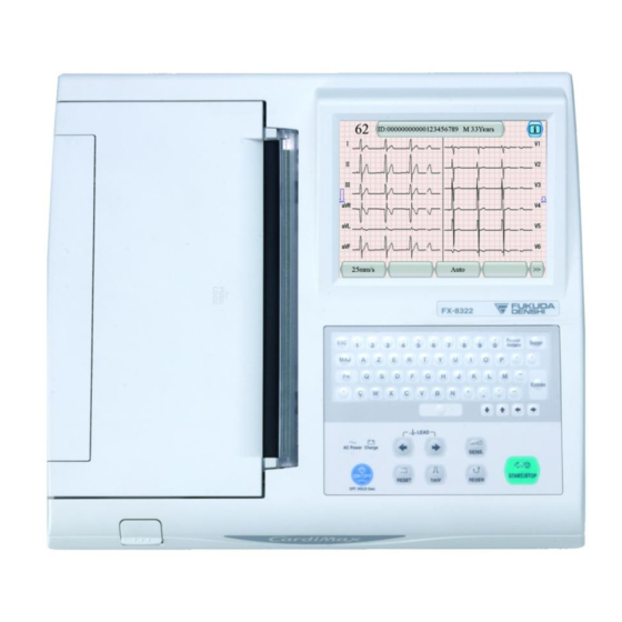
General-purpose ECG
C
a
r
d
i
M
C
a
r
d
i
M
● Read this service manual carefully before installing or performing maintenance of the
equipment.
● After reading, keep this manual near the equipment for future use.
a
x
F
X
-
8
a
x
F
X
-
8
●
Service Manual
3
2
2
/
F
X
-
3
2
2
/
F
X
-
8
3
2
2
R
8
3
2
2
R
Advertisement
Table of Contents

Related Manuals for Fukuda Denshi CardiMax FX-8322


Summary of Contents for Fukuda Denshi CardiMax FX-8322
- Page 1 General-purpose ECG ● Service Manual ● Read this service manual carefully before installing or performing maintenance of the equipment. ● After reading, keep this manual near the equipment for future use.
- Page 2 If you have any comment or request on usability, viewability, readability, or if you notice anything hard to understand on this service manual, please inform it to us. Development & Production Support Dept. Fukuda Denshi Co., Ltd. 2-35-8 Hongo Bunkyo-ku, Tokyo 113-8420 Japan Received by...
- Page 3 Revision History Model name FX-8322/FX-8322R Service Manual Revision History Item Reason Revision date Version Initial Version February, 2010...
- Page 5 Introduction This manual provides technical information on "CardiMax FX-8322/FX-8322R" (hereafter referred to as "FX-8322/FX-8322R") for Fukuda Denshi service personnel and authorized engineers. Before performing maintenance or troubleshooting on the equipment, read the manual carefully in order to use it correctly and safely.
- Page 6 Safety Precautions Indication of warning items: The following warning items indicate the extent of injury or damage that may result from incorrect handling of the equipment not observing the warning precautions. Failure to follow these instructions could cause death, serious DANGER injury, or imminent danger of fire.
- Page 7 Otherwise, the safety of FX-8322/FX-8322R cannot be ensured and the patient or the operator may be exposed to dangerous situation. CAUTION This service manual is intended for use by authorized Fukuda Denshi service personnel and technicians trained in medical electronic equipment. Use proper facilities and tools when repairing and/or assembling the FX-8322/FX-8322R.
- Page 8 ● Danger of Explosion DANGER Do not operate the FX-8322/FX-8322R in an atmosphere of flammable anesthetic gas or oxygen in high concentration. Explosion or fire may result. Do not operate the FX-8322/FX-8322R within a hyperbaric oxygenation tank. Explosion or fire may result. Do not operate the FX-8322/FX-8322R in a place where flammable liquids or gases such as anesthetics, oxygen, and hydrogen are used.
- Page 9 ● Specified items WARNING Make sure to only use accessories and option items that are specified for the FX-8322/FX-8322R. Use of non-specified products may lead to inferior performance of the equipment, including the possibilities of injury to the patient and operator as well as failure of the equipment.
- Page 10 ● About Maintenance and Callibration WARNING If, during a safety inspection, a value that exceeds the allowable limit is confirmed, immediately stop using the FX-8322/FX-8322R; then replace the defective part or make proper repairs. Failure to repair the unit can lead to a serious accident. CAUTION Note that we are not responsible for accidents caused by not performing maintenance and inspection.
- Page 11 Overview of the Manual The manual is intended for Fukuda Denshi service personnel and authorized engineers. This service manual provides technical information on CardiMax FX-8322/FX-8322R. It has been prepared for troubleshooting and repairing the equipment. It contains the parts and assembly drawings of the FX-8322/FX-8322R, as well as descriptions to help you understand the operating principles of the equipment.
-
Page 12: Table Of Contents
Contents 1 Overview ............................... 1-1 2 Specifications ............................2-1 2-1 Safety ............................2-1 2-2 Power Supply ..........................2-1 2-3 Cardioverter..........................2-1 2-4 Functional Specifications ......................2-1 2-5 Environmental Conditions......................2-2 2-6 Outside Dimensions/Weight ...................... 2-2 2-7 Guidance for EMC........................2-3 2-7-1 Compliance with Electromagnetic Emissions ............... - Page 13 5 Internal Connection Diagram ......................5-1 6 Spare Parts List ............................ 6-1 7 Disassembly and Assembly Procedure....................7-1 7-1 Upper Case Block (1/2) ......................7-1 7-2 Upper Case Block (2/2) ......................7-2 7-3 Lower Case Block (1/4) ......................7-3 7-4 Lower Case Block (2/4) ......................7-4 7-5 Lower Case Block (3/4) ......................
- Page 14 11-2 Cleaning ..........................11-2 11-3 Replacing On-board Parts ......................11-3 11-3-1 Removing the CPU BOARD (PCB-7285)..............11-4 11-3-1-1 Removing the Battery..................11-4 11-3-1-2 Removing the Upper and Lower Cases ............11-5 11-3-1-3 Removing Cables, Screws and Panels ............11-6 11-3-1-4 Removing CRT BOARD ................11-6 11-3-1-5 Removing CPU BOARD................11-7 11-3-2 Removing the OPERATION BOARD (PCB-7359) .............11-8 11-3-3 Removing the LCD Module..................11-9 11-3-4 Removing the ECG AMP BOARD (PCB-6731) ............11-10...
- Page 15 12-3-5-7 Mac Address ....................12-18 12-3-5-8 Log Output ....................12-19 12-3-5-9 Factory Default Setting ................12-20 12-3-5-10 Install......................12-21 12-3-5-11 Uninstall ....................12-22...
- Page 17 Chapter 1 Overview Overview 1 Overview ...........................1-1...
- Page 18 Chapter 1 Overview...
-
Page 19: Overview
Chapter 1 Overview 1 Overview The FX-8322/FX-8322R is a general purpose ECG that can be used for screening heart diseases as well as for general ECG examinations, by performing ECG examinations with a minimum of 12 leads including limb and chest leads and recording ECG data and their measurement results in health clinics and hospitals. For the FX-8322R, external monitor can be connected. - Page 20 Chapter 1 Overview...
- Page 21 Chapter 2 Specifications Specifications 2 Specifications ........................2-1 2-1 Safety ........................2-1 2-2 Power Supply .......................2-1 2-3 Cardioverter......................2-1 2-4 Functional Specifications..................2-1 2-5 Environmental Conditions..................2-2 2-6 Outside Dimensions/Weight .................2-2 2-7 Guidance for EMC....................2-3 2-7-1 Compliance with Electromagnetic Emissions........2-3 2-7-2 Compliance with Electromagnetic Immunity (1) ........2-3 2-7-3 Compliance with Electromagnetic Immunity (2) ........2-4 2-7-4...
- Page 22 Chapter 2 Specifications...
-
Page 23: Specifications
Chapter 2 Specifications 2 Specifications 2-1 Safety Protection against electric shock Internally-powered equipment; CF type attachment 2-2 Power Supply AC power 100 – 240V AC 50/60Hz DC power 14.8V DC (when optional battery is used) Power consumption (AC) 100VA (AC), 80W (DC) 12V power supply for vehicles Unavailable 2-3 Cardioverter... -
Page 24: Environmental Conditions
Chapter 2 Specifications OP-618TE Built-in Type Roll Paper 30M OP-621TE External Type Roll Paper (Backside patient’s chart 100M) OP-621TEU-5 External Type Roll Paper (Thin: 100M) OP-621TE300M-U External Type Roll Paper (Thin: 300M) OP-622TE External Type Roll Paper (Backside patient’s chart: White paper 100M) OP-623TE External Type Roll Paper (Thin: White paper 100M) -
Page 25: Guidance For Emc
Chapter 2 Specifications 2-7 Guidance for EMC 2-7-1 Compliance with Electromagnetic Emissions This equipment is intended for use in the electromagnetic environment specified in the following table. Before using the FX-8322/FX-8322R, check the environment of the site where it is used. Emission test Compliance Electromagnetic environment/guidance... -
Page 26: Compliance With Electromagnetic Immunity (2)
Chapter 2 Specifications 2-7-3 Compliance with Electromagnetic Immunity (2) The FX-8322/FX-8322R is intended for use in the electromagnetic environment specified in the following table. IEC 60601 Compliance Immunity test Electromagnetic environment/guidance Test level level Do not use portable or mobile RF communications equipment in a place closer to any part of the FX-8322/FX-8322R (including cables) than the recommended separation distance... -
Page 27: Recommended Separation Distance Between Portable/Mobile Rf Communications Equipment And The Fx-8322
Chapter 2 Specifications 2-7-4 Recommended Separation Distance between Portable/Mobile RF Communications Equipment and the FX-8322/FX-8322R This equipment is intended for use in an electromagnetic environment where RF emission interference is controlled. The electromagnetic interference can be prevented during operation by controlling the minimum distance between the portable/mobile RF communications equipment (transmitters) and this equipment shown below (recommended values based on the maximum output power of the transmitter). - Page 28 Chapter 2 Specifications...
- Page 29 Chapter 3 Names and Functions of Parts Names and Functions of Parts 3 Names and Functions of Parts ..................3-1 3-1 Outside Drawing of the Equipment ...............3-1 3-2 Names and Descriptions of Parts .................3-2...
- Page 30 Chapter 3 Names and Functions of Parts...
-
Page 31: Names And Functions Of Parts
Chapter 3 Names and Functions of Parts 3 Names and Functions of Parts 3-1 Outside Drawing of the Equipment (7) Paper tray (20) Upper housing (8) Thermal head (5) LCD (3) AC lamp (Blue) (6) Touch key (19) R-wave synchronized signal (17) Paper tray open button (10) USB ports 1-2... -
Page 32: Names And Descriptions Of Parts
Chapter 3 Names and Functions of Parts 3-2 Names and Descriptions of Parts Operation panel [Start]/[Stop] key Starts/stops recording. [Review] key Starts recording the ECG waveform 10 seconds earlier. [Reset] key Resets the input waveform. [1mV] key Inserts a calibration wave. [Lead ] and [Lead ] keys... - Page 33 Chapter 4 Operational Description Operational Description 4 Operational Description.....................4-1 4-1 Hardware Overview....................4-1 4-2 System Block Diagram ..................4-2 4-3 Operational Description ..................4-3 4-3-1 Primary Power Supply Unit ..............4-3 4-3-2 CPU Board Section................4-4 4-3-2-1 Secondary Power Supply Unit ..........4-4 4-3-2-2 Bus I/F ..................4-6 4-3-2-3 Thermal Head Control Section ..........4-6 4-3-2-4...
- Page 34 Chapter 4 Operational Description...
-
Page 35: Operational Description
Chapter 4 Operational Description 4 Operational Description 4-1 Hardware Overview ECG waveforms from the patient are printed on recording paper. High-precision color LCD displays highly detailed ECG data. The general configuration diagram of the FX-8322/FX-8322R, including optional configurations, is shown below. -
Page 36: System Block Diagram
Chapter 4 Operational Description 4-2 System Block Diagram The internal block diagram and general specifications of FX-8322/FX-8322R body unit are shown below. The following describes the blocks in bold. AC IN Speaker SD CARD RS-232C R-SYNC CRT Board Section (FX-8322R) Battery Primary Power CPU Board Section &... -
Page 37: Operational Description
Chapter 4 Operational Description 4-3 Operational Description 4-3-1 Primary Power Supply Unit The functional block diagram of the primary power supply unit is shown below. AC90 ~ 264V +18V Inrush Current 47 ~ 63Hz Prevention +18V Circuit Generation Fuse Unit Line Filter Fuse Switching... -
Page 38: Cpu Board Section
Chapter 4 Operational Description 4-3-2 CPU Board Section 4-3-2-1 Secondary Power Supply Unit The block diagram regarding the secondary power supply circuit is shown below. Primary power 18V DC supply input Battery input 14.8V DC Battery +3.3V +3.0V DC-DC1 DC-DC DC-DC +1.8V Power Supply... - Page 39 Chapter 4 Operational Description The secondary power supply circuit performs the following operations. Charge control: Controls and manages the charging of the lithium-ion secondary battery. The battery is charged only when the temperature is within the specified range; and charging will be aborted, even while charging is in progress, if any abnormal temperature is detected.
-
Page 40: Bus I/F
Chapter 4 Operational Description 4-3-2-2 Bus I/F The block diagram regarding the bus I/F is shown below. 32-bit bus SDRAM 16-bit bus FPGA LAN Ctrl FLASH ROM The FPGA, LAN controller and FLASH ROM are connected to the MAIN BUS. The MAIN BUS has a bus width of 16 bits. -
Page 41: Motor Drive Section
Chapter 4 Operational Description 4-3-2-4 Motor Drive Section The block diagram of the motor drive section is shown below. PCB-7285 Feeding rate data Motor driver Motor drive pulse drive signal Stepping FPGA Motor Driver Motor Motor Driver Secondary power supply Power Supply The motor is controlled as follows. -
Page 42: Sensor Drive Section
Chapter 4 Operational Description 4-3-2-5 Sensor Drive Section The block diagram of the sensor drive section is shown below. Threshold Detected Amplify signal Compare FPGA Buffer Photo Transistor Sensor drive Sensor output pulse Paper The paper end sensor and mark sensor are controlled as follows. The sensor drive pulse output from the FPGA is input to the phototransistor via a buffer. -
Page 43: Sd Card I/F Section
Chapter 4 Operational Description 4-3-2-7 SD CARD I/F Section The block diagram regarding the SD CARD I/F is shown below. SD Card Slot A CPU-integrated SD card controller is used to transfer various commands and data. To prevent inrush current, it incorporates a FET that does not supply power unless an SD card is inserted. 4-3-2-8 RS-232C I/F Section The block diagram regarding the RS-232C I/F is shown below. -
Page 44: R-Sync I/F Section
Chapter 4 Operational Description 4-3-2-10 R-Sync I/F Section The block diagram of R-Sync I/F is shown below. R-Sync FPGA Connector Outputs High (+5V), Low (0V) signals synchronized to the R-Sync output. 4-3-3 ECG Amp Board Section The functional block diagram of the ECG input section is shown below. PCB-6731 Input Differential... -
Page 45: Operation Board Section
Chapter 4 Operational Description 4-3-4 Operation Board Section The block diagram of the operation board is shown below. Touch panel control Power signal supply Touch Panel Connects to touch panel Controller Coordinate data Coordinates BL_SIG Transformer Inverter power supply Connects to Connects to LCD inverter CPU BOARD... -
Page 46: Crt Board Section
Chapter 4 Operational Description 4-3-5 CRT Board Section SDRAM BOARD AX51901 (AG-9) External Monitor AD813 The CPU BOARD outputs the signal for the external monitor via the AG-9 (digital RGB) and DAC (analog RGB). 4-12... -
Page 47: Internal Connection Diagram
Chapter 5 Internal Connection Diagram Internal Connection Diagram 5 Internal Connection Diagram.....................5-1... - Page 48 Chapter 5 Internal Connection Diagram...
- Page 49 Chapter 5 Internal Connection Diagram 5 Internal Connection Diagram Internal connection diagram of the FX-8322/FX-8322R is shown below. PRIMARY PWR TRAY UP SENSOR TRAY UP SENS CAUTION Connectors and cables should be repaired by either replacing the connector/cable or requesting the factory to perform the repair. Connectors used on the boards are very small and have extremely fine pin pitches.
- Page 50 Chapter 5 Internal Connection Diagram...
- Page 51 Chapter 6 Spare Parts List Spare Parts List 6 Spare Parts List.........................6-1...
- Page 52 Chapter 6 Spare Parts List...
-
Page 53: Spare Parts List
Chapter 6 Spare Parts List 6 Spare Parts List The replacement spare parts list is shown below. Part No. Part name Description Q'ty 1T0100600 Power supply unit APAV003-07 1L0100540 LTA065B0D0F 1G0100310 Touch panel FD-42-1D 1W003042B Thermal head AE216-8E603 1Y0100100 Motor PJP28T51G14-01 1G0100370 Membrane Key... - Page 54 Chapter 6 Spare Parts List Part No. Part name Description Q'ty 1Z0101210 Gasket E02S100100RT 35mm 5H0103620 Caution label 9H0102780 Lower case SU 6C0115290 Battery cover 1K0018000 Potential equalization terminal POAG-S6/15 6C0035190 Rubber Support 6C0115300 Main Unit Chassis 6C0115310 Potential equalization terminal Cover 6C0115320 Insulation sheet (capacitor) 6C0117240...
- Page 55 Chapter 6 Spare Parts List Part No. Part name Description Q'ty 9H0102540 Paper support plate B(SU) 6C0113350 Ultra Spring C-144 6C0115090 Paper case side plate 6C0112850 Sensor button 6C0113180 Ultra Spring E-538 6C0115100 Hook 6C0115110 Hook mounting shaft 9H0103170 Platen roll guide plate SU 9H0102750 Thermal head fixing plate SU 6C0090710...
- Page 56 Chapter 6 Spare Parts List...
- Page 57 Chapter 7 Disassembly and Assembly Procedure Disassembly and Assembly Procedure 7 Disassembly and Assembly Procedure ................7-1 7-1 Upper Case Block (1/2) ..................7-1 7-2 Upper Case Block (2/2) ..................7-2 7-3 Lower Case Block (1/4) ..................7-3 7-4 Lower Case Block (2/4) ..................7-4 7-5 Lower Case Block (3/4) ..................7-5 7-6 Lower Case Block (4/4) ..................7-6 7-7 Recorder Block (1/8) ....................7-7...
-
Page 58: Disassembly And Assembly Procedure
Chapter 7 Disassembly and Assembly Procedure... -
Page 59: Disassembly And Assembly Procedure
Chapter 7 Disassembly and Assembly Procedure 7 Disassembly and Assembly Procedure 7-1 Upper Case Block (1/2) Cable color: white *Place the white cable inside when attaching. ® 2-Kapton No.5419 View A 1M0101670 310-13532 FCP-8221 Backlight Relay Cable 1M0101650 310-13531 LCD Cable (30P) Same with FCP-8221 1M0102240 Cable... -
Page 60: Upper Case Block (2/2)
Chapter 7 Disassembly and Assembly Procedure 7-2 Upper Case Block (2/2) Gasket Attachment Position (View A) 4-Double sided tape NITTO No.541 Width 5mm *Attachment position for the double sided tape: Middle for upper/lower tape, downward for left/right tape. Align end face 1Z0101210 Gasket (E02S100100RT) 1G0100310... -
Page 61: Lower Case Block (1/4)
Chapter 7 Disassembly and Assembly Procedure 7-3 Lower Case Block (1/4) 5-Washer-based P tight screw M3 × 10 View A 7-W sems (L) M3 × 8 3-W sems (L) M2 × 6 Align with on-board contact 3-W sems (L) M2 × 6 when attaching. -
Page 62: Lower Case Block (2/4)
Chapter 7 Disassembly and Assembly Procedure 7-4 Lower Case Block (2/4) 2-Nut (3) M6 2-W sems (S) M3 × 14 6C0117240 310-14352 Insulation Sheet (Power Source Coil) 6C0115320 310-14035 Insulation Sheet (Capacitor) 5H0056010 154-3568 In-panel Earth Mark Same with FX-326U 1M0102250 310-14346 FCP-8321 AC Inlet Cable... -
Page 63: Lower Case Block (3/4)
Chapter 7 Disassembly and Assembly Procedure 7-5 Lower Case Block (3/4) 6-Washer-based P tight screw M3 × 10 5H010540A 310-14354 Caution Label (Battery) 9E0108570 310-14348 Speaker ASSY 410-4262 ECG Amplifier Assembly Drawing 6C0035190 314-5082 Rubber Support Same with FCP-7411 6C0115290 310-14032 Battery Cover 6C0102050... -
Page 64: Lower Case Block (4/4)
Chapter 7 Disassembly and Assembly Procedure 7-6 Lower Case Block (4/4) 1T0100520 Ferrite Core FPC-11-8-2 Same with FCP-8221 2-Washer-based P tight screw M3 × 10 1M0101690 Cable Same with FCP-8221 9F0054980 PCB-6699A ASSY Same with FCP-7411 6C0113270 310-13711 ECG shield plate Same with FCP-8221 5G0010630 114-7128... -
Page 65: Recorder Block (1/8)
Chapter 7 Disassembly and Assembly Procedure 7-7 Recorder Block (1/8) ® 3-Kapton No.5419 Tape Attachment Position 1Z0101230 Finger Strips (E01S24) 6C0115240 310-14025 Tray Axis Shaft 410-4250 Tray Assembly Drawing 410-4254 Recorder Assembly Drawing 2-E ring Nominal diameter 4 Item no. Drawing no. -
Page 66: Recorder Block (2/8)
Chapter 7 Disassembly and Assembly Procedure 7-8 Recorder Block (2/8) Attach between ○ mark. Apply grease to outer circumference of the collar tip. Grease (MOLYKOTE EM-30L Dow Corning Asia Ltd.) Align the end face. Tape Brush Attachment Position Caution) Pay attention not to have the grease attached to the spring retainer color and tray support springs. -
Page 67: Recorder Block (3/8)
Chapter 7 Disassembly and Assembly Procedure 7-9 Recorder Block (3/8) Sensor ASSY Connection 6C0115170 Ultra Spring C-219 6C0034980 314-5063 Thermal Head Support Plate Same with FCP-7411 6C0115190 310-14019 Hook Spring 6C0115180 310-14018 Tray Lever 6C0115090 310-14009 Paper Case Side Plate 410-4253 Paper Case Assembly Diagram 410-4252... -
Page 68: Recorder Block (4/8)
Chapter 7 Disassembly and Assembly Procedure 7-10 Recorder Block (4/8) 2 W sems (S) M2 × 10 9E0108580 310-14350 Sensor ASSY 6C0113180 Ultra Spring E-538 Same with FCP-8221 6C0113350 Ultra Spring C-144 Same with FCP-8221 6C0115100 310-14010 Hook 6C0115110 310-14011 Hook Mounting Shaft 6C0112850 310-13668... -
Page 69: Recorder Block (5/8)
Chapter 7 Disassembly and Assembly Procedure 7-11 Recorder Block (5/8) 2 Hexagon socket head cap screw M3x8 2 Pan-Head Screw M3x5 1L0045020 Ferrite Core (ZCAT1325-0530A) 2-E ring Nominal diameter 4 1M008900 680-3758 Thermal Cable Same with FCP-7411 6C0090700 310-7973 Thermal Head Fixing Shaft Same with FCP-7301 6C0036500 314-5312... -
Page 70: Recorder Block (6/8)
Chapter 7 Disassembly and Assembly Procedure 7-12 Recorder Block (6/8) 2-E ring Nominal diameter 4 6C0035060 314-5071 Platen Roll Collar Same with FCP-7411 6C0115030 310-14002 Gear B 6C0096930 Bearing DDL-1060ZZ-LY551 Same with FCP-7411 6C0115010 310-14000 Platen Roll 6C0036500 314-5312 Static Electricity Elimination Felt A Same with FCP-7411 6C003478A 312-5036... -
Page 71: Recorder Block (7/8)
Chapter 7 Disassembly and Assembly Procedure 7-13 Recorder Block (7/8) 2-W sems (L) M3 × 8 6C0115160 310-14017 Paper Cutter 6C0115150 310-14016 Recorder Chassis Item no. Drawing no. Name/Type Qty. Note 7-13... -
Page 72: Recorder Block (8/8)
Chapter 7 Disassembly and Assembly Procedure 7-14 Recorder Block (8/8) E ring Nominal diameter 3 Apply grease to the shaft part (3 parts). Grease (MOLYKOTE EM-30L Dow Corning Asia Ltd.) 3 Pan-Head Screw M2.6 × 8 4-W sems (L) M2.5 × 16 1M0101710 310-13537 CPU - Motor cable (4P) -
Page 73: Crt Block (For Fx-8322R)
Chapter 7 Disassembly and Assembly Procedure 7-15 CRT Block (For FX-8322R) Note) After fixing the inch screw, apply screw lock from back. 1Z0101220 Gasket (E02S100040RT) 6C0117280 310-14358 Main Unit Shield Plate (C) 1Z0101240 Finger Strips (E01C11) 6 tabs 5T0035420 Inch Screw XM4Z-0023 Same with FCP-7411 6C0115360 310-14039... -
Page 74: General Assembly Drawing
Chapter 7 Disassembly and Assembly Procedure 7-16 General Assembly Drawing ® Kapton No.5419 8-Washer-based P tight screw M3 × 10 Attach above ○ mark. 6-W sems (L) M3 × 8 3-W sems (L) M2 × 6 9E0108100 Rated Label (Numbered) 5H0105040 310-14137 Model Type Label (FX-8322) -
Page 75: Outside Drawing
Chapter 7 Disassembly and Assembly Procedure 7-17 Outside Drawing 7-17... - Page 76 Chapter 7 Disassembly and Assembly Procedure 7-18...
-
Page 77: Software Update Procedure
Chapter 8 Software Update Procedure Software Update Procedure 8 Software Update Procedure ....................8-1... - Page 78 Chapter 8 Software Update Procedure...
- Page 79 Chapter 8 Software Update Procedure 8 Software Update Procedure The following pages describe the software update procedure. CAUTION Never remove the SD card while software update is in progress. It may lead to failure of the equipment and/or the SD card; or it may become impossible to perform software update.
- Page 80 Chapter 8 Software Update Procedure Insert the SD card containing the software into the SD card slot of the FX-8322/FX-8322R. (2) Insert the AC cable into the equipment and press the [Power] key while holding down the lead switch [←] key. [Power] key [←] key * Be sure to hold down the [←] key until the install screen is displayed.
-
Page 81: Caution Labels
Chapter 9 Caution Labels Caution Labels 9 Caution Labels ........................9-1... - Page 82 Chapter 9 Caution Labels...
- Page 83 Chapter 9 Caution Labels 9 Caution Labels The following shows the attachment positions of the danger/warning labels. CAUTION The danger/warning/caution labels attached on the FX-8322/FX-8322R provide important information for using the FX-8322/FX-8322R safely and properly. Do not damage or erase characters on the labels.
- Page 84 Chapter 9 Caution Labels...
- Page 85 Chapter 10 Troubleshooting Troubleshooting 10 Troubleshooting......................10-1 10-1 Repair and Service ...................10-1 10-1-1 When ECG Recording is Unstable ............10-1 10-1-2 When the Equipment Does Not Operate Normally......10-2 10-2 When Error Message is Displayed ..............10-3 10-3 Hardware Troubles ...................10-5 10-3-1 Trouble On Start-up................10-6 10-3-2 Trouble During Operation..............10-7 10-3-2-1...
- Page 86 Chapter 10 Troubleshooting...
-
Page 87: Troubleshooting
Chapter 10 Troubleshooting 10 Troubleshooting 10-1 Repair and Service 10-1-1 When ECG Recording is Unstable In the event when ECG recording is unstable, try operating the equipment again after checking the following items. Is the examination location appropriate? ☞ Is there a noise source near the FX-8322/FX-8322R such as x-ray imaging equipment, ultrasound imaging equipment, mobile phone, microwave oven, microwave therapy equipment or other electrical devices? If there is, either turn off the power of the device or operate the FX-8322/FX-8322R at a different... -
Page 88: When The Equipment Does Not Operate Normally
Chapter 10 Troubleshooting 10-1-2 When the Equipment Does Not Operate Normally In the event when the FX-8322/FX-8322R fails to operate, try operating the equipment again after checking the following items. Is the AC power supply in good condition? ☞ Is the 100–240V AC commercial power being supplied? ☞... -
Page 89: When An Error Message Is Displayed
Chapter 10 Troubleshooting 10-2 When an Error Message is Displayed During operation, the FX-8322/FX-8322R displays various messages that seeks the user's confirmation. Refer to the [FX-8322/FX-8322R Operation Manual] for details of each message. This section describes the causes and remedies for important messages. Messages regarding the battery (not battery fault) Message Cause/Remedy... - Page 90 Chapter 10 Troubleshooting Messages regarding different media cards Message Cause/Remedy • [Cause] SD card formatting has failed. SD card formatting failed. [Remedy] The inserted SD card may be defective. [Cause] There is no free space in the SD card. • There is no free space in the SD card.
-
Page 91: Hardware Troubles
Chapter 10 Troubleshooting 10-3 Hardware Troubles WARNING Do not unplug the AC power supply or remove the battery abruptly during operation. Make sure to shut down the equipment using the power switch. It could otherwise result in irreparable damage to the system files. CAUTION If any electrical parts need to be replaced, it is recommended to replace the entire board whenever possible. -
Page 92: Trouble On Start-Up
Chapter 10 Troubleshooting 10-3-1 Trouble On Start-up Symptom Cause Trouble location Remedy • • AC standby power Replace power • Power cable not supplied cable • • Failure of AC power Replace operation • Operation panel supply LED panel • The AC power supply •... -
Page 93: Trouble During Operation
Chapter 10 Troubleshooting 10-3-2 Trouble During Operation 10-3-2-1 Symptom Cause Trouble location Remedy • CPU BOARD • • Failure of FPGA Replace PCB-7285 FPGA peripheral circuit • ECG continues being • • Failure of ECG Amp ECG Amp power supply displayed as a baseline. -
Page 94: Lcd
Chapter 10 Troubleshooting 10-3-2-2 Symptom Cause Trouble location Remedy • ASCUJ(0.5)-40F-200-7S3(B)- M1(20624) • • Replace cable Backlight power not • FCP-8221 backlight relay • supplied Replace LCD cable • LCD inverter cable • • Failure of inverter Inverter power supply circuit •... -
Page 95: Recording And Recorders
Chapter 10 Troubleshooting 10-3-2-3 Recording and Recorders Symptom Cause Trouble location Remedy • Break in cable or cable • • Thermal cable Replace thermal head not plugged in properly • Nothing is printed. • • • Failure of FPGA FPGA Replace PCB-7285 •... -
Page 96: Other
Chapter 10 Troubleshooting 10-3-2-5 Other Symptom Cause Trouble location Remedy • No sound is heard from the • • • Failure of speaker Speaker Replace speaker speaker. • • • Failure of speaker circuit Speaker circuit Replace PCB-7285 (or no sound is played) •... -
Page 97: Maintenance
Chapter 11 Maintenance Maintenance 11 Maintenance........................11-1 11-1 Notes on Maintenance..................11-1 11-2 Cleaning ......................11-2 11-3 Replacing On-board Parts ................11-3 11-3-1 Removing the CPU BOARD (PCB-7285)..........11-4 11-3-1-1 Removing the Battery ............11-4 11-3-1-2 Removing the Upper and Lower Cases......... 11-5 11-3-1-3 Removing Cables, Screws and Panels........ - Page 98 Chapter 11 Maintenance...
-
Page 99: Notes On Maintenance
Chapter 11 Maintenance 11 Maintenance 11-1 Notes on Maintenance Make sure to observe the following cautions when performing maintenance of the equipment. CAUTION Note that we may not be responsible for any accidents resulting from your negligence in failing to perform maintenance and inspection. Make sure to carry out daily check before using the equipment. -
Page 100: Cleaning
Chapter 11 Maintenance 11-2 Cleaning Be sure to perform cleaning while the equipment is turned off. Read the [FX-8322/FX-8322R Operation Manual] for instructions on turning the equipment on and off. Regularly wipe the surface of the FX-8322/FX-8322R with a dry cleaning cloth. To remove stubborn dirt, moisten the cloth with ethanol or water, squeeze the cloth firmly, and then wipe off the dirt with it. -
Page 101: Replacing On-Board Parts
When replacing parts, make sure to only use parts that are specified for the equipment. Use proper screwdrivers to tighten or loosen screws. Make sure to use screws that are specified by Fukuda Denshi. When reassembling, make sure all screws are tightened to original positions and all disconnected connectors are reconnected properly. After assembling the equipment, check that there are no foreign objects in the connector sockets or in the battery terminal. -
Page 102: Removing The Cpu Board (Pcb-7285)
Chapter 11 Maintenance 11-3-1 Removing the CPU BOARD (PCB-7285) 11-3-1-1 Removing the Battery * This procedure can be ignored if no battery is installed in the equipment. 1. Turn the equipment upside down, remove two W sems (L) M3 × 8, and remove the battery cover. 2. -
Page 103: Removing The Upper And Lower Cases
Chapter 11 Maintenance 11-3-1-2 Removing the Upper and Lower Cases * If a battery is installed in the equipment, it should be removed before disassembling the equipment. 1. Remove seven W sems (L) M3 x 10. 2. Open the upper case in the direction of the arrow. 11-5... -
Page 104: Removing Cables, Screws And Panels
Chapter 11 Maintenance 11-3-1-3 Removing Cables, Screws and Panels 1. Disconnect the 9 cables connected to the CPU BOARD (PCB-7285). 2. Remove two tapping screws and four W sems (L) M3 x 8 ,and then remove the side panel, rear panel and main unit plate. -
Page 105: Removing Cpu Board
Chapter 11 Maintenance 11-3-1-5 Removing CPU BOARD 1. Remove one tapping screw, one W-sems (L) M3 x 8 and disconnect the fan cable. 2. Disconnect the battery connection cable. 3. Remove the CPU BOARD (PCB-7285). 11-7... -
Page 106: Removing The Operation Board (Pcb-7359)
Chapter 11 Maintenance 11-3-2 Removing the OPERATION BOARD (PCB-7359) 1. Remove the upper case as shown in "Removing the Upper and Lower Cases". 2. Disconnect the 4 cables connected to the PCB-7359. 3. Remove four tapping screws, and then remove the OPERATION BOARD (PCB-7359). 11-8... -
Page 107: Removing The Lcd Module
Chapter 11 Maintenance 11-3-3 Removing the LCD Module 1. Disconnect the LCD cable connected to the LCD module. 2. Remove four tapping screws, and then remove the LCD module plate and LCD module. 11-9... -
Page 108: Removing The Ecg Amp Board (Pcb-6731)
Chapter 11 Maintenance 11-3-4 Removing the ECG AMP BOARD (PCB-6731) 11-3-4-1 Removing the Upper and Lower Cases See "11-3-1-2 Removing the Upper and Lower Cases". 11-3-4-2 Removing Cables, Screws and Panels See "11-3-1-3 Removing Cables, Screws and Panels". 11-3-4-3 Removing the Recorder Unit 1. -
Page 109: Removing The Power Supply Unit
Chapter 11 Maintenance 11-3-4-4 Removing the Power Supply Unit 1. Remove four tapping screws, and then remove the main unit shield B and power supply unit. 11-11... -
Page 110: Removing The Ecg Amp Board (With Case)
Chapter 11 Maintenance 11-3-4-5 Removing the ECG AMP BOARD (with case) 1. Remove four tapping screws, and remove the ECG AMP BOARD with the case intact. 11-3-4-6 Removing the ECG AMP Board 1. Remove two tapping screws, and then remove the ECG AMP BOARD. 11-12... -
Page 111: Safety Block Diagram
Chapter 11 Maintenance 11-4 Safety Block Diagram The safety block diagram is shown on the next page. It can be used as a reference when performing maintenance of the equipment. 11-13... - Page 112 Chapter 11 Maintenance Plastic (Resin) Enclosure Surface [Insulation] *3 Interim circuit (1) Basic insulation Operation Thermal head (Secondary circuit) panel (between A-a1) (2) Reinforced insulation (between R-sync connector Electrode/ A-a2) Lead cable (3) Reinforced External monitor input insulation (between connector circuit B-a) (4) Basic insulation...
-
Page 113: Daily And Periodic Checks
Chapter 12 Daily and Periodic Checks Daily and Periodic Checks 12 Daily and Periodic Checks ....................12-1 12-1 Cautions on Maintenance and Inspection ............12-1 12-2 Daily Check ......................12-2 12-2-1 Visual Check ..................12-3 12-2-2 Mechanical Check................12-3 12-2-3 Electrical Check ..................12-3 12-3 Periodic Check ....................12-4 12-3-1 Safety Check (6 items)................12-5 12-3-1-1... - Page 114 Chapter 12 Daily and Periodic Checks...
-
Page 115: Cautions On Maintenance And Inspection
Chapter 12 Daily and Periodic Checks 12 Daily and Periodic Checks 12-1 Cautions on Maintenance and Inspection In order to assure safety, performance and reliability of the equipment, make sure to perform "daily check" and "periodic check" as designated. Make sure to clean the FX-8322/FX-8322R before and after the check. To remove stubborn dirt, moisten the cloth with neutral detergent, squeeze the cloth firmly, wipe off the dirt with it and then wipe again thoroughly with dry cloth. -
Page 116: Daily Check
Chapter 12 Daily and Periodic Checks 12-2 Daily Check Make sure to carry out the daily check according to the instructions in this chapter. [Daily Check List] is included at the end of the chapter. If any result in the daily check sheet is "No good", the overall judgment is "No good". -
Page 117: Visual Check
Chapter 12 Daily and Periodic Checks 12-2-1 Visual Check Visually check the equipment according to the following table. Item Check item Check procedure Judgment criterion External Free from outer scratches, Check the appearance of the main unit. appearance cracks, deformation and rust. Main unit Nameplate Check that they are visible and... -
Page 118: Periodic Check
Chapter 12 Daily and Periodic Checks 12-3 Periodic Check The periodic check may be performed by your institution, be entrusted to our service representative, or performed by an agent upon concluding a "Maintenance and check contract". [Periodic Check List] and [Periodic Check List (Safety check)] are included at the end of the chapter. If any result in the periodic check sheet is "No good", the overall judgment is "No good". -
Page 119: Safety Check (6 Items)
Chapter 12 Daily and Periodic Checks 12-3-1 Safety Check (6 items) In order to ensure safe handling of medical equipment and measuring instruments and to enable tests to be performed safely, leakage current and other factors that have adverse effect on human body are prescribed by the safety test standards. -
Page 120: Resistor Network
Chapter 12 Daily and Periodic Checks 12-3-1-1 Resistor Network Use a human-simulated resistor network such as shown below when measuring leakage current. Measurement Measurement (No leads) point A point B (No leads) Electronic voltmeter or digital voltmeter Leakage current is determined by measuring the voltages at both ends of the capacitor of the human-simulated resistor network (AC and DC) and then converting them into current values using the formula shown below. -
Page 121: Earth Leakage Current
Chapter 12 Daily and Periodic Checks 12-3-1-2 Earth Leakage Current Check the earth leakage current (current that flows to protective earth resistance). Acceptance standards Normal condition 0.5mA or less Single fault condition 1.0mA or less 12-3-1-3 Enclosure Leakage Current Check the enclosure leakage current (current that flows from the enclosure to the earth terminal of the power outlet). -
Page 122: Protective Earth Resistance
Chapter 12 Daily and Periodic Checks 12-3-1-7 Protective Earth Resistance Check the protective earth resistance. Acceptance standards 0.1 Ω or less Acceptance standards Between power supply cable protective earth terminal and 0.2 Ω or less potential equalization terminal 12-3-2 Visual check Visually check the equipment according to the following table. -
Page 123: Maintenance Test
Chapter 12 Daily and Periodic Checks 12-3-4 Maintenance Test The FX-8322/FX-8322R has the following manufacturer maintenance items. Refer to the [FX-8322/FX-8322R Operation Manual] for operations related to the maintenance test. Test item Check procedure Judgment criterion Check various equipment status can be Each status is displayed properly Status displayed. -
Page 124: Manufacturer Maintenance
Chapter 12 Daily and Periodic Checks 12-3-5 Manufacturer Maintenance The FX-8322/FX-8322R has the following manufacturer maintenance items. • AMP status • Board ID • Recorder test • Mac address • I/O test • Log output • Adjust touch panel • Factory settings •... - Page 125 Chapter 12 Daily and Periodic Checks Touch [Maintenance]. Touch [Manufacturer maintenance]. 12-11...
- Page 126 Chapter 12 Daily and Periodic Checks Enter "9001" in the password screen. Various manufacturer maintenance items will be displayed. On this screen (hereafter referred to as "manufacturer maintenance selection screen"), select the maintenance operations to be performed. The following pages describe the various maintenance procedures. 12-12...
-
Page 127: Amp Status
Chapter 12 Daily and Periodic Checks 12-3-5-1 AMP Status Select [AMP status] in the manufacturer maintenance selection screen shown below. The AD values that have been fetched from the ECG AMP BOARD are displayed. 12-13... -
Page 128: Recorder Test
Chapter 12 Daily and Periodic Checks 12-3-5-2 Recorder Test Select [Recorder test] in the manufacturer maintenance selection screen shown below. The recorder test is a test for checking the thermal head for missing dots as well as thermal head contact and uneven printing. When you select [Recorder test], the following screen is displayed. -
Page 129: I/O Test
Chapter 12 Daily and Periodic Checks 12-3-5-3 I/O Test Select [I/O test] in the manufacturer maintenance selection screen shown below. The I/O test is a test for checking the operation of each I/O. When you select [I/O test], the following screen is displayed. To perform the I/O test, the I/O to be tested needs to be set to the following state in advance. -
Page 130: Adjust Touch Panel
Chapter 12 Daily and Periodic Checks 12-3-5-4 Adjust Touch Panel Select [Adjust touch panel] in the manufacturer maintenance selection screen shown below, to adjust the coordinate positions of the touch panel. When you select [Adjust touch panel], the following screen is displayed. Following the on-screen instructions, touch the cross pointers using a touch-panel pen. -
Page 131: Keyboard Test
Chapter 12 Daily and Periodic Checks 12-3-5-5 Keyboard Test Select [Keyboard test] in the manufacturer maintenance selection screen shown below, to check the connection of an external keyboard. Connect the USB type keyboard to the USB port of the main unit, and check that the entered text is shown in the display. -
Page 132: Mac Address
Chapter 12 Daily and Periodic Checks 12-3-5-7 Mac Address Select [Mac address] in the manufacturer maintenance selection screen shown below, to enter the Mac address. When you select [Mac address], the following screen is displayed. Enter a specified Mac address and touch [Enter]. The Mac address will be saved. 12-18... -
Page 133: Log Output
Chapter 12 Daily and Periodic Checks 12-3-5-8 Log Output To save the operation log to an SD card, select [Log output] in the manufacturer maintenance selection screen shown below. When you select [Log output], the following screen is displayed. Insert an SD card in to the SD card slot and touch [Log output] to save the operation log in the SD card. 12-19... -
Page 134: Factory Default Setting
Chapter 12 Daily and Periodic Checks 12-3-5-9 Factory Default Setting To restore the settings to their factory default values, select [Factory settings] in the manufacturer maintenance selection screen shown below. When you select [Factory settings], the following screen is displayed. When you press the [Start/Stop] button, the equipment turns itself off automatically after restoring settings to their factory default values. -
Page 135: Install
Chapter 12 Daily and Periodic Checks 12-3-5-10 Install To install optional software, select [Installation] in the manufacturer maintenance selection screen shown below. When you select [Installation], the following screen is displayed. Insert the SD card, containing the optional software to be installed, into the SD card slot and touch [Installation] to start the installation of the optional software. -
Page 136: Uninstall
Chapter 12 Daily and Periodic Checks 12-3-5-11 Uninstall To uninstall optional software, select [Uninstallation] in the manufacturer maintenance selection screen shown below. When you select [Uninstallation], the following screen is displayed. Insert the SD card used for the installation into the SD card slot and touch [Uninstallation] to start the uninstallation of the optional software. - Page 137 Chapter 12 Daily and Periodic Checks Daily Check List Carry out the daily check according to the "Daily Check Procedure". Management No. Procedure and measurement/ Note Item Check item Judgment judgment criterion (Repair required) Exterior flaws, cracks, Check that flaws, cracks, deformation, and rust Good/ NG deformation, rust are not found on the main unit.
- Page 138 Chapter 12 Daily and Periodic Checks Periodic Check List (1) Carry out the periodic check according to "Periodic Check Procedure". Management No. Procedure and measurement/ Note Item Check item Judgment judgment criterion (Repair required) Exterior flaws, cracks, Check that flaws, cracks, deformation and rust Good/ NG deformation, rust are not found on the main unit.
- Page 139 Chapter 12 Daily and Periodic Checks Periodic Check Sheet (2) (Safety check) Carry out the periodic check according to "Periodic Check Procedure". Management No. Note Judgment Item Check content Measurement Judgment (Repair criterion required) Normal state 0.5mA or less Good/NG Earth leakage current •...
- Page 141 13 WESTMINSTER COURT, HIPLEY STREET OLD WOKING, SURREY GU22 9LG, U.K. Copyright © 2010 by Fukuda Denshi Co., Ltd. No part of this document may be copied or transmitted in any form without the prior written permission of Fukuda Denshi Co., Ltd.
- Page 142 39-4, Hongo 3-chome, Bunkyo-ku, Tokyo, Japan Phone:+81-3-3815-2121 Fax:+81-3-3814-1222 4R0100320 201003...
Need help?
Do you have a question about the CardiMax FX-8322 and is the answer not in the manual?
Questions and answers