Table of Contents
Advertisement
Quick Links
Advertisement
Table of Contents

Related Manuals for FLIR SV88-KIT


Summary of Contents for FLIR SV88-KIT
- Page 1 User Manual Vibration Monitoring Solution SV88/SV89–KIT...
- Page 3 User Manual Vibration Monitoring Solution #NAS100162; r. AG/98094/98104; en-US...
-
Page 5: Table Of Contents
Table of contents Advisories ................1 Copyright ..............1 Quality Assurance ............1 Documentation ............1 Disposal of Electronic Waste ......... 1 Introduction................2 Safety ................4 FCC Class A Caution........... 5 IC Caution..............5 Product Descriptions............6 GW66 Gateway Description .......... 6 Sensor Description ............. 7 Sensor Battery Installation and Replacement.... - Page 6 Table of contents 10.2 Mounting the Sensors..........27 10.3 Where sensors should not be placed ......29 10.4 Determining the Number of Sensors to Place on Equipment .............. 29 10.5 Documenting Sensor Locations ........30 Web-Server User Interface ..........31 11.1 Launching the User Interface........
-
Page 7: Advisories
The documentation must not, in whole or part, be copied, photocopied, repro- duced, translated or transmitted to any electronic medium or machine-read- able form without prior consent, in writing, from FLIR Systems, Inc. Names and marks appearing on the products herein are either registered trademarks or trademarks of FLIR Systems, Inc. -
Page 8: Introduction
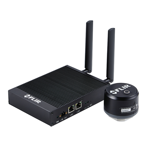
Introduction The FLIR Vibration Monitoring Solution consists of the GW66 Remote Moni- toring Gateway and SV88 (three axis) / SV89 (single axis) Vibration Sensors. This system allows you to monitor vibration and temperature on a variety of machinery and appliances over a local network. The GW66 has a built-in user interface that allows you to configure and control the entire system directly from your Windows®... - Page 9 Introduction Figure 2.4 Monitoring vibration and temperature in chillers. Vibration measurements encompass the frequency (velocity), amplitude (strength), and acceleration (intensity) of the vibration. Figure 2.5 Vibration frequency (left), amplitude (centre), and acceleration (right) Vibration measurements provide insight into potential mechanical issues. This device is well suited for identifying imbalances, eccentricity, loose parts, and misalignment.
-
Page 10: Safety
• Please read all safety information and user manual instructions before us- ing these devices. • No user serviceable equipment. Please contact FLIR for all service and re- pair inquiries. • Use these devices only as described in the provided documentation. Fail- ure to do so can impair the devices’... -
Page 11: Fcc Class A Caution
Safety 3.1 FCC Class A Caution FCC Warnings. Applicability: Class A digital devices. This equipment has been tested and found to comply with the limits for a Class A digital device, pursuant to part 15 of the FCC Rules. These limits are designed to provide reasonable protection against harmful interference when the equipment is operated in a commercial environment. -
Page 12: Product Descriptions
Product Descriptions 4.1 GW66 Gateway Description The GW66 gateway is first used as a local stand-alone 2.4 GHz network for configuring your monitoring system (adding and connecting sensors, custom- izing sensor names, etc.). Once the system is configured, you then connect the GW66 to the local net- work. -
Page 13: Sensor Description
Product Descriptions 4. Mounting holes (ground lug also located on this side on some versions). Figure 4.2 GW66 side access panel. 1. Earth ground connection. On some versions the connection is on the op- posite side. 2. Power status LED lamp. Blinks green while powering. Solid green when fully powered. - Page 14 Product Descriptions Sensors can be bolted onto machinery or the optional mounting base (FLIR TA88) can be used. Sensors measure Acceleration in gravitational units (g) and surface tempera- ture in ℃ or ℉ units. Velocity data are derived from internal calculations and displayed in mm/s or in/s units (millimetres or inches per second).
-
Page 15: Sensor Battery Installation And Replacement
Product Descriptions Figure 4.4 Inside view of sensor 1. Battery compartment. 2. Reset button. 3. Battery SAFT LS17500 (supplied) 4. LED status lamps (see Table 4.1, below). 5. Battery connecting cable. Remove and reattached to cycle power to the sensor. 4.3 Sensor Battery Installation and Replacement Sensors are battery powered using a SAFT LS17500 battery type (supplied), the battery holder is located inside the sensor housing, as shown in Fig. - Page 16 Product Descriptions Figure 4.5 To remove the battery, push it out of its holder through the access hole, indicated by the arrow, using a nonconducting tool (plastic or wood). Table 4.1 Color-coded sensor LED lamp activity when powering the sensor. Blue The two LED lamps blink twice in blue if the sensor is new and has never been connected to a GW66.
-
Page 17: Sensor Battery Life
Product Descriptions 4.4 Sensor Battery Life Sensors are powered when a SAFT LS17500 battery (supplied) is installed in the sensor. To install or replace the battery, refer to Section 4.3. Refer to the graphs, below, for battery life estimation. Figure 4.6 SV88 battery life estimation. The shorter the measurement sampling rate, the more the drain on the battery. -
Page 18: Web-Server User Interface Overview
Product Descriptions 4.5 Web-Server User Interface Overview The vibration monitoring system is controlled from your PC and mobile devi- ces using the web-server application built-in to the GW66, accessible via the Microsoft® Edge® browser (using New InPrivate Window mode), Google® Chrome®... -
Page 19: System Architecture
System Architecture Figure 5.1 System Architecture. Figure 5.1, above, is divided by the vertical dashed line to illustrate the differ- ence between the configuration stage (left) and the in-practice stage (right). • The left side of Figure 5.1, above, shows the local GW66 2.4 GHz network, which your PC and mobile devices initially connect with while configuring the system. - Page 20 System Architecture • On the bottom, right, of Figure 5.1, the PC and mobile devices are shown communicating over your network. It’s important to understand that, first, the PC and mobile devices connect to the GW66’s local network for config- uring and adding sensors, etc.
-
Page 21: Conventional And Advanced Applications
Modbus, MQTT, or OPC UA. These systems offer advanced vibration data analysis and database management. Sections 11.12, 11.13, and 11.14 provide basic information on these hosts, but separate application notes should be obtained from the FLIR support site for complete information. Figure 6.1 Conventional and advanced use. -
Page 22: Setting Up The Gw66 Gateway
Setting up the GW66 Gateway CAUTION The GW66 should not be mounted at a height exceeding 6.6 ft. (2 m). Refer to the Product Descriptions, in Section 4, when following the steps below. For the initial setup you do not need to be in the area where the system will ul- timately be used. -
Page 23: Configuring The Vibration Monitoring System
Configuring the Vibration Monitoring System 8.1 Connecting to the GW66 2.4 GHz Network As mentioned, the GW66 has its own 2.4 GHz network that you use to config- ure the system by adding/naming sensors, and other tasks. Note that the sen- sors always communicate over this network, and communicate only through the GW66, even when the GW66 is later connected to your network. -
Page 24: Preparing Sensors
Configuring the Vibration Monitoring System 8. Type the default password (admin) when prompted. Change the pass- word per Section 11.11. 9. When you successfully connect with the GW66 network the Configuration window will appear in the browser. Customize the system using this win- dow, refer to Section 11 for detailed information on the Configuration window. -
Page 25: The Sensor List Field In The Web-Server Interface
Configuring the Vibration Monitoring System 4. The GW66 will recognize the sensor and the web-server interface will show the detected sensor in the ID field. If you do not see the sensor listed, press F5 on the PC to refresh the web-server page (or click Re- fresh in the ID field). -
Page 26: Sensor Reset Button
LED lamps turn from white to green. After several seconds, the lamps should blink twice (green), indicating that the sensor has started sending its data to the gateway. If the lamps blink yellow twice, the operation has failed. Contact FLIR support if problems persist. #NAS100162; r. AG/98094/98104; en-US... -
Page 27: Restart The Sensor And Set The Measurement Rate
Configuring the Vibration Monitoring System 8.6.4 Restart the Sensor and Set the Measurement Rate Press and hold the reset button for 5 seconds, release the button when the LED lamps turn from white to green to blue. Wait several seconds and if the LED lamps blink green twice, the sensor has been successfully reset. -
Page 28: Connect Gw66 To The Local Network
Connect GW66 to the Local Network Once the system has been configured, as covered in previous sections, it’s time to move the components of the system to its permanent location. In this section we’ll connect to the local 5 GHz network, place sensors, and more. You can connect over the 5 GHz network using Wi-Fi, or directly to the router or modem using the GW66 LAN1 or LAN2 Ethernet port. - Page 29 Connect GW66 to the Local Network 4. Type your local Wi-Fi router’s ESSID (network) username and password and then click SAVE & APPLY. Figure 9.1 Connecting to the 5 GHz Wi-Fi Network. 5. If connection is successful, the 5 GHz LED lamp on the GW66 will blink, indicating data transfer.
- Page 30 Connect GW66 to the Local Network 7. Reconnect Wi-Fi to the assigned SSID (in the example, below: TDYFLIR- TPB), right-click the Microsoft Edge browser icon, and select NEW InPri- vate window. 8. Enter the assigned floating IP address noted earlier, in the browser’s ad- dress bar, and type the password (admin) in the password field.
-
Page 31: Connect The Gw66 Using Ethernet
Connect GW66 to the Local Network 9.2 Connect the GW66 using Ethernet Connect an Ethernet cable (not supplied) from the GW66 LAN1 or LAN2 port to your internet modem or router. The LAN2 port can not accept power, while the LAN1 port can (Power Over Ethernet, or PoE). Figure 9.2 Connecting an Ethernet cable to the GW66. - Page 32 Connect GW66 to the Local Network 5. Enter the assigned floating IP address (minus the digits to the right of the forward slash), noted earlier, in the browser’s address bar and type the password (admin) in the password field. Change the password per Sec- tion 11.11.
-
Page 33: Sensor Installation
10.2 Mounting the Sensors Sensors have a mounting socket on their base. You can bolt the sensor to the equipment or purchase an optional magnetic mounting base (FLIR TA88) that mates to the threaded hole on the base (bottom) of the sensor. Sensors... - Page 34 Sensor Installation Figure 10.1 Examples of areas to place sensors. Figure 10.2 Sensors shown mounted on machinery. #NAS100162; r. AG/98094/98104; en-US...
-
Page 35: Where Sensors Should Not Be Placed
Sensor Installation 10.3 Where sensors should not be placed CAUTION Do not mount sensors on the following locations: • Motor winding areas • Middle of motor • Pump casing • Cooling fan fins/covers • Coupling belt guards, gearboxes • Seal locations Figure 10.3 Examples of places you should not mount sensors. -
Page 36: Documenting Sensor Locations
Sensor Installation 10.5 Documenting Sensor Locations It is important to document the sensor information and test point locations for all equipment in a test system, as discussed in Section 12. Having accurate documentation helps locate, track, and assess equipment easily for preventive maintenance programs and servicing. #NAS100162;... -
Page 37: Web-Server User Interface
Web-Server User Interface The user interface has been discussed briefly in previous sections. In this sec- tion each page of the interface is explained in detail. The user interface is built into the GW66 and is accessed by right-clicking the Microsoft Edge browser icon and selecting New InPrivate Window (you can also use Google Chrome’s New Incognito Window or Firefox’s New Private Window). - Page 38 Web-Server User Interface 6. Right click on the Microsoft Edge browser (or other browser) to open a New InPrivate window, as shown here. 7. Type 192.168.2.1 in the address bar, as shown here. 8. Type the default password (admin) when prompted. Change the pass- word per Section 11.11.
-
Page 39: Dashboard Page
Web-Server User Interface 11.2 Dashboard Page The Dashboard is the first page that appears in the interface. Here you can select other pages and view connected sensor data. Refer to Figure 11.1, be- low for details. Figure 11.1 The main Dashboard for the web-based user interface, built-in to the GW66. 1. -
Page 40: Sensor List Page
Web-Server User Interface 11.3 Sensor LIST Page Figure 11.2 Sensor LIST page. 1. Select Sensor > Sensor List to open this page. 2. Sensors currently connected. 3. Sensor names. 4. Most recent measurement date and time. 5. Sensor alarm status. Green is normal, Red is a high (danger) alarm, Yel- low is a moderate alarm. -
Page 41: Sensor Data Page
Web-Server User Interface 11.4 Sensor DATA Page Figure 11.3 Sensor DATA page. #NAS100162; r. AG/98094/98104; en-US... -
Page 42: Sensor Add Page
Web-Server User Interface 1. Click Sensor > Sensor Data to open this page. 2. View sensor readings. Each column represents one sensor’s reading and alarm status. 3. The FFT graph (see Section 13 for details). 4. Graphical representation of readings separated by axis (x,y,z). 5. -
Page 43: Sensor Edit Page
Web-Server User Interface 11.6 Sensor EDIT Page Figure 11.5 Sensor EDIT page. 1. Click Sensor > Edit Sensor to open this page. 2. Select the sensor to edit from the drop-down menu. 3. Rename the sensor, if desired. 4. Change the sensor’s measurement rate. 5. -
Page 44: Configuration Overview Page
Web-Server User Interface 11.7 Configuration OVERVIEW Page Figure 11.6 Configuration Overview page. 1. Click Configuration > Overview to open this page. 2. View system settings. 3. View Network settings. 4. View Wi-Fi data, signal-to-noise ratio, and transmit/receive rates. 5. Click to refresh the page. 6. -
Page 45: Configuration Setup (General) Page
Web-Server User Interface 11.8 Configuration Setup (General) Page Figure 11.7 Configuration Setup — GENERAL page. 1. Click Configuration > Setup to open this page. 2. Click the General tab. 3. View the device date/time. 4. Click to sync the clock with the browser or the server. 5. -
Page 46: Configuration Setup (Tcp/Ip) Page
Web-Server User Interface 11.9 Configuration Setup (TCP/IP) Page Figure 11.8 Configuration Setup (TCP/IP) page. 1. Click Configuration > Setup to open this page. 2. Click TCP/IP. 3. Select DHCP (dynamic host configuration protocol). 4. Click Save & Apply to save your changes or click Reset to abort. 11.10 Configuration Setup (Wi-Fi) Page Figure 11.9 Configuration Setup (Wi-Fi) page. -
Page 47: Configuration Setup (Admin) Page
Web-Server User Interface 11.11 Configuration Setup (ADMIN) Page Figure 11.10 Configuration Setup (Administration) page. 1. Click Configuration > Setup to open this page. 2. Click the Administrator tab. 3. Upload a firmware update file to upgrade the GW66. 4. Download a data backup file or upload a previously saved data backup file. 5. -
Page 48: Modbus Tcp Host Utility
Basic setting information is supplied below, but complete instructions for using this host are available as a separate application note. Download a copy of the application note from the FLIR support site. Figure 11.11 Modbus TCP Host Settings. 1. Click Protocol > Modbus TCP to open this page. -
Page 49: Opc Ua Host Utility
Basic setting information is supplied below, but complete instructions for using this host are available as a separate application note. Download a copy of the application note from the FLIR support site Figure 11.13 OPC UA Host Settings. 1. Click Protocol > OPC UA to open this page. -
Page 50: Mapping A Test Site
Mapping a Test Site To best maintain a test site, it is important to keep a list of machinery under test, including their types, classifications, and locations. Depending on the size of the operation, a site map may also be needed to show machine loca- tions and the test points where sensors are attached. -
Page 51: Fast Fourier Transform (Fft)
Fast Fourier Transform (FFT) 13.1 Background In simple terms, FFT is a mathematical algorithm that converts a data presen- tation (graph, for example), shown as a function of time, into a data presenta- tion shown as a function of frequency and vice versa. This is useful in the representation of vibration measurements. - Page 52 Fast Fourier Transform (FFT) • Shaft balance issues cause large radial variations and marked increase in amplitude of the fundamental frequency. • Misalignments are shown as an increase in frequency amplitude at the 2nd harmonic. • Looseness is evidenced by a marked increase in the number of harmonics. If there is looseness in the main support of the asset, an increase in the fundamental frequency amplitude will also be noticed.
-
Page 53: Specifications
Specifications 14.1 GW66 Specifications System Memory DDR 512 MB Storage 32 MB NOR Flash Clock On chip RTC with super capacitor backup, with RTC/WDT LED Indicators WAN, LAN, 2.4GHz, 5GHz, Power/Status Wi-Fi 2.4GHz and 5GHz dual band Software Operating System Built-in web-server (Linux) Communication Protocol MQTT, Modbus TCP, and OPC UA... -
Page 54: Sensor Specifications
IP rating IP66 Mounting Bolt/screw (1/4” x 28 UNF) or optional magnetic base mount (FLIR TA88) Sensors should not be mounted at a height > 6.6 ft. (2 m) Operating temperature -4 to 176℉ (-20 to 80℃) #NAS100162; r. AG/98094/98104; en-US... - Page 55 Specifications Storage temperature -4 to 176℉ (-20 to 80℃) Operating humidity 10% to 95% relative humidity, non-condensing Certifications EU (CE & UKCA) FCC (US), IC (Canada) RCM (AUS & NZ) Warranty Three-Year Limited Warranty #NAS100162; r. AG/98094/98104; en-US...
-
Page 56: Firmware Upgrades
The system firmware can be updated in the field by the user. The firmware up- date files are available on the FLIR support website. Follow the steps in the procedure below to perform the update, contact FLIR support if you need assistance. - Page 57 Firmware Upgrades 6. Reconnect the GW66 through Wi-Fi (2.4 GHz) to complete the process. #NAS100162; r. AG/98094/98104; en-US...
-
Page 58: Customer Support
Customer Support Customer Support Telephone List https://support.flir.com/contact Repair, Calibration, and Technical Support https://support.flir.com #NAS100162; r. AG/98094/98104; en-US... -
Page 59: Limited 3-Year Warranty
Limited 3–Year Warranty This product is protected by FLIR’s Limited 3-Year Warranty. Visit www.flir.com/testwarranty to read the warranty document. #NAS100162; r. AG/98094/98104; en-US... - Page 60 #NAS100162; r. AG/98094/98104; en-US...
- Page 62 Customer support http://support.flir.com Copyright © 2024, FLIR Systems, Inc. All rights reserved worldwide. Disclaimer Specifications subject to change without further notice. Models and accessories subject to regional market considerations. License procedures may apply. Products described herein may be subject to US Export Regulations.
Need help?
Do you have a question about the SV88-KIT and is the answer not in the manual?
Questions and answers