
Related Manuals for FLIR IMAGING MOISTURE METER with IGM MR160


Summary of Contents for FLIR IMAGING MOISTURE METER with IGM MR160
- Page 1 USER MANUAL FLIR MODEL MR160 IMAGING MOISTURE METER with IGM GlobalTestSupply www. .com Find Quality Products Online at: sales@GlobalTestSupply.com...
-
Page 2: Table Of Contents
5.1.1 Auto Power OFF (APO) 5.2 Moisture Measurements 5.2.1 Moisture Measurement Overview 5.2.2 Moisture Displays Overview 5.2.3 IMAGE Modes 5.2.4 MOISTURE Modes 5.2.5 Internal Moisture Sensor Measurements (Pinless) 5.2.6 External Pin Probe Moisture Measurements 5.2.7 Reference Mode Moisture Measurements 5.3 Thermal Imager (IR) 5.4 Lock/Unlock Palette Auto‐Scale Mode 5.5 Screen Capture and Hold 5.6 ‘Combination’ Feature 5.7 High Moisture Alarm 5.8 SETTINGS Menu FLIR MR160 USER MANUAL Document Identifier: MR160‐en‐US_AD GlobalTestSupply www. .com Find Quality Products Online at: sales@GlobalTestSupply.com... - Page 3 21 6.1 Cleaning 6.2 Battery Charging 6.2.1 Disposal of Electronic Waste 6.3 Updating the MR160 firmware 7. SPECIFICATIONS 23 8. TECHNICAL SUPPORT 25 9. MATERIAL GROUPS 26 9.1 Common Names of Timbers (BS888/589:1973) with MR160 Group Nos. 9.2 Botanical names of timbers with MR160 program group numbers 9.3 %WME Table (% Wood Moisture Equivalent) 10. WARRANTY 31 10.1 FLIR Test & Measurement 2 year/10 year Limited Warranty FLIR MR160 USER MANUAL Document Identifier: MR160‐en‐US_AD GlobalTestSupply www. .com Find Quality Products Online at: sales@GlobalTestSupply.com...
-
Page 4: Disclaimers
1. Disclaimers 1.1 Copyright © 2014‐2016 FLIR Systems, Inc. All rights reserved worldwide. No parts of the software including source code may be reproduced, transmitted, transcribed or translated into any language or computer language in any form or by any means, electronic, magnetic, optical, manual or otherwise, without the prior written permission of FLIR Systems. The documentation must not, in whole or part, be copied, photocopied, reproduced, translated or transmitted to any electronic medium or machine readable form without prior consent, in writing, from FLIR Systems. Names and marks appearing on the products herein are either registered trademarks or trademarks of FLIR Systems and/or its subsidiaries. All other trademarks, trade names or company names referenced herein are used for identification only and are the property of their respective owners. 1.2 Quality Assurance The Quality Management System under which these products are developed and manufactured has been certified in accordance with the ISO 9001 standard. FLIR Systems is committed to a policy of continuous development; therefore we reserve the right to make changes and improvements on any of the products without prior notice. 1.3 Documentation To access the user manuals, extended warranty registration, firmware updates, and notifications go to the Download tab at: In the download area you will also find the latest releases of manuals for our other products, as well as manuals for our historical and obsolete products. The extended warranty page can also be found at 1.4 Disposal of Electronic Waste As with most electronic products, this equipment must be disposed of in an environmentally friendly way, and in accordance with existing regulations for electronic waste. Please contact your FLIR Systems representative for more details. FLIR MR160 USER MANUAL Document Identifier: MR160‐en‐US_AD GlobalTestSupply www. .com Find Quality Products Online at:... -
Page 5: Safety
2. Safety 2.1 Safety Notes Before operating the device, you must read, understand, and follow all instructions, dangers, warnings, cautions, and notes. FLIR Systems reserves the right to discontinue models, parts or accessories, and other items, or to change specifications at any time without prior notice. 2.2 Laser Safety Warning Statement Do not look directly into the laser beam. The laser beam can cause eye irritation. FLIR MR160 USER MANUAL Document Identifier: MR160‐en‐US_AD GlobalTestSupply www. .com Find Quality Products Online at: sales@GlobalTestSupply.com... -
Page 6: Introduction
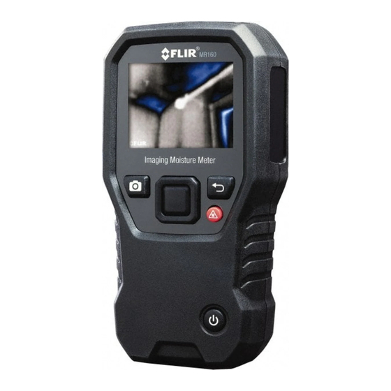
Featuring Infrared Guided Measurement (IGM ) technology, the MR160 helps to quickly scan and target moisture issues; visually guiding the user to the spot where measurements can be confidently made and where readings can be easily analyzed. The MR160 can save measurements and images for later transfer to a PC; reports can be generated with FLIR Tools PC software. Please see for additional accessories available for this device. This device is shipped fully tested and calibrated and, with proper use, will provide years of reliable service. Please register the FLIR MR160 within 60 days of purchase for extended warranty at the following location: 3.1 Key Features FLIR Lepton® microbolometer Focal Plane Array (FPA) with integrated shutter delivers best in class thermal imaging Quickly scan for moisture using the integrated non‐invasive pinless moisture sensor External pin probe (included) for resistive moisture content measurements IGM Moisture mode displays both the thermal image and moisture readings on one screen Moisture mode shows Pin or Pinless moisture readings with large digits and color bargraph Scale Lock adds precision to thermal image scanning Capture, view, & delete thermal images and measurements Nine (9) material group selections for pin‐based readings Programmable high moisture alarm with audible and color visual alerts Laser pointer and display crosshairs for targeting of anomalies found on thermal image Easy to read, color display with intuitive graphical interface and tool tips in local languages File management, image review, & report generation with free FLIR Tools PC software via USB Internal rechargeable battery with USB based international charger ... -
Page 7: Meter And Menu Icon Descriptions
5. Back button 6. Laser Pointer / Crosshairs button 7. Power button 8. USB, External Probe jack, and charge LED 9. Laser pointer lens (back) 10. Thermal imaging lens (back) 11. Internal Pinless Moisture sensor (back) 12. Micro USB Port (bottom) 13. External Probe Jack (bottom) 14. Battery Charging LED status lamp (bottom) Fig. 4‐1 Meter Description FLIR MR160 USER MANUAL Document Identifier: MR160‐en‐US_AD GlobalTestSupply www. .com Find Quality Products Online at: sales@GlobalTestSupply.com... -
Page 8: Control Buttons
4.2 Control Buttons Image Capture button: Press to save a ‘screen‐shot’. Refer to section 5.5 Screen Capture and Hold for full details. Back button. Press to back up or return from a menu screen. Press to activate laser pointer/crosshairs in thermal imaging modes. Press to power the meter ON. Press and hold to power the meter OFF. Press the Select button (center) to access the Main Menu. Use this button to select items from within the menu structure. Use the four outer navigation (rim) buttons to move up‐down‐left‐ right. FLIR MR160 USER MANUAL Document Identifier: MR160‐en‐US_AD GlobalTestSupply www. .com Find Quality Products Online at: sales@GlobalTestSupply.com... -
Page 9: Menu Map And Overview
Lock/Unlock Palette Auto‐Scale: Select Lock to adjust the color palette range to suit a given application (see Section 5.4 Lock/Unlock Palette Auto‐Scale Mode for more detail). Unlock for normal auto‐scaling operation. Settings utility: Language, Palette, High Alarm, Auto Power OFF, Date & Time, Help contact screen, and Meter Information screen. Icons 6 through 9 in Fig. 4‐2 are available in the Moisture Mode Menu. Press icon 3 to view these Moisture modes. A blue dot is shown to the left of the pin icon (7) or the pinless icon (8), depending on which is selected. Material Group: Select the material under test (Groups 1~9); For Pin Mode only. See Section 9 for Wood and Material Group listings. Pin mode: Select this mode when using external pin moisture probe. Pinless mode: Select this mode when using the internal (rear) moisture sensor. Set Reference: Select this mode to store the current reading as a reference value. For pinless mode only. Icons 10 through 12 in Fig. 4‐2 are available in the Image Mode Menu. Press icon 2 to view the Image Mode menu. 10. IR (View Thermal Image only) 10 11 12 11. IR + IGM Moisture (View Thermal Image + Moisture readings) 12. Moisture only 3 4 5 Fig. 4‐2 Menu Icons FLIR MR160 USER MANUAL Document Identifier: MR160‐en‐US_AD GlobalTestSupply www. .com Find Quality Products Online at: sales@GlobalTestSupply.com... -
Page 10: Operation
Please fully charge the battery before use. 5.1.1 Auto Power OFF (APO) The meter switches OFF automatically after a programmed period of inactivity. Press any button to reset the APO timer. To disable APO, or to change the APO time‐out value, use the Settings mode, accessible from the Main Menu. The default time‐out is 20 minutes. 5.2 Moisture Measurements 5.2.1 Moisture Measurement Overview Moisture measurements can be performed using either the internal pinless moisture sensor (rear) or by connecting an external probe. A standard external pin probe is included which connects to the MR160 via the jack at the bottom of the meter. Other external probes are available; please visit for details. NOTE: Objects in close proximity to the internal pinless moisture sensor (located on the rear of the unit) will affect the reading on the display; Keep hands and fingers clear of the sensor when taking measurements. The internal moisture sensor detects moisture to a depth of approximately 19mm (0.75”). The actual depth will vary depending upon the amount of moisture, the material under test, surface roughness, and other factors. Moisture readings are shown on the display (digitally and with bar graph) in the Moisture‐only mode or in small digits (upper left hand corner) in the IR + IGM Moisture mode. See Fig. 5‐1. Pinless measurement readings are ‘relative’ scaled (0~100). Pin‐based readings are represented in terms of %MC (moisture content) for wood and %WME (wood moisture equivalent) for non‐ wood materials; additional information is provided in Section 5.2.6 External Pin Probe Moisture Measurements and in the specifications. Moisture measurements are covered in detail in the following sections. Be sure to select Pin Mode or Pinless Mode in the Moisture Menu to match the measurement type. FLIR MR160 USER MANUAL Document Identifier: MR160‐en‐US_AD GlobalTestSupply www. .com Find Quality Products Online at: sales@GlobalTestSupply.com... -
Page 11: Moisture Displays Overview
6. Cross‐hairs 7. Thermal image Fig. 5‐1(a) IR + IGM Image Mode Fig. 5‐1 (b) Moisture‐only Mode 1. Moisture reading (digital) 2. Moisture reading (bargraph); Bars are blue when in non‐alarm state and red when in an alarm state. 3. Selected Mode 4. High Moisture Alarm threshold (see Section 5.7) Fig. 5‐1(b) Moisture‐only Mode 5. Set Reference value (see Set Reference mode in Sections 5.2.3 and 5.2.6); pinless mode only. Note that in Pin mode this display area will show the selected Material/Wood Group. Access the Moisture Mode to select the Material/Wood Group. FLIR MR160 USER MANUAL Document Identifier: MR160‐en‐US_AD GlobalTestSupply www. .com Find Quality Products Online at: sales@GlobalTestSupply.com... -
Page 12: Image Modes
5.2.3 IMAGE Modes Press the Select button to access the Main Menu and then select the IMAGE mode icon (1). Refer to Fig. 5‐2. Choose Thermal IR Image‐only mode (2), IR + IGM Moisture mode (3), or Moisture‐only mode (4). Each mode is described below. Image mode icon in the Main Menu IR Thermal Image mode only Fig. 5‐2 Image mode In the IR mode the meter displays only the IR Thermal Camera image. See Fig. 5‐6 IR + IGM Moisture mode In the IR + IGM Moisture mode the meter displays the IR Thermal Camera Image and the moisture reading text (upper left hand corner) and the pin or pinless mode icon (depending on which is currently selected). See Fig. 5‐1(a). Moisture reading only In the Moisture only mode the IR Thermal Camera Image is off and the meter shows only the moisture reading in digits and in bargraph formats, see Fig. 5‐1(b). FLIR MR160 USER MANUAL Document Identifier: MR160‐en‐US_AD GlobalTestSupply www. .com Find Quality Products Online at: sales@GlobalTestSupply.com... -
Page 13: Moisture Modes
(3) on the upper left of the main display when selected. 4. PINLESS MODE PINLESS mode must be selected when using the internal sensor. Note the pinless icon (4) on the upper left of the main display when selected. 5. SET REFERENCE MODE SET REFERENCE is used to compare the displayed readings against a stored reference measurement (see Section 5.2.7 Reference Mode). This mode applies only to readings taken with the pinless internal sensor. 5.2.5 Internal Moisture Sensor Measurements (Pinless) 1. Follow the steps in Section 5.2.1 through 5.2.4 and select the Pinless mode. 2. Place the internal moisture sensor (back) on the surface of the material to be tested. Apply light pressure to ensure that the internal sensor is completely flat against the surface of the material under test. 3. The relative moisture reading is displayed on the main display in the upper left hand corner (IR + IGM Moisture mode) or as bargraph with accompanying digits (Moisture‐ only mode). Refer to example screens shown in Fig. 5‐1. 4. Keep hands, surfaces, and objects away from the rear internal moisture sensor area when taking measurements. 5. For best results, lift the meter off of the surface under test between measurement points; do not drag the meter over surfaces. FLIR MR160 USER MANUAL Document Identifier: MR160‐en‐US_AD GlobalTestSupply www. .com Find Quality Products Online at: sales@GlobalTestSupply.com... -
Page 14: External Pin Probe Moisture Measurements
5.2.6 External Pin Probe Moisture Measurements 1. Follow the steps in Section 5.2.1 through 5.2.4 and select Pin mode from the MOISTURE mode options. 2. Connect the external pin probe to the meter’s EXT jack on the bottom of the meter (under the protective flap). Refer to the FLIR website for information on available external pin moisture probe types. 3. Select the appropriate Material Group as described in Section 5.2.4 (see Section 9 for the Material Group Appendices). Note: Use Group 9 for building materials. 4. Press the pins into the material under test. 5. The moisture reading is displayed on the main display (%) in the upper left hand corner (IR + IGM Moisture mode) or as a bargraph with accompanying digits (Moisture‐only mode). Refer to example screens shown in Fig. 5‐1. Notes on External Pin Probe Moisture measurements The MR160 will display accurate external pin probe readings in the 7% to 30% range, depending on the tested material. Moisture Content readings below 6% will display as 0% for all materials and the maximum specified range is dependent on the fiber saturation point for specific species. Above the fiber saturation point, the reading can only be used as a relative reference value. For more information on fiber saturation please refer to ASTM D7438. For additional information on Pin moisture measurement accuracy please see ASTM D4444, section 6. FLIR MR160 USER MANUAL Document Identifier: MR160‐en‐US_AD GlobalTestSupply www. .com Find Quality Products Online at: sales@GlobalTestSupply.com... -
Page 15: Reference Mode Moisture Measurements
4. To remove the reference value and exit the mode: Remove the meter sensor from the area under test, so that the sensor is no longer touching a surface and is clear of any objects (keep hands away from the sensor also), and then press the Set Reference icon again. The reference value will no longer be visible on the meter display. 5.3 Thermal Imager (IR) The full screen IR Thermal Imager is active in the IR ‐only mode and the IR + IGM Moisture mode (selectable from the IMAGE mode icon in the Main Menu). The Thermal Imager lens is located on the back of the meter. Face the lens toward the area of interest and view the image on the meter display. Select the IR thermal image display color palette from the Settings menu. Select IRON, RAINBOW, ICE, or GREYSCALE; see examples in Fig. 5‐4. For example: the ICE palette hot to cold temperatures, for images, are represented by this color palette progression: white>grey>black>blue>white. See the color palette example below in figure 5‐5(c). For the ICE palette, the right side of the scale shows the hotter pixels in the frame, and the left side of the scale shows the coldest pixels. FLIR MR160 USER MANUAL Document Identifier: MR160‐en‐US_AD GlobalTestSupply www. .com Find Quality Products Online at: sales@GlobalTestSupply.com... - Page 16 Fig. 5‐4 Thermal IR Image Color Palettes Fig. 5‐4(a) ‐ IRON PALETTE Fig. 5‐4(b) ‐ RAINBOW PALETTE Fig. 5‐4(c) ‐ ICE PALETTE Fig. 5‐4(d) ‐ GREY PALETTE When the Laser Pointer button is pressed, and held to activate the laser pointer, the display crosshairs also switch on, for additional targeting flexibility. Refer to Fig. 5‐5. Note that the laser is carefully aimed to align with the crosshairs for easier identifying and targeting of objects and surfaces. 1. Laser icon (Press and hold Laser button to activate) 2. Crosshairs (Press and hold Laser button to activate) 3. IR Thermal Image Fig. 5‐5 Thermal IR Image FLIR MR160 USER MANUAL Document Identifier: MR160‐en‐US_AD GlobalTestSupply www. .com Find Quality Products Online at: sales@GlobalTestSupply.com...
-
Page 17: Lock/Unlock Palette Auto-Scale Mode
Fig. 5‐6(a) Palette auto‐scale unlocked Fig. 5‐6(b) Palette auto‐scale locked away from hot object If the user wishes to narrow the range of color and limit it to colors near the cold temperature image, Lock/Unlock can be set to ‘Lock’ with no hot objects in the frame. To lock the scale, press the Select button to access the Main Menu, scroll to the Lock icon, and press Select again to toggle unlock/lock. Some experimentation and fine‐tuning may be required to get the best possible contrast for the application. 5.5 Screen Capture and Hold Pressing the Image Capture button captures the current MR160 screen. The screen will hold (freeze) for seven (7) seconds, until an image file‐name appears indicating that the image has been saved. During the seven second ‘hold’ period, the user can simply examine the image and press the Back button to discard or press Select/Capture to save the image. Images are saved in bitmap (.bmp) format. Images can be accessed on the MR160 screen using the Image Review icon available in the Main Menu. Then scroll the images using the Left and Right navigation buttons. FLIR MR160 USER MANUAL Document Identifier: MR160‐en‐US_AD GlobalTestSupply www. .com Find Quality Products Online at: sales@GlobalTestSupply.com... -
Page 18: Combination' Feature
Images can also be transferred to computer or other compatible device using the MR160 USB port (bottom of meter, under flap) and supplied USB cable. 5.6 ‘Combination’ Feature: Save Thermal Image with Pinless Moisture Reading The Combination feature allows the user to ‘freeze’ a thermal image and take a pinless moisture reading, saving both the thermal image and the moisture reading on a single image. The ‘held’ thermal image, with continuous moisture reading shown on the same screen, can then be captured as explained in Section 5.5 above. Enter the IR + Moisture Image mode (refer to Section 5.2.3 Image Mode). Hold the Image Capture button until crosshairs appear and the laser is visible (Fig. 5‐7(a)). While continuing to hold the Capture button, aim the laser at the measurement spot. Release the Capture button. The image will freeze but the moisture reading will flash and continue to update as it waits for a measurement. Place the pinless measurement sensor pad of the MR160 against the item targeted by the laser pointer to make the moisture measurement. Press the Select button to capture (save) the image; note that the image will include the moisture reading; see Fig. 5‐7(b). After a seven second hold period, an image file‐name will appear on the screen (FLIRxxxx.bmp), indicating that the image has been saved. During this time‐out period, the user can press Back to cancel the image capture, or Select/Capture to save the image. Fig. 5‐7(a) Laser and Crosshairs visible; Aim the Laser at the test surface Fig. 5‐7(b) Saved image with Target area and Moisture reading FLIR MR160 USER MANUAL Document Identifier: MR160‐en‐US_AD GlobalTestSupply www. .com Find Quality Products Online at: sales@GlobalTestSupply.com... -
Page 19: High Moisture Alarm
5.7 High Moisture Alarm The MR160 offers a High Moisture Alarm where an audible and visual alert activates when the moisture reading exceeds the programmed high limit. Press the Select button to access the Main Menu Select the SETTINGS mode from the Main Menu Scroll to ALARM and press the Select button to open the Alarm programmer Use the Navigation and Select buttons to switch the alarm ON or OFF and to set the threshold from 0% to 100% Press the Select button to return to the SETTINGS mode and save the value or press the back button to cancel and to return to the normal operating mode When the High Alarm is set ON, the main display will show the alarm bell icon (shown in header above) and the High Alarm threshold value. Refer to example screens shown in Fig. 5‐1. When the measurement exceeds the threshold, the text for the measurement reading will appear red in color and will flash. Note that in the Moisture‐only mode, the bargraph turns red when the Alarm threshold is exceeded. Refer to the example in Fig. 5‐1(b). To switch the alarm OFF when the meter is alarming, press the Select button and then select SETTINGS from the Main Menu FLIR MR160 USER MANUAL Document Identifier: MR160‐en‐US_AD GlobalTestSupply www. .com Find Quality Products Online at: sales@GlobalTestSupply.com... -
Page 20: Settings Menu
RAINBOW, ICE, and GREY selections. Refer to Fig. 5‐4 for example palette screens. Navigate to another Settings option or press the back button to exit the Settings menu. ALARM. Set a high alarm threshold. From the Settings menu, scroll to Alarm and press the Select button. Use the up/down navigation buttons to arm/disarm the alarm (ON/OFF). Use the left/right navigation buttons to select an alarm threshold digit; use the up/down navigation buttons to set the high alarm threshold. Refer to Section 5.7 for Alarm details. The Alarm can be used in pin or pinless mode of operation. Press the Select button to save the value and return to the SETTINGS menu or press the back button to cancel and return to the Settings menu. AUTO POWER OFF. From the SETTINGS menu, scroll to Auto Power OFF and then use the Select button to step through the available options (1, 5, 20 minutes, or OFF). Navigate to another Settings option or press the back button to exit the Settings menu. DATE & TIME. From the SETTINGS menu, scroll to Date & Time and press the Select button. Use the left/right navigation buttons to select YYYY, MM, DD, HH : MM (from left to right) and use the up/down navigation buttons to change the digits. Press the Select button to save the value and return to Settings menu or press the back button to cancel and return to the normal operating mode. The next items are located on the 2 page of the Settings menu; use the navigation buttons to scroll down: HELP SCREEN. Scroll to HELP and press the Select button to view the company contact information. Press the back button to return to the Settings menu. METER INFORMATION. From the SETTINGS menu, scroll to Meter Information and press the Select button to view the Model, Software Version, and Last Calibration Date information. Press the back button to return to the Settings menu. FLIR MR160 USER MANUAL Document Identifier: MR160‐en‐US_AD GlobalTestSupply www. .com Find Quality Products Online at: sales@GlobalTestSupply.com... -
Page 21: Maintenance
6. Maintenance 6.1 Cleaning Clean the meter with a damp cloth and mild detergent; do not use abrasives or solvents. 6.2 Battery Charging The internal battery is not user serviceable. Please charge the battery before first use. Connect the meter to an AC source or a computer USB port using the supplied USB charger cable. The USB port is located on the bottom of the meter, under the protective flap, next to the EXT Probe jack. While the meter is charging, a blue LED (bottom of meter under protective flap) indicates that charging is successfully taking place. View the battery status icon on the upper left hand corner of the meter’s display when a program menu is active. 6.2.1 Disposal of Electronic Waste As with most electronic products, this equipment must be disposed of in an environmentally friendly way, and in accordance with existing regulations for electronic waste. Please contact your local FLIR Systems representative for more details. FLIR MR160 USER MANUAL Document Identifier: MR160‐en‐US_AD GlobalTestSupply www. .com Find Quality Products Online at: sales@GlobalTestSupply.com... -
Page 22: Updating The Mr160 Firmware
To update the firmware the following is required: Access to the website where the update file(s) are located: The MR160 to be updated The update files Follow the steps below: Visit to check for the latest updates. Select the ‘Downloads’ tab and then select ‘Instrument Firmware’ (Test and Measurement) from the drop down menu. Select MR160 from the second drop down menu. Select and download the updated firmware. Turn the meter on, and connect it to a computer via USB. Copy the update file(s) into the root directory of the MR160 drive (e.g. MR160_v1_962.hex). Disconnect the meter from the USB port. Hold the power button for one second to turn the meter off. Press the power button to turn the meter on again. The screen should remain dark; the unit will beep twice to signal that the update has started. 10. After ~10s it will beep again signaling that the update is complete. 11. Press the power button to turn the meter on; the new version should now be running. 12. If there is an error, repeat the procedure. If a problem persists, contact FLIR technical support. FLIR MR160 USER MANUAL Document Identifier: MR160‐en‐US_AD GlobalTestSupply www. .com Find Quality Products Online at: sales@GlobalTestSupply.com... -
Page 23: Specifications
Product Weight 11.4 oz. (323g) Drop test 3 meter drop test approval pending Certification standards EN61326 (EMC), EN60825‐1 Class 2 (Laser) Agency approvals CE, FCC Class B Included accessories MR01 replaceable Temperature and RH Sensor, MR02 Standard Pin Probe, Quick Start Guide, International USB charger, and USB cable Language options Meter display text can be shown in any of fourteen (14) languages 7.2 Imaging Specifications Thermal imaging camera FLIR Lepton® module, microbolometer FPA (focal plane array) Image calibration Automatic (with manual lock scale option) Thermal image resolution 80(W) x 60(H) pixels (4800 pixels) Spectral response 8~14µm Field of view 51° horizontal x 38° vertical Thermal Sensitivity < 150mK 2 Detection Limit Wet area detection @ 32’ (10m): 19.7in (49cm ) ... - Page 24 External Pin‐based Measurements 7% ‐ 30%* (±1.5% MC*) 30%‐100%* (Reference Only) Measurement Resolution 0.1 Pinless Measurement Depth 0.75” (1.9cm) maximum Pin Moisture Groups Nine (9) material groups Response time Pinless mode: 100ms Pin mode: 750ms Notes: * Maximum specified range is dependent on the fiber saturation point for specific species. Beyond this point, the reading can only be used as a relative reference value. For more information on fiber saturation please refer to ASTM D7438. Accuracy specification is based on the analysis in J. Fernández‐Golfín et al. Actual real‐world accuracy depends on a variety of factors; For more information, refer to ASTM D4444, section 6. **Accuracy spec. applies to pin probe moisture measurements taken on wood whose temperature is 68°F (20°C). Add 0.1% to the accuracy spec. for each °C below 20°C or subtract 0.1% for each °C above 20°C. FLIR MR160 USER MANUAL Document Identifier: MR160‐en‐US_AD GlobalTestSupply www. .com Find Quality Products Online at: sales@GlobalTestSupply.com...
-
Page 25: Technical Support
Cedar, West Indian 8 Maple, Sugar 1 Redwood, Californian 2 Cedar, Western Red 3 Matai 4 Rosewood, Indian 1 Cherry, European 8 Meranti, Red (dark/light) 2 Rubberwood 7 Chestnut 3 Meranti, White 2 Santa Maria 7 Coachwood 6 Merbau 2 Sapele 3 FLIR MR160 USER MANUAL Document Identifier: MR160‐en‐US_AD GlobalTestSupply www. .com Find Quality Products Online at: sales@GlobalTestSupply.com... -
Page 26: Material Groups
3 Gum, American Red 1 Padauk, African 5 Walnut, New Guinea 2 Gum, Saligna 2 Panga Panga 1 Walnut, Queensland 3 Gum, Southern 2 Persimmon 6 Wandoo 8 Gum, Spotted 1 Pillarwood 5 Wawa 6 Whitewood 3 Yew 3 FLIR MR160 USER MANUAL Document Identifier: MR160‐en‐US_AD GlobalTestSupply www. .com Find Quality Products Online at: sales@GlobalTestSupply.com... - Page 27 Canarium schweinfurthii 2 Khaya ivorensis 8 Quercus gigantean 3 Cardwellia sublimes 3 Khaya senegalensis 4 Quercus robur 1 Carya glabra 5 Larix decidua 3 Quercus spp 1 Cassipourea elliotii 5 Larix kaempferi 3 Ricinodendron heudelotti 5 Cassipourea melanosana 5 Larix leptolepis 3 Sarcocephalus diderrichii 7 FLIR MR160 USER MANUAL Document Identifier: MR160‐en‐US_AD GlobalTestSupply www. .com Find Quality Products Online at: sales@GlobalTestSupply.com...
-
Page 28: Botanical Names Of Timbers With Mr160 Program Group Numbers
Entandrophragma angolense 7 Pericopsis elata 6 Ulmus procera 4 Entandrophragma cylindricum 3 Picaenia excelsa 3 Ulmus thomasii 4 Entandrophragma utile 8 Picea abies 3 Xylia dolabriformis 4 Erythrophleum spp 3 Picea jezoensis (18‐28%mc) 3 Zelkova serrata 2 FLIR MR160 USER MANUAL Document Identifier: MR160‐en‐US_AD GlobalTestSupply www. .com Find Quality Products Online at: sales@GlobalTestSupply.com... - Page 29 23.9 27.3 ‐ 27 26.5 ‐ 23.3 23.4 20.8 24.7 28.1 ‐ 28 28 ‐ 24.4 24.8 21.7 25.9 ‐ ‐ 29 29.6 ‐ 25.6 26.3 22.9 27.1 ‐ ‐ FLIR MR160 USER MANUAL Document Identifier: MR160‐en‐US_AD GlobalTestSupply www. .com Find Quality Products Online at: sales@GlobalTestSupply.com...
-
Page 30: Wme Table (% Wood Moisture Equivalent)
10. Warranty 10.1 FLIR Test & Measurement 2 year/10 year Limited Warranty Congratulations! You (the “Purchaser”) are now the owner of a world‐class FLIR Imaging Test and Measurement product. A qualifying FLIR Imaging Test and Measurement product (the “Product”) purchased either directly from FLIR Commercial Systems Inc. and affiliates (FLIR) or from an authorized FLIR distributor that Purchaser registers on‐line with FLIR is eligible for coverage under FLIR’s industry‐leading 2‐10 Limited Warranty, subject to the terms and conditions in this document. This warranty only applies to purchases of Qualifying Products (see below) purchased after July 2014 and only to the original Purchaser of the Product. PLEASE READ THIS DOCUMENT CAREFULLY; IT CONTAINS IMPORTANT INFORMATION ABOUT THE PRODUCTS THAT QUALIFY FOR COVERAGE UNDER THE 2‐10 LIMITED WARRANTY, PURCHASER’S OBLIGATIONS, HOW TO ACTIVATE THE WARRANTY, WARRANTY COVERAGE, AND OTHER IMPORTANT TERMS, CONDITIONS, EXCLUSIONS AND DISCLAIMERS. 1. PRODUCT REGISTRATION. To qualify for FLIR’s 2‐10 Limited Warranty, the Purchaser must fully register the Product directly with FLIR on‐line at WITHIN Sixty (60) DAYS of the date the Product was purchased by the first retail customer (the “Purchase Date”). PRODUCTS THAT ARE NOT REGISTERED ON‐LINE WITHIN Sixty (60) DAYS OF THE PURCHASE DATE OR PRODUCTS WHICH DO NOT QUALIFY FOR THE 2‐10 WARRANTY WILL HAVE A LIMITED ONE YEAR WARRANTY FROM THE DATE OF PURCHASE. 2. QUALIFYING PRODUCTS. Upon registration, a list of thermal Imaging Test and Measurement Products that qualify for coverage under FLIR’s 2‐10 Warranty can be found at 3. WARRANTY PERIODS. The 2‐10 Limited Warranty has two separate periods of warranty coverage (the “Warranty Period”), depending on the Imaging Test and Measurement Product part: Product components (excluding thermal imaging sensor) are warranted for a period of two (2) years from the Purchase Date; Thermal imaging sensor is warranted for a period of ten (10) years from the Purchase Date. Any Product that is repaired or replaced under warranty is covered under this 2‐10 Limited Warranty for one hundred eighty days (180) days from the date of return shipment by FLIR or for the remaining duration of the applicable Warranty Period, whichever is longer. 4. LIMITED WARRANTY. In accordance with the terms and conditions of this 2‐10 Limited Warranty, and except as excluded or disclaimed in this document, FLIR warrants, from the Purchase Date, that all fully registered Products will conform to FLIR’s published Product specifications and be free from defects in materials and workmanship during the applicable Warranty Period. PURCHASER’S SOLE AND EXCLUSIVE REMEDY UNDER THIS WARRANTY, AT FLIR’S SOLE DISCRETION, IS THE REPAIR OR REPLACEMENT OF DEFECTIVE PRODUCTS IN A MANNER, AND BY A SERVICE CENTER, AUTHORIZED BY FLIR. IF THIS REMEDY IS ADJUDICATED TO BE INSUFFICIENT, FLIR SHALL REFUND PURCHASER’S PAID PURCHASE PRICE AND HAVE NO OTHER OBLIGATION OR LIABILITY TO BUYER WHATSOEVER. 5. WARRANTY EXCLUSIONS AND DISCLAIMERS. FLIR MAKES NO OTHER WARRANTY OF ANY KIND WITH ... -
Page 31: Warranty
6. WARRANTY RETURN, REPAIR AND REPLACEMENT. To be eligible for warranty repair or replacement, Purchaser must notify FLIR within thirty (30) days of discovering of any apparent defect in materials or workmanship. Before Purchaser may return a Product for warranty service or repair, Purchaser must first obtain a returned material authorization (RMA) number from FLIR. To obtain the RMA number Owner must provide an original proof of purchase. For additional information, to notify FLIR of an apparent defect in materials or workmanship, or to request an RMA number, visit Purchaser is solely responsible for complying with all RMA instructions provided by FLIR including but not limited to adequately packaging the Product for shipment to FLIR and for all packaging and shipping costs. FLIR will pay for returning to Purchaser any Product that FLIR repairs or replaces under warranty. FLIR reserves the right to determine, in its sole discretion, whether a returned Product is covered under warranty. If FLIR determines that any returned Product is not covered under warranty or is otherwise excluded from warranty coverage, FLIR may charge Purchaser a reasonable handling fee and return the Product to Purchaser, at Purchaser’s expense, or offer Purchaser the option of handling the Product as a non‐warranty return. FLIR shall not be responsible for any data, images or other information that may be stored on the returned Product which was not included in the Product at the time of purchase. It is Purchaser’s responsibility to save any and all data prior to returning the Product for warranty service. 7. NON‐WARRANTY RETURN. Purchase may request that FLIR evaluate and service or repair a Product not covered under warranty, which FLIR may agree to do in its sole discretion. Before Purchaser returns a Product for non‐warranty evaluation and repair, Purchaser must contact FLIR by visiting to request an evaluation and obtain an RMA. Purchaser is solely responsible for complying with all RMA instructions provided by FLIR including but not limited to adequately packaging the Product for shipment to FLIR and for all packaging and shipping costs. Upon receipt of an authorized non‐warranty return, FLIR will evaluate the Product and contact Purchaser regarding the feasibility of and the costs and fees associated with Purchaser’s request. Purchaser shall be responsible for the reasonable cost of FLIR’s evaluation, for the cost of any repairs or services authorized by Purchaser, and for the cost of repackaging and returning the Product to Purchaser. Any non‐warranty repair of a Product is warranted for one hundred eighty days (180) days from the date of return shipment by FLIR to be free from defects in materials and workmanship only, subject to all of the limitations, exclusions and disclaimers in this document. ...
Need help?
Do you have a question about the IMAGING MOISTURE METER with IGM MR160 and is the answer not in the manual?
Questions and answers