
Subscribe to Our Youtube Channel
Related Manuals for FLIR MSX MR277


Summary of Contents for FLIR MSX MR277
- Page 1 USER MANUAL Moisture Meter, MSX® IR Camera, Hygrometer Model MR277 Distributed by: Reduction Revolution Pty Ltd www.reductionrevolution.com.au/FLIR...
- Page 3 USER MANUAL Moisture Meter, MSX® IR Camera, Hygrometer #NAS100005; r. AL/76939/76957; en-US...
-
Page 5: Table Of Contents
Table of contents Advisories ................1 Copyright ..............1 Quality Assurance ............1 Documentation ............1 Disposal of Electronic Waste ......... 1 Introduction................2 Safety ................4 Safety Warnings and Cautions........4 Descriptions ...............5 Product Description............. 5 Control Button Descriptions .......... 6 Display Description ............. 6 Sensor Extension Accessory (MR-EXT) ...... - Page 6 10.3 Deleting images ............47 10.4 Transferring Images via PC Interface......47 10.5 Transmitting Images and Data via Bluetooth®....48 Bluetooth® Communication and FLIR Tools™ Mobile App ................. 49 11.1 FCC Compliance ............49 Field Firmware Updates ............. 51 12.1 System Firmware Update ...........
- Page 7 Table of contents Limited 10–Year Warranty ........... 64 Customer Support............. 65 17.1 Corporate Headquarters ..........65 #NAS100005; r. AL/76939/76957; en-US...
-
Page 9: Advisories
The documentation must not, in whole or part, be copied, photocopied, repro- duced, translated or transmitted to any electronic medium or machine-read- able form without prior consent, in writing, from FLIR Systems. Names and marks appearing on the products herein are either registered trademarks or trademarks of FLIR Systems and/or its subsidiaries. -
Page 10: Introduction
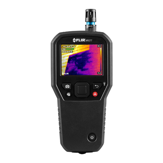
Introduction Thank you for selecting the FLIR MR277. The MR277 integrates high quality thermal imaging and digital camera technology with best-in-class moisture detection and measurement. The MR277 includes an integrated noninvasive pinless moisture sensor, an external pin moisture probe (MR02), a replace- able temperature and relative humidity ambient sensor (MR13), and a sensor extender (MR-EXT). - Page 11 Introduction • Moisture-only mode shows Pin or Pinless moisture readings in large-digit format • Temperature Scale Lock adds precision to thermal image scanning • Easily capture, view, download (to PC), send to mobile devices, and delete camera images • Selectable material groups allow you to fine tune pin-based measurements •...
-
Page 12: Safety
Safety 3.1 Safety Warnings and Cautions WARNING Before operating this device, please read, understand, and follow all operational instruc- tions and safety warnings. CAUTION Use of controls or adjustments or performance of procedures other than those specified herein may result in hazardous radiation exposure. CAUTION Use extreme caution when the Laser pointer is on. -
Page 13: Descriptions
Descriptions 4.1 Product Description Figure 4.1 Front, Back, and Bottom Product Description 1. Temperature and Relative Humidity Sensor (MR13) 2. Color Graphical Display 3. Image Capture button 4. Image Gallery button 5. Select button (center). Press to open Menu 6. Power button 7. -
Page 14: Control Button Descriptions
Descriptions 4.2 Control Button Descriptions Long press to power ON or OFF. Return button. Short press to back out to previous screen in Menu system. Long press to switch Worklight ON or OFF. Press the Select button (center) to access the Main Menu and to select items in the menu system. -
Page 15: Sensor Extension Accessory (Mr-Ext)
Descriptions 7. Mixing ratio calculation in grains per pound (GPP) 8. IR Thermal image 9. Cross-hairs (Center Spot) 10. Low end of IR image temperature range 11. High end of IR image temperature range 12. Temperature scale 13. Laser pointer active icon 14. -
Page 16: User Interface Menus
User Interface Menus 5.1 Menu Structure Overview When the Select button is pressed, six menu icons appear along the bot- tom of the MR277 display. Use the left/right navigation buttons to move to a menu icon, and use the Select button to open a selected menu. Once a menu is opened, the navigation and Select buttons are used to select modes of op- erations and settings. -
Page 17: Temperature Scale Menu
User Interface Menus 5.3 Temperature Scale Menu Figure 5.2 Accessing the Temperature Scale Menu Figure 5.3 Selecting AUTO or LOCK Scaling The Temperature scale menu allows you to select Automatic (Auto) or Lock scaling. Use the navigation buttons to move to the desired setting and then press Select to confirm. -
Page 18: Image Mode Menu
User Interface Menus 5.4 Image Mode Menu Figure 5.4 Image Mode Menu icon The Image Mode Menu offers six sub-menus as described below. • Alignment Distance control: This control allows you to adjust the super- imposition of the visible image over the thermal image. This is the MSX® feature. - Page 19 User Interface Menus • Thermal MSX® mode: Select this mode to see the digital camera image superimposed over the thermal camera image. Figure 5.6 Thermal MSX® selection • Thermal mode: Select this mode to see the thermal image only. Figure 5.7 Thermal IR Image mode •...
- Page 20 User Interface Menus • Psychrometric readings: Select this mode to see a dedicated view of the Relative Humidity and Temperature measurements that the supplied MR13 sensor provides. You can also view the Dew Point temperature, Mixing ra- tio, and Vapor Pressure values, derived from the RH and Temperature measurements.
-
Page 21: Measurement Menu
User Interface Menus 5.5 Measurement Menu The Measurement Menu offers four sub-menus as described below. Figure 5.11 Selecting the Measurement mode from the main menu • No Measurements: Select this mode if you do not wish to see any meas- urement values or icons on the display. - Page 22 User Interface Menus Figure 5.13 Selecting the ‘Center Spot’ mode from the main menu • IGM™ Moisture mode: Select this mode to view the moisture measure- ments on the upper left hand corner of the display. The IGM™ mode (Infra- red Guided Measurement) is best suited for first scanning an area for temperature measurements and then taking moisture measurements in the strategic areas identified by the temperature measurements.
-
Page 23: Moisture Modes Menu
User Interface Menus 5.6 Moisture Modes Menu The Moisture Mode Menu offers five sub-menus as described below. Figure 5.16 Opening the Moisture Mode menu • Material Group selection: This mode is only available when the pinless mode is selected (below). Select Group 1 through Group 11 depending on the material under test. - Page 24 User Interface Menus Figure 5.18 Selecting pin-based measurement mode • Pinless mode: Select this mode when using the pinless sensor (rear of MR277). See Section 7.5 Pinless Moisture Measurements for more information. Figure 5.19 Selecting the pinless measurement mode • MR12 mode: Select this mode when using the optional MR12 Ball Mois- ture probe accessory.
- Page 25 User Interface Menus • Set Reference mode: This utility is only available when using the built-in pinless sensor (rear of MR277) or the remote MR12 Ball Moisture probe. After selecting the pinless mode (or the MR12 mode) and while taking a moisture measurement, select the ‘Set Reference’...
-
Page 26: Color Menu
User Interface Menus 5.7 Color Menu The color menu allows you to select from five display palettes. Iron, Rainbow, White hot, Black hot, and Arctic. Figure 5.22 Color palette selections #NAS100005; r. AL/76939/76957; en-US... -
Page 27: Settings Menu
User Interface Menus 5.8 Settings Menu The Settings menu offers the following options: Figure 5.23 Selecting the ‘Settings’ mode from the main menu Figure 5.24 Settings menu items • IGM™ Custom mode: Select the readings that you wish to display when the IGM™... - Page 28 User Interface Menus • Temperature units selection: Select ℃ or ℉. Figure 5.26 Selecting temperature units of measure • Emissivity selection: Select an emissivity preset or choose a custom set- ting. See screen examples below: Figure 5.27 Selecting the Emissivity •...
- Page 29 User Interface Menus Figure 5.28 Setting Temperature and Moisture Alarms • Device Settings: Use the Device Settings menu to set the following pa- rameters: Language, Date & Time, Connections (Bluetooth), Screen Brightness, Lamp (Worklight) & Laser pointer, Auto Power Off, and Reset (factory default reset, internal memory formatting, and PIN calibration).
- Page 30 Figure 5.30 Setting the Date and Time • Connections: Set Bluetooth® communications ON or OFF. See Section 11 Bluetooth® Communication and FLIR Tools™ App for more information. Figure 5.31 Setting Bluetooth® ON or OFF in the Connections menu #NAS100005; r. AL/76939/76957; en-US...
- Page 31 User Interface Menus • Screen Brightness: Set the screen brightness as shown in the screen im- ages below. Figure 5.32 Setting the Screen Brightness • Lamp and Laser Enable/Disable: Enable or disable both the Worklight and Laser pointer. When enabled, press and hold the Worklight button turn the Worklight ON or OFF.
- Page 32 User Interface Menus • Reset options: Access this menu to reset the MR277 to factory default conditions, to format (erase) the internal image memory, and to perform a PIN Calibration. To recover from a MR277 crash (display freezes), press and hold the UP and DOWN arrows for >10 seconds, until the MR277 re- boots.
- Page 33 User Interface Menus • Format the Storage Memory: Erase all captured images from the internal memory. • PIN Calibration: When the pins are replaced in a pin probe, if the entire probe is replaced, or to simply ensure the highest accuracy, please per- form a PIN calibration.
- Page 34 User Interface Menus • Meter Information: Access this menu to see Model number, Software ver- sion, Build number, Serial number, Data storage availability, and Battery status. Figure 5.38 Checking the meter information screen • Regulatory information: Access this menu to view Laser safety information.
-
Page 35: Powering The Mr277
Powering the MR277 1. Long press the Power button to switch the meter ON. The FLIR logo will appear and the meter will proceed to power up. Long press again to power OFF. 2. If the battery status indicator shows that the battery voltage is low or if the meter does not power ON, charge the battery by connecting the meter to an AC charger using the supplied USB cable. -
Page 36: Moisture Measurement Operation
MR12 Ball Moisture probe, to the RJ jack at the bot- tom of the meter. Other external probes are available optionally; please visit https://www.flir.com for details. The MR277 has a dedicated MR12 utility where you connect the probe and select the MR12 icon in the ‘Moisture Mode’... -
Page 37: Moisture Display Options
Moisture Measurement Operation Moisture measurements are covered in detail in the following sections. Be sure to select Pin Mode or Pinless Mode in the ‘Moisture’ menu to match the measurement type. 7.2 Moisture Display Options View moisture readings in two basic ways. 1. Moisture readings as large digits in the Moisture-only mode or 2. - Page 38 Moisture Measurement Operation • Thermal Mode. This is the thermal image only. The moisture reading can be seen on the upper left. Figure 7.3 Thermal mode with Moisture reading in the upper left corner • Digital Camera: This is the digital camera image only. The moisture read- ing can be seen on the upper left.
- Page 39 Moisture Measurement Operation • Psychrometrics mode: Moisture readings are not displayed on this screen but this mode is included here since you’ll come across it when scrolling through the image mode selections. See Section 5–4 Image Modes and Section 9 Ambient Temperature and Relative Humidity Meas- urements for detailed information on Psychrometrics.
-
Page 40: Igm™ Moisture And Igm™ Custom Modes
Moisture Measurement Operation 7.3 IGM™ Moisture and IGM™ Custom Modes In the IGM™ Moisture mode you can view a camera image with the Moisture reading appearing on the upper left. Select this mode in the menu (Measurement/IGM™ Moisture). IGM™ stands for ‘Infrared Guided Measure- ments’. -
Page 41: Moisture Measurement Modes
Moisture Measurement Operation 7.4 Moisture Measurement Modes Press the Select button to open the Main Menu, choose the ‘Moisture’ mode , and then select from the four Moisture mode options as de- scribed below. • Material Groups Select a Material Group that best matches the material under test. This ap- plies only for external pin-based probe use. - Page 42 Moisture Measurement Operation Figure 7.10 Pin mode menu selection • Pinless Mode Pinless mode must be selected in the menu when using the internal sensor (Moisture mode ). Note the pinless icon on the upper left of the main display when selected. Pinless measurement readings are ‘relative’ scaled (0~100).
- Page 43 Moisture Measurement Operation Figure 7.12 Selecting the MR12 (optional Ball Moisture probe) mode • Set Reference Mode ‘Set Reference’ is used to compare measurements to a stored reference value. This mode applies only to readings taken with the pinless internal sensor or the external MR12 Ball Moisture probe.
-
Page 44: Pinless Moisture Measurements
2. Connect the supplied MR02 pin probe, or other external pin probe, to the meter’s RJ jack at the bottom of the meter (under the protective flap). Re- fer to https://www.flir.com for available moisture probes. 3. Select the appropriate Material Group in the menu system (Moisture mode/Material) as described in Section 7.4 Moisture Measurement... -
Page 45: Mr12 Ball Moisture Probe (Optional)
Moisture Measurement Operation 7. When the pins are replaced in a pin probe, if the entire probe is replaced, or to simply ensure the highest accuracy, please perform a PIN calibration. See the Settings menu, Section 5.8 (Settings/Device Settings/Reset Op- tions), for information. -
Page 46: High Moisture Alarm
Moisture Measurement Operation • Moisture-only mode: The reference value, with delta symbol, is shown on the right side of the display and the moisture reading (offset by the refer- ence value) is shown on the left in large digits. 1. All measurements taken subsequently will be relative to the reference val- ue. - Page 47 Moisture Measurement Operation 5. When the measurement exceeds the threshold, the text for the measure- ment reading will appear red in color. Note that in the Moisture-only mode, the larger digits appear in red when the alarm limit is exceeded. See Fig- ure 7–15 below.
-
Page 48: Thermal And Visible Camera Operation
Thermal and Visible Camera Operation 8.1 Thermal Camera The full screen Thermal Camera is active in the Thermal mode and the Ther- mal MSX® mode (digital camera image superimposed on thermal image). Select the image type in the menu: Select button/Image Mode as described in Section 5.4 Image Mode Menu. - Page 49 Thermal and Visible Camera Operation Figure 8.1 Color Palette options On the right side of the thermal images, a vertical bar graph provides a tem- perature scale for convenience. The top of the scale shows the hotter pixels in the frame, and the lower part of the scale shows the colder pixels. Digital readouts appear on the top and bottom of the bar graph to show the high and low range limits for the camera image.
-
Page 50: Automatic/Lock Temperature Scaling
Thermal and Visible Camera Operation Cross-hairs are visible when ‘Center Spot’ is selected from the ‘Measurement’ menu (Measurement mode). Cross-hairs are also visible in the ‘Custom IGM™ mode’. 8.2 Automatic/Lock Temperature Scaling Note: For best results, allow a warm-up period of 3-5 minutes before using this feature. -
Page 51: Digital (Visible) Camera
Thermal and Visible Camera Operation 8.3 Digital (Visible) Camera Select the full screen Digital Camera from the menu system: Select button/Im- age Mode/Digital Camera Figure 8.3 Selecting the Digital Camera image The Digital Camera lens is located on the back of the meter. Face the lens to- ward the area of interest and view the image on the display. -
Page 52: High/Low Ir Temperature Alarms
Thermal and Visible Camera Operation 8.4 High/Low IR Temperature Alarms 1. To access the Alarm mode use the menu (Settings/Measurement Parame- ters/IR Temperature & Moisture Alarm). 2. Select the ‘IR Temperature Alarm’ mode. 3. Use the navigation arrows and Select button to set the Alarm (ABOVE, BELOW, or OFF) and to set the temperature limit. -
Page 53: Ambient Temperature And Humidity Measurements
Ambient Temperature and Humidity Measurements 9.1 Temperature & RH Measurements and Dew Point, Vapor Pressure, and Mixing Ratio Calculations The removable MR13 connects to the top of the MR277 and senses ambient Temperature and Relative Humidity. Calculations based on these Tempera- ture and Relative Humidity measurements are also provided. -
Page 54: Progressive Environmental Stability Indicator For Rh
Ambient Temperature and Humidity Measurements 9.2 Progressive Environmental Stability Indicator for RH% The Progressive Environmental Stability Indicator is useful for determining when relative humidity readings on the MR277 have stabilized (for example, when taking ambient readings in an air duct). The circle next to the RH% display line fills and turns green when the relative humidity reading stabilizes. -
Page 55: Capturing And Working With Screen Captures
Capturing and Working with Screen Captures 10.1 Capturing Images To capture a screen image, press the Camera button (shown above). The dis- play will briefly show the filename assigned to the captured image at the top of the screen. Screen images can be captured for any Image mode: Thermal MSX®, Thermal, Digital Camera, Psychrometrics, and Moisture mode. -
Page 56: Transmitting Images And Data Via Bluetooth
10.5 Transmitting Images and Data via Bluetooth® The MR277 images and reading data can be transmitted to a mobile device running the FLIR Tools™ App. In addition, MR277 readings can be viewed on certain FLIR cameras. Press the Image Gallery button to open the Image Gallery. -
Page 57: Bluetooth® Communication And Flir Tools™ Mobile App
To connect the MR277 to a mobile device running the FLIR Tools™ Mobile App, turn on the mobile device and start the FLIR Tools™ Mobile App (down- load the mobile App from the Google Play™ store, the Apple App store, or the link below): https://www.flir.com/products/flir-tools-app/... - Page 58 Bluetooth® Communication and FLIR Tools™ Mobile App 3. Connect the equipment into an outlet on a circuit different from that to which the receiver is connected. 4. Consult the dealer or an experienced radio/TV technician for help. WARNING Changes or modifications not expressly approved by the party responsible for compliance could void the user’s authority to operate the equipment.
-
Page 59: Field Firmware Updates
The MR277 includes a USB port under the bottom flap. The USB port allows the user to update the System firmware by first downloading an update file from the FLIR website and then transferring the file to the MR277. Connect the MR277 to a PC using the supplied USB cable. Firmware updates are available from https://support.flir.com. -
Page 60: Maintenance
Clean the lenses with a high-quality lens cleaner. 13.2 Battery Service The rechargeable lithium battery is not user-serviceable. Please contact FLIR support for service instructions: https://support.flir.com. If the MR277 is not going to be used for > 3 months, it should be charged to at least 70% then stored at room temperature and recharged every 6 months. -
Page 61: Specifications
Probe, Quick Start Guide, and USB cable Language options Multi-language support for programming menus 14.2 Imaging Specifications Thermal imaging camera FLIR Lepton®, microbolometer FPA (focal plane array) Image calibration Automatic (with lock-scale option: see Tempera- ture Scale option from the Main Menu) -
Page 62: Moisture Meter Specifications
Specifications Thermal image resolution 160(W) x 120(H) pixels 8~14µm Spectral response Field of view 57° horizontal x 44° vertical Thermal Sensitivity < 150mK Detection Limit Wet area detection @ 32’ (10m): 19.7in (49cm Thermal frame update rate 9 Hz Thermal image palettes Selectable: Iron, Rainbow, White hot, Black hot, and Arctic Minimum focus distance... -
Page 63: Safety Specifications
Specifications 14.5 Safety Specifications General Safety CE/EN/UL/CSA/PSE 61010 Environmental Safety REACH Regulation EC 1907/2006 RoHS2 Directive 2011/65/EC WEEE Directive 2012/19/EC JIS C 6802:2011 laser directive IEC 60825-1 class II laser directive FDA Laser directive Encapsulation IP54 (IEC 60529) with bottom flap fully sealed Drop-proof Designed to 6.6 ft. -
Page 64: Appendices
Appendices 15.1 Material Groups 15.1.1 Common names of timbers (BS888/589:1973) with MR277 Group Numbers NOTE Use Group 9 for building materials: plywood, drywall, and oriented strand board (OSB). Use Group 10 for brick, cement screed, and concrete. Use Group 11 for cement mortar, anhydrite screed, lime mortar, and plaster. Groups 10 and 11 are not specified for accuracy and should be used for reference (com- parative purposes) only. - Page 65 Appendices Beech, European Kuroka Pine, Ponderosa Berlina Larch, Pine, Radiata European Pine, Red Binvang Larch, Japanese Birch, European Larch, Western Pine, Scots Birch, Yellow Lime Pine, Sugar Bisselon Loliondo Pine, Yellow Poplar, Black Bitterwood Mahogany, African Blackbutt Mahogany, Pterygota, West Indian African Bosquiea Makore...
- Page 66 Appendices Muninga Cypress, Japa- Silky Oak, nese (18-28% African Cypress, Japa- Musine Silky Oak, nese (8-18%mc) Australian Dahoma Musizi Spruce, Japa- nese (18-28% Danta Myrtle, Spruce, Japa- Tasmanian nese (8-18% Douglas Fir Naingon Spruce, Nor- (European) Elm, English Oak, American Spruce, Sitka Elm, Japanese Oak, American...
-
Page 67: Botanical Names Of Timbers
Appendices Panga Panga Walnut, Gum, Saligna Queensland Gum, Southern Persimmon Wandoo Gum, Spotted Pillarwood Wawa Whitewood 15.1.2 Botanical names of timbers Material Group Material Group Material Group Abies alba Eucalyptus Picea jezoensis acmenicides (8-18%mc) Picea sitchensis Abies grandis Eucalyptus crebra Abies procera Eucalyptus Pinus caribaea... - Page 68 Appendices Fraxinus Pinus thunbergii Amblygonocar- pus andogensis Americana Amblygonocar- Fraxinus Pipadeniastrum pus obtusungulis excelsior africanum Fraxinus Piptadenia Araucaria angustifolia japonicus africana Araucaria bidwilli Fraxinus Podocarpus mardshurica dacrydiodes Podocarpus Araucaria Gonystylus cunninghamii spicatus macrophyllum Berlinia Podocarpus Gossweiloden- grandiflora totara dron balsamiferum Berlinia spp Populus spp Gossypiosper-...
- Page 69 Appendices Ricinodendron Cassipourea Larix kaempferi elliotii heudelotti Cassipourea Larix leptolepis Sarcocephalus melanosana diderrichii Larix Castanea sutiva Scottellia occidentalis coriacea Liquidamper Cedrela odorata Sequoia styraciflua sempervirens Lovoa klaineana Ceratopetalum Shorea spp apetala Chamaecyparis Lovoa Sterculia spp (18-28%mc) trichiloides rhinopetala Maesopsis Chamaecyparis Swietenia eminii spp (8-18%mc)
- Page 70 Appendices Tilia vulgaris Dracontomelium Olea mangiferum hochstetteri Dryobanalops Triploehiton Olea welwitschii scleroxylon Dyera costulata Palaquium spp Tsuga heterophylia Endiandra Paulownia Ulmus palmerstoni tomentosa americana Entandrophrag- Pericopsis elata Ulmus procera ma angolense Picaenia excelsa Ulmus thomasii Entandrophrag- ma cylindricum Entandrophrag- Picea abies Xylia ma utile dolabriformis...
-
Page 71: Wme Table (% Wood Moisture Equivalent)
Appendices 15.2 %WME Table (% Wood Moisture Equivalent) Material Wood Group Nos. %WME (percent wood moisture equivalent) 10.5 10.5 11.5 10.8 10.9 12.1 11.6 11.7 11.5 10.4 12.7 12.2 12.7 12.6 11.3 13.4 13.4 10.5 13.6 13.7 12.1 10.5 10.5 14.3 11.5 14.5... - Page 72 Limited 10–Year Warranty This product is protected by FLIR’s Limited 10-Year Warranty. Visit https://support.flir.com/prodreg to read the Limited 10-Year Warranty document. #NAS100005; r. AL/76939/76957; en-US...
- Page 73 Customer Support Repair, Calibration, and Technical Support: https://support.flir.com. 17.1 Corporate Headquarters FLIR Systems, Inc. 27700 SW Parkway Avenue Wilsonville, OR 97070 USA #NAS100005; r. AL/76939/76957; en-US...
- Page 74 #NAS100005; r. AL/76939/76957; en-US...
- Page 76 Customer support http://support.flir.com Copyright © 2021, FLIR Systems, Inc. All rights reserved worldwide. Disclaimer Specifications subject to change without further notice. Models and accessories subject to regional market considerations. License procedures may apply. Products described herein may be subject to US Export Regulations.
Need help?
Do you have a question about the MSX MR277 and is the answer not in the manual?
Questions and answers