Table of Contents
Advertisement
Quick Links
Advertisement
Table of Contents

Subscribe to Our Youtube Channel
Related Manuals for FLIR MR265


Summary of Contents for FLIR MR265
- Page 1 USER MANUAL Moisture Meter and Thermal Imager with MSX ® Model MR265...
- Page 3 USER MANUAL Moisture Meter and Thermal Imager with MSX® #NAS100070; r. AB/77165/77326; en-GB...
-
Page 5: Table Of Contents
Measurement Menu ..........12 Moisture Modes Menu ..........14 Colour Menu............16 Settings Menu............17 Powering the MR265 ............25 Moisture Measurement Operation ........26 Moisture Measurement Basics ........26 Moisture Display Options..........27 IGM™ Moisture and IGM™ Custom Modes....29 Moisture Measurement Modes ........ - Page 6 Table of contents High/Low IR Temperature Alarm........39 Capturing and Working with Images ........41 Capturing Images ............. 41 Viewing Images on the MR265 ........41 Deleting images ............41 Image Information............. 41 Transferring Images via PC Interface......41 Field Firmware Updates ............. 43 10.1...
-
Page 7: Advisories
The documentation must not, in whole or part, be copied, photocopied, repro- duced, translated or transmitted to any electronic medium or machine-read- able form without prior consent, in writing, from FLIR Systems. Names and marks appearing on the products herein are either registered trademarks or trademarks of FLIR Systems and/or its subsidiaries. -
Page 8: Introduction
Introduction Thank you for selecting the FLIR MR265. The MR265 integrates high quality thermal imaging and digital camera technology with best-in-class moisture detection and measurement. The MR265 includes an integrated noninvasive pinless moisture sensor (on back of meter) and an external pin moisture probe (MR02). - Page 9 Introduction • Easy to read, colour display with intuitive graphical interface and tool tips in local languages • Internal rechargeable battery via USB connection to AC charger #NAS100070; r. AB/77165/77326; en-GB...
-
Page 10: Safety
Safety 3.1 Safety Warnings and Cautions WARNING Before operating this device, please read, understand, and follow all operational instruc- tions and safety warnings. CAUTION Use of controls or adjustments or performance of procedures other than those specified herein may result in hazardous radiation exposure. CAUTION Use extreme caution when the Laser pointer is on. -
Page 11: Descriptions
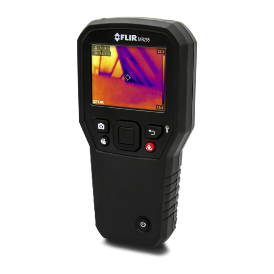
Descriptions 4.1 Product Description Figure 4.1 Front, Back, and Bottom Product Description 1. Colour Graphical Display 2. Image Capture button 3. Image Gallery button 4. Select button (centre). Press to open Menu 5. Power button 6. Laser Pointer button 7. Return and Worklight button 8. -
Page 12: Control Button Descriptions
Press to switch the Laser pointer ON. Press to capture screen image. Press to open image gallery. 4.3 Display Description Figure 4.2 MR265 Select Display Descriptions 1. Worklight icon 2. Active USB communication icon 3. Battery status icon 4. Moisture reading with sensor type icon 5. - Page 13 Descriptions 9. High end of IR image temperature range 10. Temperature scale 11. Laser pointer active icon NOTE Not all icons are represented in Figure 4–2. Other available icons are explained in their re- spective sections of this user manual. #NAS100070;...
-
Page 14: User Interface Menus
When the Select button is pressed, six menu icons appear along the bot- tom of the MR265 display. Use the left/right navigation buttons to move to a menu icon, and use the Select button to open a selected menu. Once a menu is opened, the navigation and Select buttons are used to select modes of op- erations and settings. -
Page 15: Temperature Scale Menu
Use the navigation buttons to move to the desired setting and then press Select to confirm. In Automatic mode, the MR265 automatically selects the temperature range for each thermal image, based on the highest and lowest temperatures de- tected. In Lock mode, you can ‘lock in’ a particular thermal image’s tempera- ture range and use this locked range for subsequent thermal image comparisons. -
Page 16: Image Mode Menu
User Interface Menus 5.4 Image Mode Menu Figure 5.4 Image Mode Menu The Image Mode Menu offers five sub-menus as described below. • Thermal MSX® mode: Select this mode to see the digital camera image superimposed over the thermal camera image. Use the Alignment Dis- tance menu (next section) to align the digital and thermal images. - Page 17 User Interface Menus Figure 5.6 Alignment Distance Control screens • Thermal mode: Select this mode to see the thermal image only. Figure 5.7 Thermal IR Image mode • Digital Camera mode: Select this mode to see only the visible camera image.
-
Page 18: Measurement Menu
User Interface Menus Figure 5.9 Moisture mode selection and example screen 5.5 Measurement Menu The Measurement Menu offers four sub-menus as described below. Figure 5.10 Selecting the Measurement mode from the main menu • No Measurements: Select this mode if you do not wish to see any meas- urement values or icons on the display. - Page 19 Figure 5.13 Selecting the IGM™ Moisture mode from the main menu • IGM™ Custom mode: Select this mode to view all of the measurement types on the MR265 that you enable in the Settings menu (see Section 5.8). #NAS100070; r. AB/77165/77326; en-GB...
-
Page 20: Moisture Modes Menu
User Interface Menus Figure 5.14 Selecting the IGM™ Custom mode from the main menu 5.6 Moisture Modes Menu The Moisture Mode Menu offers five sub-menus as described below. Figure 5.15 Opening the Moisture Mode menu • Material Group selection: This mode is only available when the pinless mode is selected (below). - Page 21 • MR12 mode: Select this mode when using the optional MR12 Ball Mois- ture probe accessory. The MR12 attaches to the socket on the bottom of the MR265. See Section 7.7 MR12 Ball Moisture Probe for more information. #NAS100070; r. AB/77165/77326; en-GB...
-
Page 22: Colour Menu
Figure 5.19 Selecting the MR12 (optional moisture probe) mode • Set Reference mode: This utility is only available when using the built-in pinless sensor (rear of MR265) or the remote MR12 Ball Moisture probe. After selecting the pinless mode (or the MR12 mode) and while taking a moisture measurement, select the ‘Set Reference’... -
Page 23: Settings Menu
User Interface Menus Figure 5.21 Colour palette selections 5.8 Settings Menu The Settings menu offers the following options: Figure 5.22 Selecting the ‘Settings’ mode from the main menu #NAS100070; r. AB/77165/77326; en-GB... - Page 24 User Interface Menus Figure 5.23 Settings menu items • IGM™ Custom mode: Select the readings that you wish to display when the IGM™ Custom Mode is enabled in the Measurement Menu, Section 5.5. Figure 5.24 IGM™ Custom mode selections. Pick the items to display in the IGM™ Cus- tom mode •...
- Page 25 • IR Temperature & Moisture Alarms: Set the IR Temperature Alarm to ABOVE, BELOW, or OFF. When an IR Temperature alarm is set to ABOVE or BELOW, the MR265 will alert you when the IR Temperature exceeds the high limit (temperature display turns red) or falls below the low limit (tem- perature display turns blue).
- Page 26 User Interface Menus • Device Settings: Use the Device Settings menu to set the following pa- rameters: Language, Date & Time, Screen Brightness, Lamp (Worklight) & Laser pointer, Auto Power Off, and Reset (factory default reset, internal memory formatting, and PIN calibration). These are explained below. •...
- Page 27 User Interface Menus Figure 5.29 Setting the Date and Time • Screen Brightness: Set the screen brightness as shown in the screen im- ages below. Figure 5.30 Setting the Screen Brightness • Lamp and Laser Enable/Disable: Enable or disable both the Worklight and Laser pointer.
- Page 28 (erase) the internal image memory, and to perform a PIN Calibration. To recover from a MR265 crash (display freezes), press and hold the UP and DOWN arrows for >10 seconds, until the MR265 re- boots. No data will be lost by running this procedure.
- Page 29 User Interface Menus Figure 5.34 Reset to Factory Default conditions • Format the Storage Memory: Erase all captured images from the internal memory. • PIN Calibration: When the pins are replaced in a pin probe, if the entire probe is replaced, or to simply ensure the highest accuracy, please per- form a PIN calibration.
- Page 30 User Interface Menus Figure 5.35 Viewing the Customer Support resources • Meter Information: Access this menu to see Model number, Software ver- sion, Build number, Serial number, Data storage availability, and Battery status. Figure 5.36 Checking the meter information screen •...
-
Page 31: Powering The Mr265
ON, charge the battery by connecting the meter to an AC charger using the supplied USB cable. When the MR265 is not charging, the battery status indicator is only visible from the Main Menu (press Select to access the Main Menu). -
Page 32: Moisture Measurement Operation
MR12 Ball Moisture probe, to the socket at the bottom of the meter. Other external probes are available optionally; please visit the FLIR website for details. The MR265 has a dedicated MR12 utility where you connect the probe and select the MR12 icon in the ‘Moisture Mode’ menu: Se- lect button/Moisture Mode/MR12. -
Page 33: Moisture Display Options
Moisture Measurement Operation Moisture measurements are covered in detail in the following sections. Be sure to select Pin Mode or Pinless Mode in the ‘Moisture’ menu to match the measurement type. 7.2 Moisture Display Options View moisture readings in two basic ways. 1. Moisture readings as large digits in the Moisture-only mode or 2. - Page 34 Moisture Measurement Operation Figure 7.3 Thermal mode with Moisture reading in the upper left corner • Digital Camera: This is the digital camera image only. The moisture read- ing can be seen on the upper left. Figure 7.4 Digital Camera mode with Moisture reading in the upper left corner •...
-
Page 35: Igm™ Moisture And Igm™ Custom Modes
Moisture Measurement Operation Figure 7.5 Moisture-only display mode 7.3 IGM™ Moisture and IGM™ Custom Modes In the IGM™ Moisture mode you can view a camera image with the Moisture reading appearing on the upper left. Select this mode in the menu (Measurement/IGM™... -
Page 36: Moisture Measurement Modes
Moisture Measurement Operation Figure 7.7 IGM™ Custom mode with Moisture and IR Temperature readings on upper left 7.4 Moisture Measurement Modes Press the Select button to open the Main Menu, choose the ‘Moisture’ mode , and then select from the four Moisture mode options as de- scribed below. - Page 37 MR12 mode must be selected when the optional MR12 Ball Moisture probe is used. Connect the MR12 to the accessory socket on the bottom of the MR265 (under the protective flap) and then select the MR12 from the Moisture Mode menu as shown in Figure 7–11.
-
Page 38: Pinless Moisture Measurements
Moisture Measurement Operation Figure 7.11 Selecting the MR12 (optional Ball Moisture probe) mode • Set Reference Mode ‘Set Reference’ is used to compare measurements to a stored reference value. This mode applies only to readings taken with the pinless internal sensor or the external MR12 Ball Moisture probe. -
Page 39: Pin Probe Measurements
NOTE Pin Probe Moisture Measurement Considerations The MR265 will display accurate external pin probe readings in the 7% to 30% range, de- pending on the tested material. Moisture Content readings below 6% will display as 0% for all materials and the maximum specified range is dependent on the fibre saturation point for specific species. -
Page 40: Mr12 Ball Moisture Probe (Optional)
Figure 7–11. 3. Touch the MR12 probe to the surface under test. 4. View the moisture reading on the MR265 in either the Moisture-only dis- play mode or the Thermal/Visible camera modes. Use the menus to select the display modes (Image Modes). -
Page 41: High Moisture Alarm
Moisture Measurement Operation 7.9 High Moisture Alarm 1. To access the Alarm mode use the menus (Settings/Measurement Param- eters/IR Temperature & Moisture Alarm mode). See Section 8.4 for High/ Low IR Temperature Alarm mode. Figure 7.13 Setting the Moisture Alarm 2. - Page 42 Moisture Measurement Operation 5. When the measurement exceeds the threshold, the text for the measure- ment reading will appear red in colour. Note that in the Moisture-only mode, the larger digits appear in red when the alarm limit is exceeded. See Figure 7–14 below.
-
Page 43: Thermal And Visible Camera Operation
Section 5.4 Image Mode Menu. The Thermal Camera lens is located on the back of the meter. Face the lens toward the area of interest and view the image on the MR265 display. Select the thermal image colour palette from the menu ( Colour). -
Page 44: Automatic/Lock Temperature Scaling
Thermal and Visible Camera Operation When the Laser pointer button is pressed, the Laser beam appears. Use the Laser beam and display cross-hairs to target the surfaces under test. Note that the Laser is carefully aimed to align with the cross-hairs for easier identification and targeting of objects and surfaces. -
Page 45: Digital (Visible) Camera
Thermal and Visible Camera Operation the Temperature Scale mode , press Select, and scroll to the ‘Lock’ mode ; press Select to confirm and to exit the menu. Some experimentation and fine-tuning may be required to obtain the best possible contrast. For additional programming details see Section 5.3 Temperature Scale menu. - Page 46 Thermal and Visible Camera Operation 3. Use the navigation arrows and Select button to set the Alarm (ABOVE, BELOW, or OFF) and to set the temperature limit. There is no beeper available for the Temperature alarms so the ‘No Sound’ setting cannot be changed.
-
Page 47: Capturing And Working With Images
Images can also be deleted in bulk by formatting the storage memory in the Settings menu (Settings/Device Settings/Reset Options). Images can also be deleted or moved by connecting the MR265 to a PC, see the next section. 9.4 Image Information... - Page 48 Capturing and Working with Images as you would any external storage drive. Note that on Apple™ computers, the ‘Photos’ App is not compatible with the MR265 and will generate an error message (No Photos) when opened. However the MR265 images are recog- nized in the computer’s Finder window.
-
Page 49: Field Firmware Updates
3. Select the MR265 from the second drop-down menu. 4. Select and download the firmware update file to the PC. 5. With the MR265 ON connect it to the PC via the supplied USB cable. 6. Copy the firmware update file to the MR265 root directory. -
Page 50: Maintenance
If the MR265 is not going to be used for > 3 months, it should be charged to at least 70% then stored at room temperature and recharged every 6 months. Failure to do so may result in a battery that cannot be recharged and must be serviced. -
Page 51: Specifications
Specifications 12.1 General Specifications Display QVGA (320 x 240 pixel) 2.8” 64K colour TFT graphical display Image modes Thermal, Visual, MSX® MSX® Adds visual details to full resolution thermal image Internal memory 8 G (15,000 images) Stored image format Radiometric JPEG Power supply 3.7 V, 5400 mAh Li-Po battery;... -
Page 52: Thermal Imaging Specifications
Specifications 12.2 Thermal Imaging Specifications Thermal imaging camera FLIR Lepton®, microbolometer FPA (focal plane array) Image calibration Automatic (with lock-scale option: see Tempera- ture Scale option from the Main Menu) Thermal image resolution 160(W) x 120(H) pixels 8~14µm Spectral response Field of view 57°... -
Page 53: Visible Spectrum Camera Specifications
Specifications 3. See Note 1. 12.4 Visible Spectrum Camera Specifications 2M pixels Camera resolution Focus Fixed Field of view 83° (70.5° Horizontal x 56° Vertical) 12.5 Safety Specifications General Safety CE/EN/UL/CSA/PSE 61010 Environmental Safety REACH Regulation EC 1907/2006 RoHS2 Directive 2011/65/EC WEEE Directive 2012/19/EC JIS C 6802:2011 laser directive IEC 60825-1 class II laser directive... -
Page 54: Appendices
Appendices 13.1 Material Groups 13.1.1 Common names of timbers (BS888/589:1973) with MR265 Group Numbers NOTE Use Group 9 for building materials: plywood, drywall, and oriented strand board (OSB). Use Group 10 for brick, cement screed, and concrete. Use Group 11 for cement mortar, anhydrite screed, lime mortar, and plaster. - Page 55 Appendices Beech, European Kuroka Pine, Ponderosa Berlina Larch, Pine, Radiata European Pine, Red Binvang Larch, Japanese Birch, European Larch, Western Pine, Scots Birch, Yellow Lime Pine, Sugar Bisselon Loliondo Pine, Yellow Poplar, Black Bitterwood Mahogany, African Blackbutt Mahogany, Pterygota, West Indian African Bosquiea Makore...
- Page 56 Appendices Muninga Cypress, Japa- Silky Oak, nese (18-28% African Cypress, Japa- Musine Silky Oak, nese (8-18%mc) Australian Dahoma Musizi Spruce, Japa- nese (18-28% Danta Myrtle, Spruce, Japa- Tasmanian nese (8-18% Douglas Fir Naingon Spruce, Nor- (European) Elm, English Oak, American Spruce, Sitka Elm, Japanese Oak, American...
-
Page 57: Botanical Names Of Timbers
Appendices Panga Panga Walnut, Gum, Saligna Queensland Gum, Southern Persimmon Wandoo Gum, Spotted Pillarwood Wawa Whitewood 13.1.2 Botanical names of timbers Material Group Material Group Material Group Abies alba Eucalyptus Picea jezoensis acmenicides (8-18%mc) Picea sitchensis Abies grandis Eucalyptus crebra Abies procera Eucalyptus Pinus caribaea... - Page 58 Appendices Fraxinus Pinus thunbergii Amblygonocar- pus andogensis Americana Amblygonocar- Fraxinus Pipadeniastrum pus obtusungulis excelsior africanum Fraxinus Piptadenia Araucaria angustifolia japonicus africana Araucaria bidwilli Fraxinus Podocarpus mardshurica dacrydiodes Podocarpus Araucaria Gonystylus cunninghamii spicatus macrophyllum Berlinia Podocarpus Gossweiloden- grandiflora totara dron balsamiferum Berlinia spp Populus spp Gossypiosper-...
- Page 59 Appendices Ricinodendron Cassipourea Larix kaempferi elliotii heudelotti Cassipourea Larix leptolepis Sarcocephalus melanosana diderrichii Larix Castanea sutiva Scottellia occidentalis coriacea Liquidamper Cedrela odorata Sequoia styraciflua sempervirens Lovoa klaineana Ceratopetalum Shorea spp apetala Chamaecyparis Lovoa Sterculia spp (18-28%mc) trichiloides rhinopetala Maesopsis Chamaecyparis Swietenia eminii spp (8-18%mc)
-
Page 60: Wme Table (% Wood Moisture Equivalent)
Appendices Tilia vulgaris Dracontomelium Olea mangiferum hochstetteri Dryobanalops Triploehiton Olea welwitschii scleroxylon Dyera costulata Palaquium spp Tsuga heterophylia Endiandra Paulownia Ulmus palmerstoni tomentosa americana Entandrophrag- Pericopsis elata Ulmus procera ma angolense Picaenia excelsa Ulmus thomasii Entandrophrag- ma cylindricum Entandrophrag- Picea abies Xylia ma utile dolabriformis... - Page 61 Appendices 20.8 23.5 18.5 17.6 16.8 19.1 22.3 18.3 21.5 24.5 19.3 18.3 17.4 19.7 23.2 19.1 22.9 26.4 20.2 19.8 18.6 21.2 25.3 19.9 23.5 27.4 20.8 20.4 25.8 20.5 24.2 27.8 21.2 19.4 22.7 26.3 ≈23 25.3 22.4 22.3 20.1 23.9...
-
Page 62: Limited 10-Year Warranty
Limited 10–Year Warranty This product is protected by FLIR’s Limited 10-Year Warranty. Visit www.flir.com/testwarranty to read the Limited 10-Year Warranty document. #NAS100070; r. AB/77165/77326; en-GB... -
Page 63: Customer Support
Customer Support Repair, Calibration, and Technical Support: https://support.flir.com. Customer Support Telephone List: https://support.flir.com/contact #NAS100070; r. AB/77165/77326; en-GB... - Page 64 #NAS100070; r. AB/77165/77326; en-GB...
- Page 66 Customer support http://support.flir.com Copyright © 2021, FLIR Systems, Inc. All rights reserved worldwide. Disclaimer Specifications subject to change without further notice. Models and accessories subject to regional market considerations. License procedures may apply. Products described herein may be subject to US Export Regulations.
Need help?
Do you have a question about the MR265 and is the answer not in the manual?
Questions and answers
i lost my charger i need to buy one