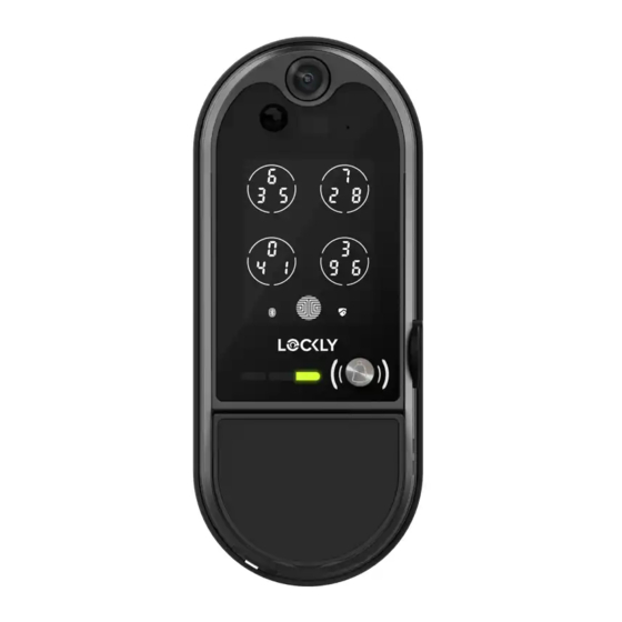
Lockly VISION ELITE Installation Manual
Deadbolt edition
Hide thumbs
Also See for VISION ELITE:
- User manual (40 pages) ,
- Installation manual (24 pages) ,
- Start here (5 pages)
Advertisement
Quick Links
Advertisement

Related Manuals for Lockly VISION ELITE


Summary of Contents for Lockly VISION ELITE
- Page 1 INSTALLATION GUIDE DEADBOLT EDITION...
- Page 2 Go to Lockly.com/installation to download the latest version of this installation guide. Scan the code on your phone to watch step-by-step video installation.
- Page 3 Lockly Vision Elite up and running. ™ Installation generally takes less than 30 minutes. If you have any questions please reference our online support at: Lockly.com/support or call (669) 500-8835 for help. Reference installation parts overview foldout on back page...
- Page 4 Flathead Screwdriver Tape measure or ruler Before installation and setup of Lockly Vision Elite, it is important to charge the lithium battery for a full 12 hours. A sufficiently charged battery is necessary to establish connection between the lock and the app. We strongly recommend ensuring the battery is fully charged before proceeding with the installation process.
- Page 5 Cross-bore 2-⅛" (54mm) REPLACE YOUR EXISTING OLD DEADBOLT. USE THE INCLUDED DEADBOLT DESIGNED AND OPTIMIZED FOR LOCKLY SMART LOCKS. The included deadbolt integrates a smart door sensor to detect the open / closed status of your door. Depending on the gap between door and door frame, you may need to increase the depth of the groove.
- Page 6 Step 1 ADJUST DEADBOLT AND INSTALL The deadbolt defaults to 2-3/4 "(70mm) backset which is measured from the center of the door hole to the door edge. If the deadbolt slot is aligned to the center of the door hole, proceed to skip the following steps and proceed to the next page. 2-3/4"...
- Page 7 Step 1 ADJUST DEADBOLT AND INSTALL continued Extend the deadbolt by inserting a flat-head Insert the deadbolt into the door edge, screwdriver into the slot and turning clockwise. make sure that the right side is up and the slot is in the vertical position. Secure with 2 screws.
- Page 8 Step 2 INSTALLING EXTERIOR ASSEMBLY (B) 2. Make sure the torque blade is in a 1. Peel off protective film from the vertical position with the deadbolt adhesive strips extended. Vertical Extended 3. Follow the diagram and guide the cable to pass through under the deadbolt by gently pulling it from the inside to ensure it remains straight and not bent.
- Page 9 Step 3 INSTALLING INTERIOR ASSEMBLY (G) 1. Peel off protective film from the adhesive strips on the back of the mounting plate . Guide connection cables through the hole and secure to the notch on the lower left corner. Align the mounting plate onto door and firmly press to secure it in place.
- Page 10 Step 3 INSTALLING INTERIOR ASSEMBLY (G) continued 4. Plug the cables coming through mounting plate into the interior assembly shown, route to the right of interior assembly Do not touch pins inside* Call our Customer Care Hotline (669) 500-8835, for help if the pins are not centered or bent.
- Page 11 Step 3 INSTALLING INTERIOR ASSEMBLY (G) continued 5. Insert the connected cables C1+C2 D1+D2 into the grooves on the side. Make sure the foam pads attached to the cables are secured to prevent the cables from moving. C1+C2 D1+D2 Tuck the cables behind the cable rail of the interior assembly.
- Page 12 Step 3 INSTALLING THE INTERIOR ASSEMBLY (G) continued 6. Before placing the interior 7. Place the interior assembly 8. Secure the interior assembly assembly onto the mounting against the mounting plate to mounting plate with 2 plate, ensure the thumb turn and make sure the torque screws.
-
Page 13: Installing Battery
Step 4 INSTALLING BATTERY Hook for battery (Optional) 1. With door open and deadbolt fully extended, insert lithium battery. Make sure to securely hook the battery on the provided slot of the interior assembly. (Optional) Tighten the screw on the right side. - Page 14 Step 5 INSTALLING STRIKE PLATE Use the supplied door strike plate (L) which has the built-in door sensor magnet. If your door gap is larger than 5mm, it is recommended to install Strike Spacer to lessen the gap to ensure the normal operation of the door sensor.
- Page 15 Step 6 SETUP THE HUB To enable video doorbell, live monitoring and voice control with Hey Google and Alexa, you will need to setup the included Vision Connect WI-Fi hub with the Lockly Vision Elite deadbolt ™ smart lock + video doorbell.
- Page 16 Step 7 LOCKLY APP & UNIQUE ACTIVATION CODE Before setting up Vision Connect Hub download the Lockly app on your smartphone. It’s required to finish and setup the connection between hub and lock. Scan, visit app store, or go to Lockly.com/app Additionally, you'll need the Activation Card with unique pre-paired QR code to your lock.
-
Page 17: Location Guidelines
Sometimes distances between hub and lock can vary due to circumstances. If you are having difficulty setting up optimal range of 100/ft or less, we’re here to help. Call our customer care team: (669) 500 8835, or visit Lockly.com/help for suggestions and troubleshooting tips. - Page 18 Step 9 VISION CONNECT HUB SETUP Ensure the TF card that comes with Connect LAN cable to closest Wi-Fi router Vision Connect is properly inserted. to the Lockly Vision Elite lock (<100ft). ™ Always keep the Antenna on UP position...
- Page 19 Step 10 PAIR VISION LOCK TO APP Launch the Lockly App and select "add a new device", then select Vision. You will be prompted to scan the QR code from the Activation Card or Vision Connect Hub (located at the bottom).
- Page 20 VISION CONNECT STATUS & TROUBLESHOOTING STATUS LED INDICATORS After connecting LAN cable and Power ON/ power adapter, wait for 2mins for Solid red ON Successfully paired Vision Connect to self calibrate. Yellow slow blinking Network connected READY TO CONNECT If you experience any of the following, power down and disconnect hub, repeat connection process Pairing / Network Red slow blinking NOT yet connected...
-
Page 21: Voice Control
Amazon Alexa Skill or Lockly Action on Google. In Google Home or Amazon Alexa app, add Lockly skill for Alexa or Lockly Action on Google, then follow on screen instructions. See full list of commands, help videos, or troubleshooting your Lockly at https://Lockly.com/help... - Page 22 FCC Warning: This device complies with Part 15 of the FCC Rules. Operation is subject to the following two conditions: (1) This device may not cause harmful interference, and (2) this device must accept any interference received, including interference that may cause undesired operation. NOTE 1: This equipment has been tested and found to comply with the limits for a Class B digital device, pursuant to part 15 of the FCC Rules.
- Page 23 L’émetteur/récepteur exempt de licence contenu dans le présent appareil est conforme aux CNR d’Innovation, Sciences et Développement économique Canada applicables aux appareils radio exempts de licence. L’exploitation est autorisée aux deux conditions suivantes: 1. L’appareil ne doit pas produire de brouillage; 2.
- Page 24 Vision Connect LAN Cable Power Plug TF Card Activation Card KM3x6mm Screw Pin Key Activation Card SAVE Lockly Vision Elite can be fitted for both right swing doors and left swing doors. ™ Need help? Email: help@Lockly.com | Support: +1(669) 500-8835...
- Page 25 Bluetooth SIG, Inc. , and any use of such marks by Lockly is under license. Other trademarks and trade names are those of their respective owners. Google, Android, Google Play and Google Home are trademarks of Google LLC.
Need help?
Do you have a question about the VISION ELITE and is the answer not in the manual?
Questions and answers