Advertisement
Quick Links
Advertisement

Related Manuals for Lockly DEADBOLT EDITION PGD1128


Summary of Contents for Lockly DEADBOLT EDITION PGD1128
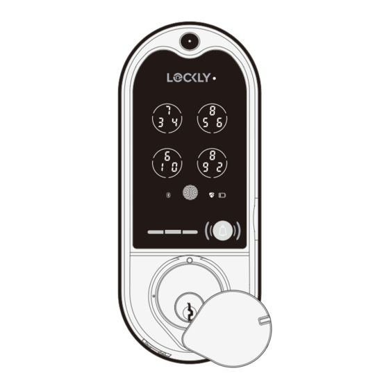
- Page 1 VISION ™ SMART LOCK + VIDEO DOORBELL INSTALLATION MANUAL DEADBOLT EDITION...
- Page 2 C A U T I O N Contains Electrostatic- sensitive (ESD) parts. Avoid touching with bare hands. For best practices, (1) ground yourself by (a) touching a metal surface to discharge any ESD you might have; (b) changing clothes if you are sparky; and (2) avoid touching the internal pins.
- Page 3 Strike Plate Dust Box Wired Sensor Sensor Magnet Vision Connect LAN Cable Power Plug TF Card Activation Card LOCK SERIAL PGDXXXXXXXXX ACTIVATION CODE XXXXXXXX SCAN & SAVE Lockly Vision™ can be fitted for both right swing doors and left swing doors.
- Page 5 STEP 1: PREPARE DOOR FOR INSTALLATION 1.1: To complete installation, you would need the following: Flathead Screwdriver Phillips Screwdriver Ruler 1.2: Prepare door and remove existing lock. If necessary, use provided Installation Template to prepare door. 2-⅜" (60mm) or 2-¾" (70mm) 1-⅜"...
- Page 6 STEP 2. ADJUST DEADBOLT AND INSTALL 2.1 Deadbolt slit hole must be aligned to the center of the door hole. If not adjust as shown below: 2.1.1 Wear gloves during adjustment Deadbolt at 2-3/4" (70mm) to prevent pinching your hands (default shipping status) extend I.
- Page 7 STEP 2. ADJUST DEADBOLT AND INSTALL 2.2 Extend the deadbolt by inserting a 2.3 Insert the Deadbolt to the edge flat head screwdriver on the slit hole or door hole, make sure that its right side by pushing the crank towards the metal up and the slit hole is in vertical position, face plate.
- Page 8 STEP 3. INSTALLING THE EXTERIOR ASSEMBLY (B) 3.1: Check the Exterior Assembly 3.2: Before placing the exterior assembly on the alignment to your door hole and door, make sure the torque blade is in vertical deadbolt, before you peel off position and the deadbolt is extended.
- Page 9 STEP 4. INSTALLING THE INTERIOR ASSEMBLY (G) 4.1: Check the mounting plate 4.2: Place the mounting plate on the alignment to your door hole before interior side of the door. Guide the cable you peel of the cover off the to the opening ear on the side of mounting adhesive strip.
- Page 10 STEP 5. PREPARING DOOR SENSORS FOR INSTALLATION > Do not install the door sensors yet. You will install the sensors on STEP 8 Lockly Vision comes with a pre-installed door sensors consisting of two parts: ™ Part P - Wired Sensor Part Q - Sensor Magnet Make sure you install the Door Sensors indoors on a clean and dry surface.
- Page 11 STEP 5. PREPARING DOOR SENSORS FOR INSTALLATION When you are installing the door sensors, make sure the arrow of the wired sensor (P) is placed next to the arrow of the sensor magnet (Q) as close as possible. 2-3/8" (60mm) <...
- Page 12 STEP 5. PREPARING DOOR SENSORS FOR INSTALLATION 5.1 The Interior assembly comes with 5.2 For left swing doors, re-route the door pre-installed wired door sensor for right sensor wire through the side channel. Pull swing doors with 2 ¾" (70mm) backset*. the foam pad (f) then re-insert to secure Discard the excess part (e) for doors with the wire.
- Page 13 STEP 6. INSTALLING THE INTERIOR ASSEMBLY (G) 6.1 From the cable coming from the external assembly (PART B), plug the small cable con- nector x to y and screw tightly as shown: Connect and Screw * Call our Customer Service Hotline (669) Do not 500-8835, if the pins are touch the...
- Page 14 STEP 6. INSTALLING THE INTERIOR ASSEMBLY (G) 6.4 Place the interior assembly against the 6.3 Before placing the interior mounting plate and make sure the torque assembly to the mounting plate, blade is inserted to the thumb turn shaft. ensure the thumb turn is vertical. MAKE SURE IT IS IN THE Torque Blade Thumb turn shaft...
-
Page 15: Step 7. Installing Batteries
STEP 7. INSTALLING BATTERIES 7.1: While the door is open and deadbolt is extended, place the ribbon inside the compartment and insert only 3 batteries at the bottom layer with correct polarities. Ensure the bolt is FULLY EXTENDED Press and hold the program button before inserting the 4th battery. - Page 16 NOTE: The arrows must be aligned or as closed as possible (less than 3/4"). If needed, adjust the position of the sensor magnet using provided foam pads to ensure the LOCKLY logo blinks red when door opens or closes. ®...
- Page 17 STEP 9: INSTALLING THE DOOR STRIKE Install the door strike. Install the door strike to your door frame and proceed to the last step of installation of your new lock. You may use our supplied door strike or use your existing door strike as long as the deadbolt moves smoothly in and out of the door strike.
- Page 18 STEP 10. VISION CONNECT SETUP Congratulations, you are a few steps away from completing the setup of Lockly Vision To enable video doorbell, add Live Monitoring and voice control with Google Assistant or Amazon Alexa, you will need to setup the Vision Connect included in the box.
- Page 19 Select a secure location to setup the Vision Connect. Choose the nearest Wi-Fi router to directly plug the LAN cable that comes with Lockly Vision™ The selected location is suggested to be less than <50 feet away from Lockly Vision™...
- Page 20 STEP 10. VISION CONNECT HUB SETUP 10.2: 10.3: Ensure the TF card that comes Ensure to plug the LAN cable to with Vision Connect is properly inserted. the nearest Wi-Fi router to Lockly Vision ™ 1ft cable (S) Included TF card is included 10.4: 10.5:...
- Page 21 Vision Connect LED INDICATOR STATUS Troubleshooting Guide After you plug in the LAN cable and Power adapter, and wait for 2mins Power ON/ for Vision Connect to self calibrate. Solid Red ON Successfully paired Yellow Slow Blinking Network Connected READY TO CONNECT Pairing | Network Red Slow Blinking NOT yet Connected...
- Page 22 2. . Allow your mobile phone to receive push notification 3. . Send in-app feedback if you encountered any issu while using the App. 4. . Ensure your Lockly® App has the most updat firmware. For more info, visit: http://www.support.lockly.com/faq/firmware-update/...
- Page 23 ” Skill for Alexa or the Action for Google Assistant ® then follow on screen instructions to finish setup. For a full list of commands, help videos or to troubleshoot your Secure Link Wi-Fi Hub visit us at https://lockly.com/help Google, Android and Google Play are trademarks of Google LLC.
- Page 24 Certified FCC Warning: This device complies with Part 15 of the FCC Rules. Operation is subject to the following two conditions: (1) This device may not cause harmful interference, and (2) this device must accept any interference received, including interference that may cause undesired operation. NOTE 1: This equipment has been tested and found to comply with the limits for a Class B digital device, pursuant to part 15 of the FCC Rules.
- Page 25 (1) This device may not cause interference. (2) This device must accept any interference, including interference that may cause undesired operation of the device. L’émetteur/récepteur exempt de licence contenu dans le présent appareil est conforme aux CNR d’Innovation, Sciences et Développement économique Canada applicables aux appareils radio exempts de licence.
- Page 26 VISION ™ We’re here to help! help@lockly.com https://lockly.com/help IMPGD1128FPW20200428...
- Page 28 VISION ™ For the latest version of this manual, please visit the link below: http://lockly.com/help...
Need help?
Do you have a question about the DEADBOLT EDITION PGD1128 and is the answer not in the manual?
Questions and answers