Table of Contents
Advertisement
Quick Links
www.ti.com
User's Guide
TPS7A14EVM Evaluation Module
SBVU073A – NOVEMBER 2021 – REVISED JUNE 2023
Submit Document Feedback
ABSTRACT
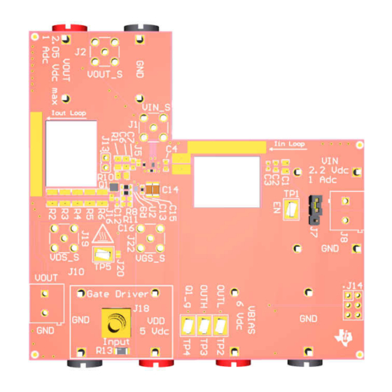
Figure 1-1. TPS7A14EVM-058 Evaluation Module
Figure 1-2. TPS7A14EVM-095 Evaluation Module
Copyright © 2023 Texas Instruments Incorporated
TPS7A14EVM Evaluation Module
1
Advertisement
Table of Contents

Subscribe to Our Youtube Channel
Related Manuals for Texas Instruments TPS7A14EVM


Summary of Contents for Texas Instruments TPS7A14EVM
-
Page 1: Figure 1-1. Tps7A14Evm-058 Evaluation Module
User's Guide TPS7A14EVM Evaluation Module ABSTRACT Figure 1-1. TPS7A14EVM-058 Evaluation Module Figure 1-2. TPS7A14EVM-095 Evaluation Module SBVU073A – NOVEMBER 2021 – REVISED JUNE 2023 TPS7A14EVM Evaluation Module Submit Document Feedback Copyright © 2023 Texas Instruments Incorporated... -
Page 2: Table Of Contents
Figure 1-1. TPS7A14EVM-058 Evaluation Module........................Figure 1-2. TPS7A14EVM-095 Evaluation Module........................Figure 2-1. TPS7A14EVM-058 Turn On............................Figure 2-2. TPS7A14EVM-058 With Current Probes Attached....................Figure 2-3. TPS7A14EVM-058 Load Transient Results: 1-mA to 950-mA Load Step..............7 Figure 2-4. TPS7A14EVM-058 Load Transient Results: 950-mA to 1-mA Load Step..............7 Figure 3-1. -
Page 3: Introduction
TPS7A14EVM-058 contains one TPS7A14 LDO voltage regulator in the DSBGA package and the TPS7A14EVM-095 contains one TPS7A14 LDO voltage regulator in WSON package . An optional load transient circuit is also included to assist the user with high-speed load transient testing. An input current loop is included that allows fast measurements of the input current. -
Page 4: Tps7A14 Ldo Operation
TPS7A14 LDO after VIN is applied. Figure 2-1 shows the result of the TPS7A14EVM-058 during turn on. The blue trace is the enable voltage, and the red trace is the output voltage. Figure 2-1. TPS7A14EVM-058 Turn On TPS7A14EVM Evaluation Module SBVU073A –... -
Page 5: Figure 2-2. Tps7A14Evm-058 With Current Probes Attached
The slots were sized to fit most current probes, such as the LeCroy AP015 or CP031 current probes. Figure 2-2. TPS7A14EVM-058 With Current Probes Attached The user has two options for providing a DC load on the output of the TPS7A14. J10 can be used to place a DC load that flows through the current sense path on the output of the LDO. -
Page 6: Optional Load Transient Circuit Operation
2.4 Optional Load Transient Circuit Operation The TPS7A14EVM-058 and TPS7A14EVM-095 evaluation modules contains an optional high-performance load transient circuit to allow efficient testing of the TPS7A14 LDO load transient performance. To use the optional load transient circuit, install the correct components in accordance with the application. Modify the input and output capacitance connected to the TPS7A14 LDO to match the expected operating conditions. -
Page 7: Figure 2-3. Tps7A14Evm-058 Load Transient Results: 1-Ma To 950-Ma Load Step
Setup Figure 2-3. TPS7A14EVM-058 Load Transient Figure 2-4. TPS7A14EVM-058 Load Transient Results: 1-mA to 950-mA Load Step Results: 950-mA to 1-mA Load Step SBVU073A – NOVEMBER 2021 – REVISED JUNE 2023 TPS7A14EVM Evaluation Module Submit Document Feedback Copyright © 2023 Texas Instruments Incorporated... -
Page 8: Board Layout
Figure 3-12 illustrate the board layout for the TPS7A14EVM-095 PCB The TPS7A14EVM-058 and TPS7A14EVM-095 dissipate power, which can cause some components to experience an increase in temperature. The TPS7A14 LDO, LMG1020YFFR gate driver, and pulsed resistors R2, R3, R4, R5, and R6 are most at risk of raising to a high junction temperature during normal operation. -
Page 9: Figure 3-5. Tps7A14Evm-058 Bottom Layer Routing
Figure 3-6. TPS7A14EVM-058 Bottom Assembly Figure 3-5. TPS7A14EVM-058 Bottom Layer Layer and Silk Screen Routing Figure 3-7. TPS7A14EVM-095 Top Assembly Layer Figure 3-8. TPS7A14EVM-095 Top Layer Routing and Silk Screen SBVU073A – NOVEMBER 2021 – REVISED JUNE 2023 TPS7A14EVM Evaluation Module Submit Document Feedback Copyright ©... -
Page 10: Figure 3-9. Tps7A14Evm-095 Layer 2
Board Layout www.ti.com Figure 3-9. TPS7A14EVM-095 Layer 2 Figure 3-10. TPS7A14EVM-095 Layer 3 Figure 3-12. TPS7A14EVM-095 Bottom Assembly Figure 3-11. TPS7A14EVM-095 Bottom Layer Layer and Silk Screen Routing TPS7A14EVM Evaluation Module SBVU073A – NOVEMBER 2021 – REVISED JUNE 2023 Submit Document Feedback... -
Page 11: Tps7A14Evm Schematic
VDD Re comme nde d Ma x = 5.4V 0.015uF J 20 0.1uF 10uF 10uF LMG1020YFFR 49.9 J 21 100V 100V Figure 4-1. TPS7A14EVM-058 Schematic SBVU073A – NOVEMBER 2021 – REVISED JUNE 2023 TPS7A14EVM Evaluation Module Submit Document Feedback Copyright © 2023 Texas Instruments Incorporated... -
Page 12: Figure 4-2. Tps7A14Evm-095 Schematic
J 20 0.1uF 10uF 10uF LMG1020YFFR 49.9 J 21 100V 100V R13 to be replaced with RMCF1206FT49R9 Figure 4-2. TPS7A14EVM-095 Schematic TPS7A14EVM Evaluation Module SBVU073A – NOVEMBER 2021 – REVISED JUNE 2023 Submit Document Feedback Copyright © 2023 Texas Instruments Incorporated... -
Page 13: Bill Of Materials
TPS7A14EVM Schematic 5 Bill of Materials Table 5-1 shows the bill of materials for the TPS7A14EVM-058 and TPS7A14EVM-095. Table 5-1. Bill of Materials Designator Quantity Value Description PackageReferen PartNumber Manufacturer Alternate Alternate PartNumber Manufacturer LP058 EVM LP095 EVM !PCB1... - Page 14 ERJ-6GEY0R00V Panasonic Grade 0, 0805 R11, R12 RES, 0, 1%, 0.1 W, AEC-Q200 Grade RMCF0603ZT0R0 Stackpole 0, 0603 Electronics Inc TPS7A14EVM Evaluation Module SBVU073A – NOVEMBER 2021 – REVISED JUNE 2023 Submit Document Feedback Copyright © 2023 Texas Instruments Incorporated...
- Page 15 Bill of Materials 5 Bill of Materials Table 5-1 shows the bill of materials for the TPS7A14EVM-058 and TPS7A14EVM-095. Table 5-1. Bill of Materials Designator Quantity Value Description PackageReferen PartNumber Manufacturer Alternate Alternate PartNumber Manufacturer LP058 EVM LP095 EVM...
- Page 16 ERJ-6GEY0R00V Panasonic Grade 0, 0805 R11, R12 RES, 0, 1%, 0.1 W, AEC-Q200 Grade RMCF0603ZT0R0 Stackpole 0, 0603 Electronics Inc TPS7A14EVM Evaluation Module SBVU073A – NOVEMBER 2021 – REVISED JUNE 2023 Submit Document Feedback Copyright © 2023 Texas Instruments Incorporated...
-
Page 17: Revision History
NOTE: Page numbers for previous revisions may differ from page numbers in the current version. Changes from Revision * (November 2021) to Revision A (June 2023) Page • Added TPS7A14EVM-095 Evaluation Module figure..................• Added LP095 to Device Information table ......................•... - Page 18 STANDARD TERMS FOR EVALUATION MODULES Delivery: TI delivers TI evaluation boards, kits, or modules, including any accompanying demonstration software, components, and/or documentation which may be provided together or separately (collectively, an “EVM” or “EVMs”) to the User (“User”) in accordance with the terms set forth herein.
- Page 19 www.ti.com Regulatory Notices: 3.1 United States 3.1.1 Notice applicable to EVMs not FCC-Approved: FCC NOTICE: This kit is designed to allow product developers to evaluate electronic components, circuitry, or software associated with the kit to determine whether to incorporate such items in a finished product and software developers to write software applications for use with the end product.
- Page 20 www.ti.com Concernant les EVMs avec antennes détachables Conformément à la réglementation d'Industrie Canada, le présent émetteur radio peut fonctionner avec une antenne d'un type et d'un gain maximal (ou inférieur) approuvé pour l'émetteur par Industrie Canada. Dans le but de réduire les risques de brouillage radioélectrique à...
- Page 21 www.ti.com EVM Use Restrictions and Warnings: 4.1 EVMS ARE NOT FOR USE IN FUNCTIONAL SAFETY AND/OR SAFETY CRITICAL EVALUATIONS, INCLUDING BUT NOT LIMITED TO EVALUATIONS OF LIFE SUPPORT APPLICATIONS. 4.2 User must read and apply the user guide and other available documentation provided by TI regarding the EVM prior to handling or using the EVM, including without limitation any warning or restriction notices.
- Page 22 Notwithstanding the foregoing, any judgment may be enforced in any United States or foreign court, and TI may seek injunctive relief in any United States or foreign court. Mailing Address: Texas Instruments, Post Office Box 655303, Dallas, Texas 75265 Copyright © 2023, Texas Instruments Incorporated...
- Page 23 TI products. TI’s provision of these resources does not expand or otherwise alter TI’s applicable warranties or warranty disclaimers for TI products. TI objects to and rejects any additional or different terms you may have proposed. IMPORTANT NOTICE Mailing Address: Texas Instruments, Post Office Box 655303, Dallas, Texas 75265 Copyright © 2023, Texas Instruments Incorporated...
Need help?
Do you have a question about the TPS7A14EVM and is the answer not in the manual?
Questions and answers