Table of Contents
Advertisement
Quick Links
PROFESSIONAL MEDICAL PRODUC TS
GIMA VITAL SIGNS MONITORS
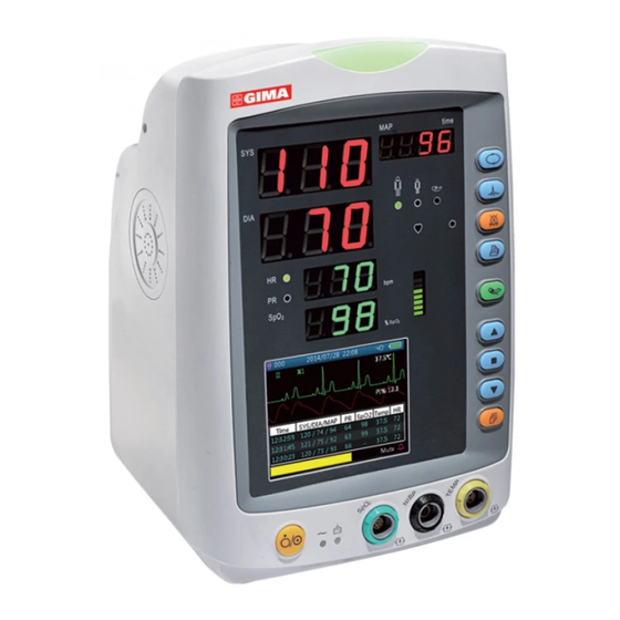
VITAL PRO (SNET)
PC-900 (GIMA 35124)
Shenzhen Creative Industry Co., Ltd.
Floor 5, BLD 9, BaiWangxin High-Tech Industrial Park,
Songbai Road, Xili Street, Nanshan District,
518110 Shenzhen, P.R. China
Made in China
Shanghai International Holding Corp. GmbH (Europe)
Eiffestrasse 80, 20537 Hamburg - Germany
Imported by:
Gima S.p.A.
Via Marconi, 1 - 20060 Gessate (MI) Italy
gima@gimaitaly.com - export@gimaitaly.com
www.gimaitaly.com
95%
%
-20˚C
10%
107,4kPa
50kPa
+60˚C
0123
IPX2
Advertisement
Table of Contents

Subscribe to Our Youtube Channel
Related Manuals for Gima VITAL PRO SNET


Summary of Contents for Gima VITAL PRO SNET
- Page 1 PROFESSIONAL MEDICAL PRODUC TS GIMA VITAL SIGNS MONITORS VITAL PRO (SNET) PC-900 (GIMA 35124) Shenzhen Creative Industry Co., Ltd. +60˚C 0123 Floor 5, BLD 9, BaiWangxin High-Tech Industrial Park, Songbai Road, Xili Street, Nanshan District, 518110 Shenzhen, P.R. China -20˚C...
- Page 2 This Manual is written and compiled in accordance with the IEC 60601-1(Medical electrical equipment Part1: General requirements for safety)and MDD 93/42/EEC. It complies with both international and enterprise standards and is also approved by State Technological Supervision Bureau. The Manual is written for the current Vital Signs Monitor. The Manual describes, in accordance with the Vital Signs Monitor’s features and requirements, main structure, functions, specifications, correct methods for transportation, installation, usage, operation, repair, maintenance and storage, etc.
- Page 3 Instructions to User Dear Users, Thank you very much for purchasing our product. Please read the following information very carefully before using this device. Read these instructions carefully before using this monitor. These instructions describe the operating procedures to be followed strictly. Failure to follow these instructions can cause monitoring abnormity, equipment damage and personal injury.
- Page 4 M DO NOT take blood pressure measurement from a limb receiving ongoing transfusion or intubation or skin lesion area, otherwise, damages may be caused to the limb. M Continuous use of SpO sensor may result in discomfort or pain, especially for those with micro-circulatory problem.
-
Page 5: Table Of Contents
Table of Contents Chapter 1 Overview ................................1 1.1 Features................................1 1.2 Product Name and Model ............................ 1 1.3 Intended Use ................................ 1 1.4 Safety ................................... 1 Chapter 2 Operating Principle ............................2 2.1 Overall Structure..............................2 2.2 Conformation ............................... 2 Chapter 3 Installation and Connection .......................... - Page 6 6.2 TEMP Monitoring.............................. 46 6.3 NIBP Monitoring ............................... 46 6.4 SpO Monitoring..............................46 6.5 Pulse Rate monitoring ............................46 6.6 Data Recording ..............................46 6.7 Other Technical Specifications .......................... 47 6.8 Operating Environment ............................. 47 6.9 Classification ..............................47 6.10 Other Technical Information ..........................47 6.10.1 Additional description for ECG monitoring ..................
-
Page 7: Chapter 1 Overview
² Option of built-in printer to print out waveform, and text information. Note: The monitor you purchased may not cover all the mentioned functions according to its configuration. 1.2 Product Name and Model GIMA VITAL PRO MONITOR - VITAL PRO (SNET) Name: 1.3 Intended Use This Monitor is a multi-functional instrument designed for monitoring the vital physiological signs of adult and pediatric patients. -
Page 8: Chapter 2 Operating Principle
Figure 2.1 2.2 Conformation The Gima Vital Pro Monitor is a product with modular design, consisting of an ECG module (Optional), NIBP module, module, temperature module, main control unit, printer module (Optional), display panel, and power supply module etc. and the related accessories for ECG, NIBP, SpO and temperature measurement. -
Page 9: Chapter 3 Installation And Connection
Chapter 3 Installation and Connection 3.1 Appearance 3.1.1 Front Panel The Gima Vital Pro Monitor with ECG function Figure 3.1B Front panel illustration for monitor (with ECG function) Description: 1. " "Alarm indicator Indicator Alarm Level Color Red flashing High priority alarm... - Page 10 4. " ": heart beat indicator. 5. HR/PR: display of heart rate / pulse rate; unit: bpm. Heart rate is priority to be displayed. 6. SpO : display of SpO value; Unit: “%”. 7. " ": LCD panel 8. " ": Power button: Long pressing power button to start or shut off the monitor;...
-
Page 11: Side Panel
20. " " Up: shifts cursor forward/upward 21. " " OK: In setting menu, press it to confirm selection or modification; On history record screen, long pressing this key to open up delete data dialogue box; On monitoring screen, short press to freeze/unfreeze ECG waveform. -
Page 12: Rear Panel
3.1.3 Rear Panel Figure 3.4 Rear Panel The rear panel of the monitor is as shown in figure 3.4. Form 3-1 Real panel Symbols and descriptions Symbol Description Symbol Description Warning-- Refer to User Manual FUSE 2XT1.0AL Fuse holder USB connector Equipotential terminal Nurse-call connector Fuse specification: T1.0AL/250V φ5*20mm... -
Page 13: Underside Of The Monitor
3.1.4 Underside of the Monitor Battery cover Figure 3.5 Underside of the monitor 3.2 Battery Installation 1. Ensure that the monitor is not connected to AC power supply and is turned off. 2. Open the battery cover and move the locking bar aside. 3. - Page 14 Battery cable Battery Battery cable plug Locking bar Battery power socket Battery power cable Battery cover tether Battery cover Figure 3.6 Battery Installation Warning : 1. To avoid battery damage always remove battery(s) before shipping or storage. 2. It is recommended to use the battery specified by the manufacturer. 3.
-
Page 15: Installation
3.3 Installation 3.3.1 Opening the Package and Check 1. Open the package, take out the monitor and accessories from the box carefully and place them on a safe sand table and surface. 2. Open the accompanying document to sort the accessories according to the packing list. u Inspect the monitor for any mechanical damages u Check all the accessories for any scratch or deformity, especially on connectors, wire and probe parts ☞... - Page 16 2. Select electrodes to be used. Use only one type of electrode on the same patient to avoid variations in electrical resistance. For ECG monitoring, it is strongly recommended to use silver/silver chloride electrodes. When dissimilar metals are used for different electrodes, the electrodes may be subject to large offset potentials due to polarization.
- Page 17 Do not attach electrodes on the patient with an inflammation of the skin or scores on skin. % Gima Vital Pro Monitor can only be equipped with ECG leads provided by our company; using ECG leads supplied by other companies may cause improper performance or poor protection while using defibrillator.
-
Page 18: Blood Pressure Cuff Connection
ECG electrodes, choosing the position which is far away from the estimated Hertzian waves route, using larger electro-surgical return electrodes and connecting with the patient properly. % ECG leads may be damaged while using defibrillator. If the leads are used again, please do the functional check first. - Page 19 ØPressure Accuracy Verification Pressure Accuracy Verification is a function to inspect the accuracy of pressure measurement by the NIBP module inside the device. Technician or equipment manager should do pressure accuracy verification every half year or year in order to check if the pressure measurement still conforms to the requirement of product performance. If the deviation is beyond the declared specification, it is permitted to return it to factory for repair or calibration.
- Page 20 % After verification, press the button again to return to normal working mode and continue operation, or the NIBP key will be invalid. % Pressure accuracy verification should be undertaken by a technician or equipment manager and never with the BP cuff still on a patient. Ø...
-
Page 21: Spo Sensor Connection
The symbol indicates that the cable and accessories are designed to have special protection against electric shocks, and is defibrillator proof. 3.4.3 SpO Sensor Connection The SpO sensor is very delicate. Please follow the steps and procedures below when useing it as failure to do so correctly can cause damage to the SpO sensor. -
Page 22: Temp Transducer Connection
Figure 3.10 Neonate SpO sensor placement High ambient light sources such as surgical lights (especially those with a xenon light source), bilirubin lamps, fluorescent lights, infrared heating lamps, and direct sunlight can interfere with the performance of a SpO sensor. To prevent interference from ambient light, ensure that the sensor is properly applied, and cover the sensor site with opaque material. -
Page 23: Loading Printer Paper (If Printer Is Installed)
3.4.5 Loading printer paper (if printer is installed) Operation procedures for loading printer paper: 1. To open the printer cover, press two thumbs firmly on both “OPEN” notches. 2. Move the tab of the left rubber roller lock 90°upwards to unlock it, refer to the following figure with mark ①. - Page 24 Figure 3.12 Loading and taking out printer paper P8 printer may be used due to the different configuration P8 printer operation instruction: Power indicator: green light shows the power is on, when the monitor is out of power, the green light is off. Error indicator: red light which shows the printer is out of paper or the printer paper is not properly installed.
- Page 25 Loading printer paper: Step 1: press and hold down the cartridge button to open the paper cartridge; Step 2: Install the paper to the printer properly, pull the paper out of the printer for 2 cm, as shown in figure 3.13. Step 3: Close the printer cover along the direction of arrow, as shown in figure 3.13.
-
Page 26: Chapter 4 Operations
Chapter 4 Operations This chapter introduces the display screen and operating instructions, including the initial screen, default screen, system menu, menu setup and data upload. Before operating the monitor, please refer to the related section for connecting the accessories. Note: The monitor you purchased may not cover all the mentioned functions according to its configuration. 4.1 Initial Monitoring Screen To switch on the monitor, press and hold the "... - Page 27 Title line Temperature Waveform area Recent list data area Prompt information area Figure 4.2B Default monitoring screen (monitor with SpO and NIBP function only) Figure 4.2C Default monitoring screen (monitor with SpO function only) Figure 4.2D Default monitoring screen (monitor with NIBP function only) Note: if the monitor is configured with NIBP function only, then the monitoring screen shows NIBP list and event list only.
- Page 28 ² " ": key-lock icon, when this icon appears, it means that the key operation is disabled. Note: the key-lock status can be set at any screen view by combining the given keys. During key-lock status, all key operations are disabled except Power button and combination keys for unlocking operation. ²...
-
Page 29: Screen For Real-Time Ecg Waveform Only (Optional)
² "Mute 112 ": display the status of the alarm silence, and the counting down the time that the alarm sound is silenced for. shows that the alarm sound is enabled; shows that the alarm sound is silent temporarily for 120 seconds;... -
Page 30: Screen Display For Ecg Waveform Recall (Optional)
Ø Short pressing Lead " " key to shift the ECG lead. Ø Short pressing Up/Down(" " / " " ) key to change ECG waveform gain. Ø Short pressing Print " " key to start / stop printing real-time ECG waveform. 4.4 Screen Display for ECG Waveform Recall (Optional) Note: this screen is only for the monitor with ECG function. -
Page 31: Nibp List Screen (Optional)
Figure 4.5 Delete ECG history 4.5 NIBP List Screen (Optional) Note: the screen below is only for the monitor with NIBP function. The NIBP List screen is as shown in Figure 4.6. Figure 4.6 NIBP List In this screen, the first column is the patient ID, the second column is NIBP recording time, the third column is NIBP value, and the fourth column is pulse rate (measured by NIBP module). -
Page 32: Alarm Event List Screen
Figure 4.7 SpO data list screen In this screen, the first column is the patient ID, the second column is SpO recording time, the third column is SpO value, and the fourth column is pulse rate (measured by SpO module). Operating instruction: Ø... -
Page 33: Trend Graph Display (For Spo Option)
Ø Long press the " "key to bring up a dialogue for deleting data records, where the user can choose to delete all alarm events data. 4.8 Trend Graph Display (for SpO Option) The trend graph display screen is as shown in Figure 4.9. Trend graph Trend length Figure 4.9 Trend Graph screen... -
Page 34: Setup Menu Screen
Ø Short press the print" " key to print this trend graph. 4.9 Setup Menu Screen The Setup Menu screen is the main menu screen and a long press of Display View “ ” key will enter into the Setup Menu screen, as shown in Figure 4.10. -
Page 35: Ecg Setup (Optional)
4.9.1 ECG Setup (Optional) Figure 4.11 ECG setup Screen description: ² "HR ALM": heart rate alarm switch, this item is fixed to be "ON" and the user can not set it. Hi: high alarm limit for HR Lo: low alarm limit for HR ²... -
Page 36: Spo Setup (Optional)
4.9.2 SpO Setup (Optional) Figure 4.12A SpO Setup Screen Figure 4.12B SpO Setup Screen (with Masimo SpO configuration) Figure 4.12C SpO Setup Screen (with Nellcor SpO configuration) The SpO setup screen is as shown in figure 4.12A or 4.12B, please refer to the monitor in your hand. Screen Description: ²... -
Page 37: Nibp Setup (Optional)
due to a dampened response as the signal is averaged over a longer period of time than during shorter averaging times. However, longer averaging times delay the response of the oximeter and reduce the measured variations of SpO2 and PR. ²... - Page 38 NIBP Setup Screen Description: SYS ALM, DIA ALM, MAP ALM are set "ON" and the user cannot adjust them. ² “SYS ALM”: systolic pressure alarm switch. “SYS Hi/Lo”: high and low alarm limit for systolic pressure ² “DIA ALM”: diastolic pressure alarm switch. “DIA Hi/Lo”: high and low alarm limit for diastolic pressure.
- Page 39 Figure 4.14 NIBP verification setup screen Screen description: ² "Verification mode 1": Pressure is generated automatically by the internal pump. Move the cursor to NIBP Verification mode 1 "Start” button, and press the OK button to begin the pressure meter verification. (During this process, the “Start”...
-
Page 40: Temp Setup (Optional)
Figure 4.15 NIBP setup screen 4.9.4 TEMP Setup (Optional) Figure 4.16 TEMP setup screen Screen Description: ² TEMP ALM: temperature alarm switch. This item set ON, and the user cannot adjust it. "Hi/Lo": high and low alarm limit setting for temperature. ²... -
Page 41: Patient Info
Hemostat Setup Screen Description: ² “Pressure”: when you use hemostat function, you need to preset a cuff pressure for hemostasis. The pressure is adjustable, and its adjusting limit is different for different patient category: for neonates: preset range: 70~100 mmHg, default value: “90” mmHg; for pediatrics: preset range: 80~130 mmHg, default value: “110”... -
Page 42: Date/Time Setup
4.9.7 Date/Time Setup Figure 4.19 Data/Time Setup Screen Screen Description: ² “YY 2014 MM 12 DD 22”: date setting. ² “HRS 08 MIN 54 SEC 31”: time setting. ² Date Format: 4 options. 4.9.8 Nurse Call Setup Figure 4.20 Nurse Call Setup Screen Screen Description: ²... -
Page 43: Network Setup (Optional)
Duration shown below. Output level Duration Output (format) High Continuous Pulse High Continuous Pulse ² “Source”: three kinds of alarm sources can trigger the nurse call: high level alarm, medium level alarm and low level alarm (multi-optional). After selecting the alarm level, the device will send out the nurse call signal according to "Source"... -
Page 44: System Setup
4.9.10 System Setup Figure 4.22A System Setup Screen Figure 4.22B System Setup Screen Screen Description: ² “Alarm Vol.”: sets alarm volume, adjustable from leve“1~10” with a factory default of 5. It is recommended that the alarm volume shouldn’t be set lower than the factory default value unless the nursing personnel attends the patient and the device at all times. -
Page 45: Reset To Factory Default Settings
² "Print Mode": sets the printing time for real-time printing mode with the options of "Continue", "10s", "20s", "30s" and "60s" for optional. "Continue" means that the device will not stop printing the real-time plethysmogram and ECG waveform until the user change the display screen or press the print key again. XXs: prints the real-time plethysmogram and ECG waveform lasting for XX seconds. -
Page 46: Alarm Settings
4.10 Alarm Settings Press the alarm silence " " key to set the alarm sound status. There are 3 options in total: ² Alarm sound is enabled, which is the default status.. ² Short term alarm silence (120 seconds): a short press of the alarm silence key will display the red icon " "... -
Page 47: Chapter 5 Alarms
Chapter 5 Alarms 5.1 Alarm Priority Low Priority: NIBP over range Temp over range PR over range ECG Lead off Probe off Temp Probe off NIBP Measuring frequently, Stop! No Sensor Defective Sensor Low Perfusion Pulse Search Interference Sensor Off Too Much Ambient light Unrecognized Sensor Low SIQ... -
Page 48: Alarm Signal Generation
Medium Priority: HR over range High Priority: Low battery over limit SYS over limit DIA over limit MAP over limit Temp over limit PR over limit HR over limit RR over limit Unable to detect SpO Unable to detect HR Timing: 5.2 Alarm Signal Generation When there is alarm condition, the monitor generates alarm signal with visual indications (which are shown by two ways:... -
Page 49: Alarm Reset And Silence
5.3 Alarm Reset and Silence Press (Alarm Silence) key to pause the audible alarm temporarily or reset the current alarm condition. During the monitoring process, press “Alarm Silence” key shortly to start the alarm silence for 2 minutes. The counting down time shows up on the upper left corner of the screen once the alarm silence is activated. -
Page 50: Verifying Alarm Function
(such as SpO , NIBP...) to make the high/low limit setting. ☞ Limits setup: Move to the High or Low limits of the alarm settings, and press the “Alarm” silence key to turn ON or OFF the alarm for the setting. The alarm silence indicator will reflect this with a yellow light showing that alarms are silenced. -
Page 51: Chapter 6 Technical Specifications
Chapter 6 Technical Specifications 6.1 ECG Monitoring 1. Input signals range in amplitude: ± (0.5 mVp ~ 5 mVp) 2. Heart rate display range: 15 bpm ~ 350 bpm 3. Heart rate display accuracy: ± 1% or ± 2 bpm, whichever is greater. 4. -
Page 52: Temp Monitoring
6.2 TEMP Monitoring 1. TEMP measuring range: 21.0℃~50.0℃ 2. TEMP measuring accuracy: not greater than 0.2 ℃ for TEMP measuring range from 25.0 C~45.0 ℃ 3. TEMP responding time: ≤150s for KRK sensor; ≤40s for YSI sensor 6.3 NIBP Monitoring 1. -
Page 53: Other Technical Specifications
4. Hysteresis: ≤0.5mm 5. Frequency response: 0.5~40Hz for normal mode, 0.05~40Hz for enhanced mode. 6. Time constant: ≥0.3s for normal mode, ≥3.2s for enhanced mode. 6.7 Other Technical Specifications 1. AC power supply voltage: 100~240VAC 2. AC power frequency: 50/60 Hz 3. -
Page 54: Additional Description For Spo Monitoring
It's not applicable to overshoot pacemaker pulse. 6. Pacemaker pulse rejection for the ECG signal: the minimum input slew-rate is 2V/s RTI (it varies on different filter modes, ). 7. This device (including the accessories, such as Cuff, SpO probe and the internal ECG module) is designed to have special protection against defibrillator. -
Page 55: Additional Description For Power Supply, Network And Display
Numeric reading alarm: the reading value flashing reversed color display 4. Alarm reset and silence: see Section 4.10. 6.10.6 Additional description for power supply, network and display 1. Power supply: main power supply: AC 100V~240V, 50Hz/60Hz Internal power supply: 11.1VDC 2. -
Page 56: Guidance And Manufacturer's Declaration-Electromagnetic Compatibility
Guidance and manufacturer’s declaration-electromagnetic emission for all EQUIPMENT AND SYSTEM Gima Vital Pro Monitor is intended for use in the electromagnetic environment specified below. The customer or the user of the equipment or system should assure that it is used in such an environment. - Page 57 Guidance and manufacturer’s declaration-electromagnetic immunity for all EQUIPMENT AND SYSTEMS Gima Vital Pro Monitor is intended for use in the electromagnetic environment specified below. The customer or the user of the equipment or system should assure that it is used in such an environment.
- Page 58 EQUIPMENT and SYSTEM that are not LIFE-SUPPORTING Gima Vital Pro Monitor is intended for use in the electromagnetic environment specified below. The customer or the user of Gima Vital Pro Monitor should assure that it is used in such an electromagnetic environment. Compliance...
- Page 59 EQUIPMENT and SYSTEM that are not LIFE-SUPPORTING Gima Vital Pro Monitor is intended for use in an electromagnetic environment in which radiated RF disturbances are controlled. The customer or the user of the equipment or system can help prevent...
-
Page 60: Chapter 7 Packaging And Accessories
Chapter 7 Packaging and Accessories 7.1 Packaging The product is packed in high quality corrugated cartons with foam inside to protect the equipment against damage in the shipping and handling process. Weight: Details see the indication on the outer package. Dimension: 360(L)×320(W)×410(H) (mm) 7.2 Accessories Supplied NIBP cuff... -
Page 61: Chapter 8 Monitoring Parameter
Chapter 8 Monitoring Parameter 8.1 ECG Monitoring 8.1.1 How to Obtain High Quality ECG and Accurate Heart Rate Value The electrocardiogram (ECG or EKG) is primarily a tool for evaluating the electrical events within the heart. The action potentials of cardiac-muscle cells can be viewed as batteries that cause charge to move throughout the body fluids. These currents represent the sum of the action potentials occurring simultaneously in many individual cells and can be detected by recording electrodes at the surface of the skin. -
Page 62: Nibp Monitoring
² The skin placed electrode is unclean or poor contract caused by scurf and hair; ² Electrode long-time used. 8.2 NIBP Monitoring 8.2.1 Measuring Principle Blood pressure may be measured in an invasive way (whereby the sensor will be inserted into blood vessel directly) or a non-invasive way. -
Page 63: Factors Affecting Nibp Measuring
is calculated on the basis of cuff pressure oscillatory waveform envelope, and the air release speed and heart rate has little effect on the measurement accuracy. 3. Statistics show that, when measuring the hypertension, the measure taken by the oscillating method is likely to be lower than that taken by the Korotkoff Sound Method. -
Page 64: Spo Monitoring
when the oscillating method is used. As a matter of fact, the so-called “big discreteness” must be a term in the sense of statistical significance of mass data. Abnormal data may be observed in some individual cases. It is normal in the scientific experiments. It may be caused by an apparent reason, or by an unknown factor in some cases. -
Page 65: Temperature Monitoring (Optional)
vascular contracting drugs, the SpO waveform (PLETH) will decrease. In this case, the measurement will be more sensitive to interference. ² For those with a substantial amount of staining dilution agent (such as methylene blue, indigo green and acid indigo blue), or carbon monoxide hemoglobin (COHb), or methionine (Me+Hb) or thiosalicylic hemoglobin, and some with icterus problem, the SpO readings may be inaccurate. -
Page 66: Chapter 9 Troubleshooting
Chapter 9 Troubleshooting 9.1 No Display on the Screen Shut down the monitor and unplug the power. Use a universal meter to check whether the outlet has proper voltage, if the power cable is in good condition, and that the power cable is properly connected with this apparatus or outlet. Remove the fuse from the back cover of the monitor, and make sure it is in good condition. -
Page 67: Chapter 10 Maintenance
Chapter 10 Maintenance 10.1 Service and Examination 10.1.1 Daily Examination Before using the monitor, the checks below should be carried out: Check the monitor for any mechanical damage; Inspect the exposed parts and the connectors, and the accessories; Examine all the functions of the monitor that are likely to be used for patient monitoring, and ensure that it is in good working condition;... -
Page 68: Service
before putting the monitor into storage. % Using a monitor powered solely by an internal battery power which has short charge power will cause the monitor turn off automatically when the battery is depleted. % Do NOT use batteries manufactured by other companies, which may cause damage to the device;(If battery is damaged, please replace with same type and specification battery marked by “CCC”... -
Page 69: Storage
10.4 Storage If the equipment will not be used for long period of time, wipe it clean and keep it in the packaging, in a dry and well ventilated place, free from dust and corrosive gases. Storage environment: ambient temperature: -20~60°C relative humidity: 10%~95% atmosphere: 50kPa~107.4kPa 10.5 Transportation... -
Page 70: Chapter 11 Appendix
Chapter 11 Appendix 11.1 Prompt information explanations Mute C-D: XXX seconds Alarm silence count down: XXX seconds NIBP C-D: XXX seconds NIBP auto measuring cycle count down: XXX seconds TOUR C-D: XXX seconds Hemostat alert count down: XXX seconds Probe off probe is off form the patient or disconnected from the device PR over limit PR value exceeds the high/low alarm limit... -
Page 71: Factory Default Alarming Values And Setup Range
11.2 Factory Default Alarming Values and Setup Range The factory default alarming value: Mode Adult Pediatric Neonate Parameter High limit 180bpm 200bpm 220bpm Low limit 40bpm 50bpm 50bpm High limit 180mmHg 130mmHg 110mmHg Low limit 60mmHg 50mmHg 50mmHg High limit 120mmHg 90mmHg 90mmHg... -
Page 72: Abbreviation Of Arrhythmia
11.3 Abbreviation of arrhythmia Type Abbreviation Full name ECG TACHY Tachycardia ECG BRADY Bradycardia ECG ARREST Cardiac Arrest MISS BEAT Missing Beat VE EARLY Ventricular Premature Contraction (VPC) SVE EARLY Supra-ventricular Premature Contraction (SVPC) VE COUPLET Ventricular Couplet SVE COUPLET Supra-ventricular Couplet VE RUN Ventricular Run... -
Page 73: Instructions For Spo Probe
11.4 Instructions for SpO Probe Instructions for Neonate SpO Y-type Sensor Intended Use Must be used with a compatible patient monitor or a pulse oximeter device. The sensor is intended to be used for continuous, non-invasive functional arterial oxygen saturation (SpO ) and pulse rate monitoring for neonates (1-3 kg). - Page 74 Instructions for Pediatric SpO Finger Clip Sensor Intended Use Must be used with a compatible patient monitor or a pulse oximeter device. The sensor is intended to be used for continuous, non-invasive functional arterial oxygen saturation (SpO2) and pulse rate monitoring for pediatric patients weighing between 10~40kg.
- Page 75 Instructions for Adult SpO Finger Rubber Sensor Intended Use Must used with a compatible patient monitor or a pulse oximeter device. This SpO sensor is intended to be used for continuous, non-invasive functional arterial oxygen saturation (SpO ) and pulse rate monitoring for patients weighing greater than 50kg.
- Page 76 Instructions for Adult SpO Finger Clip Sensor Intended Use Must be used with a compatible patient monitor or a pulse oximeter device. The sensor is intended to be used for continuous, non-invasive functional arterial oxygen saturation (SpO ) and pulse rate monitoring for patients weighing greater than 40kg.
- Page 77 Disposal: The product must not be disposed of along with other domestic waste. The users must dispo- se of this equipment by bringing it to a specific recycling point for electric and electronic equipment. GIMA WARRANTY TERMS The Gima 12-month standard B2B warranty applies.
Need help?
Do you have a question about the VITAL PRO SNET and is the answer not in the manual?
Questions and answers