Table of Contents
Advertisement
Quick Links
PROFESSIONAL MEDICAL PRODUCTS
GIMA VITAL-SNT MONITOR
User Manual
ATTENTION: The operators must carefully read and completely understand
the present manual before using the product
z
0123
Gima S.p.A. - Via Marconi, 1 - 20060 Gessate (MI) Italy
Italia: tel. 199 400 401 - fax 199 400 403
Export: tel. +39 02 953854209/221/225 fax +39 08 95380056
gima@gimaitaly.com - export@gimaitaly.com
www.gimaitaly.com
Fabbricante/Manufacturer:
Shenzhen Creative Industry Co., Ltd. 2/F Block 3 Nanyou Tian'an Industry Town
518054 Shenzhen, GD - P.R.C.
Shanghai International Trading Corp. GmbH (Hamburg)
Eiffestrasse 80, 20537 Hamburg - Germany
Advertisement
Table of Contents

Related Manuals for Gima PC-900


Summary of Contents for Gima PC-900
- Page 1 Gima S.p.A. - Via Marconi, 1 - 20060 Gessate (MI) Italy Italia: tel. 199 400 401 - fax 199 400 403 Export: tel. +39 02 953854209/221/225 fax +39 08 95380056 gima@gimaitaly.com - export@gimaitaly.com www.gimaitaly.com PROFESSIONAL MEDICAL PRODUCTS GIMA VITAL-SNT MONITOR...
- Page 2 Part1: General requirements for safety and MDD 93/42/EEC. It complies with both international and enterprise standards and is also approved by State Technological Supervision Bureau. The Manual is written for the current PC-900 Vital Signs Monitor. The Manual describes, in accordance with the Vital Signs Monitor’s features and requirements, main structure, functions, specifications, correct methods for transportation, installation, usage, operation, repair, maintenance and storage, etc.
- Page 3 Instructions to User Dear Users, Thank you very much for purchasing our product. Please read the following information very carefully before using this device. Read these instructions carefully before using this monitor. These instructions describe the operating procedures to be followed strictly. Failure to follow these instructions can cause monitoring abnormity, equipment damage and personal injury.
- Page 4 DO NOT stare at the infrared light of SpO sensor when switch it on, for the infrared may do harm to the eye. Do not use this device in an environment with ignitable or inflammable gas. When taking the measure of an infant’s (less than 10 years old) blood pressure, do NOT operate in the adult mode.
- Page 5 When disposing of the monitor and its accessories, the local law should be followed. -IV-...
-
Page 6: Table Of Contents
Table of Contents CHAPTER 1 OVERVIEW ....................1 1.1 F ............................1 EATURES 1.2 P ......................1 RODUCT AME AND ODEL 1.3 I ..........................1 NTENDED 1.4 S ......................2 YMBOLS ON THE ONITOR 1.5 S ............................2 AFETY CHAPTER 2 OPERATING PRINCIPLE................3 2.1 O ........................ - Page 7 4.5.2 SpO Setup .......................... 21 4.5.3 NIBP Setup .......................... 22 4.5.4 Nurse Call..........................24 4.5.5 System Setup........................25 4.5.6 Patient Info ........................... 26 4.5.7 Date/Time..........................26 4.5.8 Recover Default Settings ..................... 26 4.6 P ........................27 OWER AVING CHAPTER 5 ALARM ..................... 28 5.1 A ...........................
- Page 8 9.1 N ......................45 ISPLAY ON THE CREEN 9.2 N ..............45 LOOD RESSURE AND ULSE XYGEN EASURES 9.3 B ........................ 45 LANK RINTING APER 9.4 S ..........................45 YSTEM LARM CHAPTER 10 MAINTENANCE ..................46 10.1 S ......................46 ERVICE AND XAMINATION 10.1.1 Daily Examination ......................
-
Page 9: Chapter 1 Overview
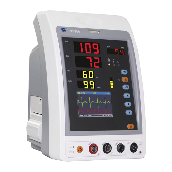
Built-in printer is optional to print out waveforms, and text information. 1.2 Product Name and Model Name: Vital Signs Monitor Model: PC-900 1.3 Intended Use This Monitor is a multi-functional instrument designed for monitoring the vital physiological signs of adult and pediatric patients. With the functions of real-time recording and displaying parameters, such as ECG, heart rate, non-invasive blood pressure, functional oxygen saturation, body temperature, and so on, it allows comprehensive analysis of patient’s physiological conditions. -
Page 10: Symbols On The Monitor
1.4 Symbols on the Monitor Adult Patient Waveform Freeze Pediatric Patient Pulse sync indicator (Reserved) Reserved Setup Menu NIBP Start/Cancel AC Power Alarm Silence DC Power Print Type BF applied part Type CF applied part with defibrillator protection Warning, refer to User Manual. Down Equal potential terminal ECG Lead Selection... -
Page 11: Chapter 2 Operating Principle
The overall structure of the monitor is shown in Fig. 2.1. Figure 2.1 PC-900 Vital Signs Monitor is module designed product; it consists of TEMP module, NIBP module, module, main control unit, printer module, display panel, and power supply block etc. -
Page 12: Chapter 3 Installation And Connection
Chapter 3 Installation and Connection 3.1 Appearance 3.1.1 Front Panel Figure 3.1 Front panel illustration Description: Alarm indicator Indicator Alarm Level Alarm Event Red flashing High priority alarm Exceeding the limits, low battery voltage Orange Medium priority alarm Leads or probe off Green light Normal... - Page 13 SYS: display systolic pressure value DIA: display diastolic pressure value. MAP: Display mean arterial pressure or measuring time of the latest group of NIBP measurement; they will be displayed alternately. The format of NIBP measuring time is “hh:mm”. If the tourniquet is in use, the cuff pressure will be displayed here. Note: two formats to display NIBP value: “×××mmHg”...
-
Page 14: Side Panel
Up: shift cursor forward/upward OK: to confirm selection or modification Down: shift cursor backward/downward Display: shift LCD display modes Waveform Freeze: freeze the current displayed waveform. ECG Lead Selection (Reserved function) : AC Power indicator : DC Power indicator AC Power DC Power indicator Descriptions indicator... -
Page 15: Rear Panel
3.1.3 Rear Panel Figure 3.2 Rear Panel Introduction to the rear panel: 1 Handle Nameplate CE mark Serial number Date of manufacture Authorised representative in the European community Manufacturer (including address and date) Disposal of this device according to WEEE regulations “FUSE T3.15 A”: Fuse holder. -
Page 16: Installation
3.2 Installation 3.2.1 Opening the Package and Check 1. Open the package, take out the monitor accessories from the box carefully and place it in a safe stable and easy to watch position. 2. Open the accompanying document to sort the accessories according to the packing list. Inspect the monitor for any mechanical damages Check all the accessories for any scratch or deformity, especially on connector, wire and probe parts... -
Page 17: Sensor Placement And Connection
If the battery is applied please recharge it after using the monitor to ensure sufficient power storage. It will take minimal 8 hours to charge battery from depletion to 90% charge. Do not use the device to monitor the patient if there are indications of damage or reminders of error. - Page 18 Figure 3.3 Cuff Placement Safety Instructions for NIBP Monitoring When taking the measurement of an infant’s (less than 10 years old) blood pressure, do NOT operate in the adult mode. The high inflation pressure may cause lesion or even body putrescence. It is recommended to take the blood pressure measurement manually.
-
Page 19: Spo 2 Sensor Connection
protection against electric shocks, and is defibrillator proof. 3.3.2 SpO Sensor Connection sensor is a very delicate part. Please follow the steps and procedures in operating it. Failure to operate it correctly can cause damage to the SpO sensor. Operation procedure: 1. -
Page 20: Temp Transducer Connection
use sensors, use a new sensor for each patient. Do not sterilize any sensor by irradiation, steam, or ethylene oxide. Safety Introductions for SpO Monitoring Continuous use of SpO sensor may result in discomfort or pain, especially for those with microcirculatory problem. It is recommended that the sensor should NOT be applied to the same place for over two hours, change the measuring site periodically if necessary. -
Page 21: Battery Installation
7. Put the shield back in position and secure it. Operation procedures for taking out printing paper roll: 1~2 steps are the same with the 1~2 steps mentioned above for loading printing paper. 3. Roll the loading roller anti-clockwise and pull the paper out. 4~5 steps are the same with the 6~7 steps mentioned above for loading printing paper. - Page 22 Please take out the battery before transport or storage. -14-...
-
Page 23: Chapter 4 Operations
Chapter 4 Operations 4.1 Initial Monitoring Screen If the ECG cable is disconnected from the monitor or leads off from the patient, the ECG waveform will become a base line in main display area and “Lead off” will appear at the left side of prompt info area (as shown in Figure 4.1). -
Page 24: Operation Instructions
This segment will display the ECG leads status, probe status, alarm silence counting-down timer, automatic NIBP measurement counting-down timer, over limit warning and other error messages for technical warning. If more than one event occurs or more status appears, the indication message will be displayed alternately at this segment. “NIBP C-D: XXX”: the counting-down timer of NIBP measurement is XXX seconds. -
Page 25: S P O Monitoring Screen
4.2 SpO Monitoring Screen Short time press “ Display” key to shift the screen view to SpO monitoring screen, as shown in Figure 4.2. Figure 4.2 SpO Monitoring Screen 4.2.1 Screen Description Title area: “PI: 3‰”: the perfusion index is 3‰; it displays only when “Setup Menu SpO Display”... -
Page 26: Operation Instructions
4.2.2 Operation Instructions “ ” key: freeze Plethysmogram on the screen. “ ” key: press this key to shift to next display view (SpO trend graph). “ ” key: Press it to print a trace of SpO plethysmogram, press it again to stop printing. -
Page 27: Operation Instructions
4.3.2 Operation Instructions Press “ ” key or “ ” key to highlight “trend length” or “cursor on” selection. 2. Press “ ” key to confirm. Press “ ” key or “ ” key again to select value of trend length (12/24/96 hours) if the selecting box stays in “trend length”... -
Page 28: Operation Instructions
value, and the fourth column is pulse rate (measured by NIBP module). “SYS/DIA/MAP” indicates the value of “systolic pressure/diastolic pressure/mean arterial pressure”. 4.4.1 Operation Instructions On NIBP List screen, if NIBP measurement is more than 6 groups, press “ ” key or “ ” key to scroll up or down through all the measurement values. -
Page 29: Ecg And Temperature Setup
related to its parameter monitoring will be disabled as well. 4.5.1 ECG and Temperature Setup Figure 4.7 ECG/TEMP Setup Screen Note: ECG monitoring function is optional. All the displays or setup related to ECG are reserved for future use. Screen Description: “TEMP ”: temperature alarm switch;... -
Page 30: Nibp Setup
“SpO Lo”: low limit of SpO alarm; range: “0~99”. “PR ”: pulse rate alarm switch; “ ” indicates PR alarm is on; “ ” indicates PR alarm is off. “PR Hi”: high limit of PR alarm; range: “22~250”. “PR Lo”: low limit of SpO alarm;... - Page 31 “Mode”: NIBP measuring mode, “manual”, “AUTO 1”, “AUTO 2”, …“AUTO 240” and “STAT” etc. options. “AUTO 1” means NIBP measurement takes once every one minute automatically; “AUTO 60” means NIBP measurement takes once every 60 minutes automatically; In AUTO mode, the counting-down timer is displayed in the “Prompt Info” area, as shown in Figure 4.1.
-
Page 32: Nurse Call
4.5.4 Nurse Call Figure 4.10 Nurse Call Setup Screen Screen Description: “Output level”: two options “low” or “high” output levels are available. When the calling system in hospital works in “Normal Open” mode, “low level” should be selected. When the calling system in hospital works in “Normal Close” mode, “high level” should be selected “Source”: three kinds of alarm sources can trig the nurse call: high level alarm, medium level alarm and low level alarm (multi-optional). -
Page 33: System Setup
4.5.5 System Setup Figure 4.11 System Setup Screen Screen Description: “Vol”: set beeper volume, “0~7” level adjustable, the set “0” i.e. no sound. The Alarm silence key “ ” will be disabled and the alarm silence indicator will be on to indicate no sound when the system volume is set as “0”. -
Page 34: Patient Info
4.5.6 Patient Info Figure 4.12 Patient Info Screen Screen Description: “ID”: change or set current patient’s ID number, 0~100 adjustable; “category”: change or set the category of current patient; two options “adult” and “pediatric”, the default is “adult”. Note: If the patient ID is changed, all the history data will be cleared, that means SpO trend graph and NIBP list will become empty. -
Page 35: Power Saving Mode
4.6 Power Saving Mode On the initial display screen, you can make the monitor stay in power saving mode for power saving. Short time press power button to shift screen to “Power Saving Mode” display screen, as shown in Figure 4.14. Figure 4.14 Power Saving Mode Press “... -
Page 36: Chapter 5 Alarm
Chapter 5 Alarm 5.1 Alarm Priority High Priority: TOUR C-D XXX seconds PR Over limit over limit SYS over limit DIA Over limit MAP Over limit NIBP error 1# NIBP error 2# NIBP error 3# NIBP error 4# NIBP error 5# Air leak Cuff error NIBP over range... -
Page 37: Alarm Silence
Audible Alarm Indications The audible alarm has different tone pitch and on-off beep patterns for each priority category. These are summarized in the Table below. Alarm Category Tone Pitch Beep Rate High priority alarm ~500Hz 2 beeps per 7 sec. Medium priority alarm ~700Hz 4 beeps per 9 sec. - Page 38 settings menu and adjust alarm limits or change alarm setting, then pay a close attention to the alarm. If the alarm is sent out according to your setting, it means the alarm function is effective. -30-...
-
Page 39: Chapter 6 Technical Specifications
Chapter 6 Technical Specifications 6.1 NIBP Monitoring 1. Measuring method: Oscillometric Technique 2. Pneumatic pressure measuring range: 0 mmHg~300mmHg 3. Accuracy of pressure measurement: ±3 mmHg 4. Cuff inflation time: <10 seconds (typical adult cuff) 5. Measurement time on the average: < 90 seconds 6. -
Page 40: Temp Monitoring
6.4 TEMP Monitoring 1. TEMP measuring range: 25.0 ~45.0 2. TEMP measuring accuracy: ±0.2 3. TEMP responding time: ≤150s 6.5 Data Recording 1. Sensitivity selection tolerance: ±5% 2. Recording speed: 25mm/s 3. Recording speed accuracy: ±10% 4. Hysteresis: ≤0.5mm 5. Frequency response: Monitoring mode: 0.5~40Hz 6. -
Page 41: Manufacturer S Declaration
EQUIPMENT AND SYSTEMS Guidance and manufacturer’s declaration-electromagnetic emission PC-900/Classic-90 Vital Signs Monitor is intended for use in the electromagnetic environment specified below. The customer or the user of the equipment or system should assure that it is used in such an environment. - Page 42 EQUIPMENT AND SYSTEMS Guidance and manufacturer’s declaration-electromagnetic emission PC-900/Classic-90 Vital Signs Monitor is intended for use in the electromagnetic environment specified below. The customer or the user of the equipment or system should assure that it is used in such an environment.
- Page 43 Guidance and manufacturer’s declaration – electromagnetic immunity PC-900/Classic-90 Vital Signs Monitor is intended for use in the electromagnetic environment specified below. The customer or the user of PC-900/Classic-90 Vital Signs Monitor should assure that it is used in such an electromagnetic environment.
- Page 44 RF transmitters, and electromagnetic site survey should be considered. If the measured field strength in the location in which PC-900/Classic-90 Vital Signs Monitor is used exceeds the applicable RF compliance level above, PC-900/Classic-90 Vital Signs Monitor should be observed to verify normal operation.
-
Page 45: Chapter 7 Packaging And Accessories
For transmitters rated at a maximum output power not listed above, the recommended separation distance d in metres (m) can be determined using the equation applicable to the frequency of the transmitter, where p is the maximum output power rating of the transmitter in watts (W) according to the transmitter manufacturer. - Page 46 -38-...
-
Page 47: Chapter 8 Working Principle
Chapter 8 Working Principle 8.1 NIBP Monitoring 8.1.1 Measuring Principle Blood pressure may be measured in an invasive way (whereby the sensor will be inserted into blood vessel directly) or a non-invasive way. The non-invasive way includes several methodologies, such as the Korotkoff Sound Method and oscillating method. The Korotkoff Sound Method is used as a conventional way, whereby stethoscope is used to measure the blood pressure. -
Page 48: Factors Affecting Nibp Measuring
The Oscillating method vs. the Korotkoff Sound Method Blood pressure measurement by the oscillating method and Korotkoff Sound Method has good correlation with the invasive measurement. Notwithstanding, any of the non-invasive blood pressure measurements has its one-sidedness when it is compared to the invasive measurement. The oscillating method has its advantages over the Korotkoff Sound Method in less error, higher reliability and stability. -
Page 49: Clinical Limitations
sweater ) to take measurement; The testee shall lie in bed or sit in chair, make the cuff and heart at the same level, the result will be most accurate, other postures may have inaccurate result; During measuring, do not move your arm or the cuff; The measuring interval shall longer than 2 minutes, in continuous measurement, too short interval may cause arm extrusion, blood quantity increases, then cause blood pressure increases. -
Page 50: Spo 2 Monitoring
8.2 SpO Monitoring 8.2.1 Measuring Principle Based on Lamber-Beer law, the light absorbance of a given substance is directly proportional with its density or concentration. When the light with certain wavelength emits on human tissue, the measured intensity of light after absorption, reflecting and attenuation in tissue can reflect the structure character of the tissue by which the light passes. -
Page 51: Clinical Limitations
8.2.4 Clinical Limitations As the measure is taken on the basis of arteriole pulse, substantial pulsating blood stream of subject is required. For a subject with weak pulse due to shock, low ambient/body temperature, major bleeding, or use of vascular contracting drug, the SpO waveform (PLETH) will decrease. - Page 52 manufacturer which calibration curve is used, if necessary, request the manufacturer for its dedicated calibration curve and download it into the tester. -44-...
-
Page 53: Chapter 9 Troubleshooting
Chapter 9 Troubleshooting 9.1 No Display on the Screen Shut down the machine and unplug the power. Use a universal meter to check if the outlet has proper voltage, if the power cable is in good condition, and if the power cable is properly connected with this apparatus or outlet. -
Page 54: Chapter 10 Maintenance
Chapter 10 Maintenance 10.1 Service and Examination 10.1.1 Daily Examination Before using the monitor, the checks below should be carried out: Check the monitor for any mechanical damage; Inspect the exposed parts and the inserted parts of all the leads, and the accessories; Examine all the functions of the monitor that are likely to be used for patient monitoring, and ensure that it is in good working condition;... -
Page 55: Service
After battery ageing phenomenon occurring, to avoid explosion risk do NOT throw the battery into fire. Do not hit or strike it with force; Do not use this battery on other devices; Do not use this battery below -10 or above 40 ; Dispose of the battery, the local law should be followed. -
Page 56: Cleaning, Sterilization And Disinfection Of Accessories
Do not put any parts of the monitor or its accessories in the liquid. If the monitor is accidentally wetted it should be thoroughly dried before use. The rear cover can be removed by qualified service technician to verify absence of water. -
Page 57: Chapter 11 Appendix
Chapter 11 Appendix 11.1 Prompt information explanations Mute C-D: XXX seconds Alarm silence count down: XXX seconds NIBP C-D: XXX seconds NIBP auto measuring cycle count down: XXX seconds TOUR C-D: XXX Tourniquet alert count down: XXX seconds Probe off probe fells off PR over limit PR value exceeds the high/low alarm limit... -
Page 58: Default Alarming Values And Setup Range
11.2 Default Alarming Values and Setup Range Default Mode Alarm range Adult Pediatric Parameter 32~250 High 180mmHg 130mmHg 30~248 60mmHg 50mmHg 22~232 High 120mmHg 90mmHg 20~230 50mmHg 40mmHg 28~242 High 160mmHg 110mmHg 26~240 50mmHg 40mmHg High 1%~100% 100% 100% 0%~99% High (22~250) bpm 180bpm... -
Page 59: Instructions For Spo Probe
11.4 Instructions for SpO Probe Instructions for Pediatric SpO Finger Clip Sensor Intended Use When used with a compatible patient monitor or a pulse oximeter device, the sensor is intended to be used for continuous, non-invasive functional arterial oxygen saturation (SpO2) and pulse rate monitoring for pediatric patients weighing between 10~40kg. - Page 60 Do not apply tape to secure the sensor in place or to tape it shut; venous pulsation may lead to inaccurate saturation measurements. Do not immerse sensor as it causes short. Do not use NIBP or other constructing instruments on same appendage as sensor for blood flow interrupted by NIBP cuff or circulatory patient condition will result in no pulse found or loss of pulse.
- Page 61 Caution: Do not sterilize by irradiation steam, or ethylene oxide. Warnings This sensor is for use only with compatible patient monitors or pulse oximeter devices. Use of this sensor with instruments other than compatibles may result in improper performance. Some factors may affect the accuracy of saturation measurements. Such factors include: excessive patient motion, fingernail polish, use of intravascular dyes, excessive light, poorly perfused finger, extreme finger sizes or improper placement of the sensor.
- Page 62 the top of the hand (C). Plug the sensor into the oximeter and verify proper operation as described in the oximeter operator’s manual. Inspect the monitoring site every 4 hours for skin integrity. Before each use, surface-clean sensor and cable with a soft gauze pad by saturating it with a solution such as 70% isopropyl alcohol.
- Page 63 The warranty is valid for 12 months from the date of supply of GIMA. During the period of validity of the warranty, GIMA will repair and/or replace free of charge all the defected parts due to production reasons. Labor costs and personnel traveling expenses and packaging not included.
Need help?
Do you have a question about the PC-900 and is the answer not in the manual?
Questions and answers