
Related Manuals for Gima PC-900


Summary of Contents for Gima PC-900
- Page 1 PROFESSIONAL MEDICAL PRODUCTS VITAL SIGNS MONITOR PC-900 35120 0476 Gima S.p.A. Via Marconi, 1 - 20060 Gessate (MI) Italy gima@gimaitaly.com - export@gimaitaly.com www.gimaitaly.com Made in China...
- Page 2 This Manual is written and compiled in accordance with the IEC 60601-1 ( Medical electrical equipment Part1: General requirements for safety)and MDD 93/42/EEC. It complies with both international and enterprise standards and is also approved by State Technological Supervision Bureau. The Manual is written for the current PC-900 Vital Signs Monitor.
- Page 3 User Manual for Vital Signs Monitor Instructions to User Dear Users, Thank you very much for purchasing our product. Please read the following information very carefully before using this device. Read these instructions carefully before using this monitor. These instructions describe the operating procedures to be followed strictly.
- Page 4 User Manual for Vital Signs Monitor the blood pressure measurement. DO NOT take blood pressure measurement from a limb receiving ongoing transfusion or intubations or skin lesion area, otherwise, damages may be caused to the limb. Continuous use of SpO sensor may result in discomfort or pain, especially for those with microcirculatory problem.
-
Page 5: Table Of Contents
User Manual for Vital Signs Monitor Table of Contents CHAPTER 1 OVERVIEW..................1 1.1 F ..........................1 EATURES 1.2 P ....................1 RODUCT AME AND ODEL 1.3 I ......................... 1 NTENDED 1.4 S ............................ 1 AFETY 1.5 S ....................2 YMBOLS ON THE ONITOR CHAPTER 2 OPERATING PRINCIPLE..............3 2.1 O... - Page 6 User Manual for Vital Signs Monitor 4.3.2 Operation Instructions......................... 23 4.4 NIBP L ........................24 CREEN 4.4.1 Operation Instructions......................... 24 4.5 S .........................25 CREEN 4.5.1 Operation Instructions......................... 25 4.6 ECG R ......................25 ECALL CREEN 4.6.1 Operation Instructions......................... 26 4.7 S ......................
- Page 7 User Manual for Vital Signs Monitor 7.1 P ........................... 41 ACKAGING 7.2 A ......................... 41 CCESSORIES CHAPTER 8 MONITORING PARAMETER............. 42 8.1 ECG M .........................42 ONITORING 8.1.1 How to Obtain High Quality ECG and Accurate Heart Rate Value............ 42 8.1.2 Factors affecting ECG signal......................43 8.2 NIBP M ........................43 ONITORING...
- Page 8 User Manual for Vital Signs Monitor 11.1 P ................52 ROMPT INFORMATION EXPLANATIONS 11.2 D .............. 53 EFAULT LARMING ALUES AND ETUP ANGE 11.3 A ..................54 BBREVIATION OF ARRHYTHMIA 11.4 A .......................55 CCESSORIES 11.5 I ..................56 NSTRUCTIONS FOR ROBE 11.6 EMC ............................61...
-
Page 9: Chapter 1 Overview
Built-in printer is optional to print out waveforms, and text information. 1.2 Product Name and Model Name: Vital Signs Monitor Model: PC-900 1.3 Intended Use This Monitor is a multi-functional instrument designed for monitoring the vital physiological signs of adult and pediatric patients. -
Page 10: Symbols On The Monitor
User Manual for Vital Signs Monitor 1.5 Symbols on the Monitor Adult Patient Waveform Freeze Pediatric Patient Pulse sync indicator Neonatal Patient Setup Menu ~ NIBP Start/Cancel AC Power Alarm Silence DC Power Print Type BF applied part Type applied part with ▲... -
Page 11: Chapter 2 Operating Principle
The overall structure of the monitor is shown in Fig. 2.1. Figure 2.1 2.2 Conformation PC-900 Vital Signs Monitor is module designed product; it consists of ECG/TEMP module (optional), NIBP module (optional), SpO module (optional), main control unit, printer module (optional), display panel, and power supply block etc. -
Page 12: Chapter 3 Installation And Connection
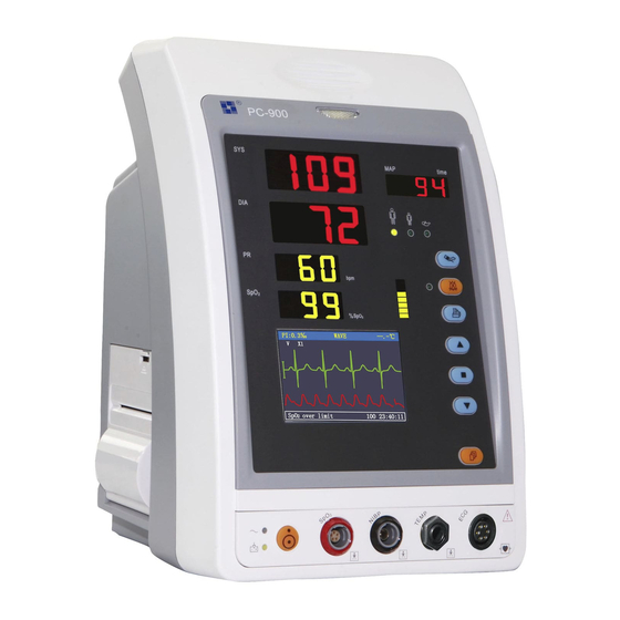
User Manual for Vital Signs Monitor Chapter 3 Installation and Connection 3.1 Appearance 3.1.1 Front Panel Figure 3.1 Front panel illustration Description: Alarm indicator Indicator Alarm Level Alarm Event Red flashing High priority alarm Exceeding the limits, low battery voltage Orange flashing Medium priority alarm Leads or probe off... - Page 13 User Manual for Vital Signs Monitor SYS: display systolic pressure value. DIA: display diastolic pressure value. MAP: When NIBP measurement mode is set to “manual” and “STAT”: Display mean arterial pressure or measuring time of the latest group of NIBP measurement; they will be displayed alternately.
-
Page 14: Side Panel
User Manual for Vital Signs Monitor 15 Alarm silence indicator: When it is on, it indicates that the monitor stays in alarm silence status. Print: the internal printer is optional, press this key to print the current measuring data; Up: shift cursor forward/upward 18 ▇... -
Page 15: Rear Panel
User Manual for Vital Signs Monitor 3.1.3 Rear Panel Figure 3.2 Rear Panel Introduction to the rear panel: 1 Handle 2 Fan 3 Nameplate CE mark Serial number Date of manufacture Authorised representative in the European community Manufacturer (including address and date) Disposal of this device according to WEEE regulations 4 “FUSE T3.15 A”: Fuse holder. -
Page 16: Installation
User Manual for Vital Signs Monitor 3.2 Installation 3.2.1 Opening the Package and Check 1. Open the package, take out the monitor accessories from the box carefully and place it in a safe stable and easy to watch position. 2. Open the accompanying document to sort the accessories according to the packing list. Inspect the monitor for any mechanical damages Check all the accessories for any scratch or deformity, especially on connector, wire and probe parts... -
Page 17: Sensor Placement And Connection
User Manual for Vital Signs Monitor Do not use the device to monitor the patient if there are indications of damage or reminders of error. Please contact the local dealer or our company. It’s recommended to delay 1 minute to start it again. 3.3 Sensor Placement and Connection 3.3.1 ECG Cable Connection ECG measurement is to collect the ECG signal via the ECG electrodes. - Page 18 Do not attach electrodes on the patient with an inflammation of the skin or scores on skin. PC-900 Vital Signs Monitor can only be equipped with ECG leads provided by our company; using ECG leads supplied by other companies may cause improper performance or poor protection while using defibrillator.
-
Page 19: Blood Pressure Cuff Connection
User Manual for Vital Signs Monitor PC-900 Vital Signs Monitor can resist against defibrillator and electrosurgical unit. Readings may be inaccurate for a short time after or during using defibrillator or electrosurgical unit. Transient caused by cable circuitry blocks while monitoring may be similar to the real heartbeat waveform, as a result resistance heart rate alarm rings. - Page 20 User Manual for Vital Signs Monitor Pressure Accuracy Verification Pressure Accuracy Verification is a function to inspect the accuracy of pressure measurement by the NIBP module inside the device. Technician or equipment manager should do pressure accuracy verification every half year or year in order to check if the pressure measurement still conforms to the requirement of product performance.
- Page 21 User Manual for Vital Signs Monitor Adult 300mmHg Child 240mmHg Neonate 140mmHg Table B After the verification, do press the button again to return to normal working mode, then continue other operation, or the NIBP key will be invalid. Pressure accuracy verification must be operated by technician or equipment manager. Doctor or nurse is not allowed to do the verification, it is very dangerous especially when the pressure cuff is still on patients.
-
Page 22: Spo Sensor Connection
User Manual for Vital Signs Monitor The measures should be taken at appropriate intervals. Continuous measurement at too short intervals may lead to pressed arm, reduced blood flow and lower blood pressure, and resulting inaccurate measure of blood pressure. It is recommended to take measurement at intervals of more than two minutes. - Page 23 User Manual for Vital Signs Monitor 3. If the neonate SpO sensor is used, please follow Figure 3.7 to connect. Sensor adapter: wrapper Y type sensor Figure 3.7 Neonate SpO sensor placement High ambient light sources such as surgical lights (especially those with a xenon light source), bilirubin lamps, fluorescent lights, infrared heating lamps, and direct sunlight can interfere with the performance of an sensor.
-
Page 24: Temp Transducer Connection
User Manual for Vital Signs Monitor 3.3.4 TEMP Transducer Connection Connecting methods: 1. Attach the transducers to the patient firmly; 2. Connect the cable to TEMP probe connector in the front panel. Note: When unplugging the probe, be sure to hold the head of the connector and pull it out. 3.3.5 Loading printing paper Operation procedures for loading printing paper: 1. - Page 25 User Manual for Vital Signs Monitor Power Indicator Open button Error Indicator Paper cartridge Figure 3.9 P8 printer Loading printing paper: Step 1: press and hold down the cartridge button to open the paper cartridge; Step 2: Install the paper to the printer properly, pull the paper out of the printer for 2 cm, as shown in figure 3.10.
-
Page 26: Battery Installation
User Manual for Vital Signs Monitor 3.3.6 Battery Installation 1. Ensure that the monitor is not connected to AC power supply and the monitor is turned off. 2. Open the battery cover and place the battery in the direction as shown in Fig. 3.11 to insert the battery into any one of battery compartments. -
Page 27: Chapter 4 Operations
User Manual for Vital Signs Monitor Chapter 4 Operations 4.1 Initial Monitoring Screen When the parameter configuration of monitor is “ECG+SpO +NIBP”, once powered up, the LCD will display the initial monitoring screen, this is the default display screen as well. When the parameter configuration of monitor is “SpO +NIBP”, the screen will not display ECG waveform and data, but the operation is similar. -
Page 28: Operation Instructions
User Manual for Vital Signs Monitor “PI: 3‰”: the perfusion index is 3‰; it displays only when “Setup Menu→SpO →PI Display” is set as “ON”. Note: PI display function is optional and it needs hardware support. Main display area: When ECG leads is attached on the patient and connected to the monitor well, ECG waveform will be displayed in the main display area. - Page 29 User Manual for Vital Signs Monitor “ ” key: short press this key (about 1 second) to turn on or turn off the alarm sound temporarily; Long time press it to enter into the alarm setup shortcut menu as shown in figure 4.3. If not turn off “ECG Lead off”...
-
Page 30: Ecg Monitoring Screen
User Manual for Vital Signs Monitor 4.2 ECG Monitoring Screen Short pressing “ Display” key to shift the screen view to ECG monitoring screen, as shown in Figure 4.4. Figure 4.4 ECG Monitoring Screen Note: if you need to store the measuring data, please set the option of “store” as “on” on ECG TEMP setting screen. -
Page 31: Trend Graph Display
User Manual for Vital Signs Monitor 4.3 Trend Graph Display Short pressing “ Display” key to shift the screen view to trend graph display screen, as shown in Figure 4.5. Trend graph Trend length Figure 4.5 Trend Graph 4.3.1 Screen Description “12 hours”: the trend length of trend graph;... -
Page 32: Nibp List Screen
User Manual for Vital Signs Monitor step is, as long as you press “▲” or “▼” key towards the other direction, the step becomes 1 and towards the other direction. 4. Press: “ ” key: press this key to shift to next display view. “... -
Page 33: Spo 2 List Screen
User Manual for Vital Signs Monitor 4.5 SpO List Screen Short pressing “ Display” key to shift the screen to SpO List screen, as shown in Figure 4.7 Figure 4.7 SpO List The first column is the date, the second column is SpO measuring time, the third column is SpO value, and the fourth column is pulse rate. -
Page 34: Operation Instructions
User Manual for Vital Signs Monitor 4.6.1 Operation Instructions ■ 1. Press “ ” key to confirm “view”. ▲ ▼ ■ 2. Then press “ ” key or “ ” key to shift yellow selecting box to choose a record. After pressing “ ”... -
Page 35: Ecg And Temperature Setup
User Manual for Vital Signs Monitor 4. Press “ ” to exist from Setup Menu Screen. ☞ At Setup Menu Screen or its submenu screen, when pressing “ ” key, the default display screen will be printed. The following will cover each functional parameter’s setting up. Note: If you disable Hi and Lo limit alarm function of parameter monitoring, all the alarms related to its parameter monitoring will be disabled as well. -
Page 36: Spo 2 Setup
User Manual for Vital Signs Monitor “Store”: decide whether to store ECG data or not. If your selection is “off”, thereafter the ECG data measured will not be stored. “T probe”: the type of temperature probe “KRK”. 4.7.2 SpO Setup Figure 4.12 SpO Setup Screen Screen Description:... -
Page 37: Nibp Setup
User Manual for Vital Signs Monitor 4.7.3 NIBP Setup Figure 4.13A NIBP Setup Figure 4.13B Tourniquet Setup Figure 4.13C Adjust Setup NIBP Setup Screen Description: “SYS ”: systolic pressure alarm switch; “ ” indicates systolic pressure alarm is on; “ ”... - Page 38 User Manual for Vital Signs Monitor the counting-down timer is displayed in the “Prompt Info” area. “Initial pressure setup”: Cuff pre-inflation pressure value is default for neonates: pre-inflation range: 60~80mmHg, default value: “70” mmHg; for infants: pre-inflation range: 80~140 mmHg, default value: “100” mmHg; for adults: pre-inflation range: 80~200mmHg, default value: “150”...
- Page 39 User Manual for Vital Signs Monitor calibration the “Stop” shifts to “Start”) NIBP Cali Mode 2:Receiving the exterior pressure. The exterior pressure source pressurize to the module to proceed the pressure calibration. Move the cursor to NIBP calibration mode 2”Start” button, click the OK button to begin the NIBP calibration.(Meanwhile, the “Start”...
-
Page 40: Nurse Call
User Manual for Vital Signs Monitor 4.7.4 Nurse Call Figure 4.14 Nurse Call Setup Screen Screen Description: “Output level”: two options “low” or “high” output levels are available. When the calling system in hospital works in “Normal Open” mode, “low level” should be selected. When the calling system in hospital works in “Normal Close”... -
Page 41: Patient Info
User Manual for Vital Signs Monitor Screen Description: “Volume”: set beeper volume, “1~7” level adjustable, the factory default is 03. It is recommended that the alarm volume shouldn’t be adjusted lower than the factory default value unless the nursing personnel keeps close attention and surveillance on the patients and the device at all times. “key beep”: to turn on/off key beep;... -
Page 42: Date/Time
User Manual for Vital Signs Monitor 4.7.7 Date/Time Figure 4.17 Data/Time Setup Screen Screen Description: “yy 07 mm 09 dd 21”: date setting, “07-09-21” shows the date is September 21 , 2007. “hh 10 mm 15 ss 20”: time setting, “09:20:21” shows the time is10:15:20. 4.7.8 Recover Default Settings ▲... -
Page 43: Chapter 5 Alarm
User Manual for Vital Signs Monitor Chapter 5 Alarm 5.1 Alarm Priority High Priority: TOUR C-D:XXX seconds PR Over limit over limit SYS over limit DIA Over limit MAP Over limit NIBP error 1# NIBP error 2# NIBP error 3# NIBP error 4# NIBP error 5# Air leak... -
Page 44: Alarm Silence
User Manual for Vital Signs Monitor Audible Alarm Indications The audible alarm has different tone pitch and on-off beep patterns for each priority category. These are summarized in the Table below. Alarm Category Tone Pitch Beep Chain High priority alarm ~400Hz 10 beeps pause 3 sec. -
Page 45: Chapter 6 Technical Specifications
User Manual for Vital Signs Monitor Chapter 6 Technical Specifications 6.1 ECG Monitoring 1. Input signals range in amplitude: ± (0.5 mVp ~ 5 mVp) 2. Heart rate display range: 15 bpm ~ 350 bpm 3. Heart rate display accuracy: ± 1% or ± 2 bpm, whichever is greater. 4. -
Page 46: Temp Monitoring
User Manual for Vital Signs Monitor Additional declarations to conform the particular standard of IEC 60601-2-27 “Medical electrical equipment – Part 2-27: Particular requirements for the safety, including essential performance, of electrocardiographic monitoring equipment” Direct current for Applied current less than 0.1 microamperes. respiration, leads-off sensing, and active noise suppression... -
Page 47: Spo 2 Monitoring
User Manual for Vital Signs Monitor 6.4 SpO Monitoring 1. Transducer: dual-wavelength LED Wavelength: Red light: 663 nm, Infrared light: 890 nm. Maximal optical output power: less than 2mW maximum average 2. SpO measuring range: 35%~100% 3. SpO measuring accuracy: Arms is not greater than 3% for SpO range from 70% to 100% *NOTE: Arms is accuracy defined as root-mean-square value of deviation according to ISO 9919 4. -
Page 48: Classification
User Manual for Vital Signs Monitor Relative humidity: 10 ~ 95% Atmospheric pressure: 50.0kPa ~107.4kPa 6.9 Classification Safety standard IEC 60601-1 The type of protection against electric shock ClassⅠequipment. The degree of protection against electric shock Type BF, CF applied parts Electro-Magnetic Compatibility: Group I, Class A... -
Page 49: Chapter 7 Packaging And Accessories
User Manual for Vital Signs Monitor Chapter 7 Packaging and Accessories 7.1 Packaging The product is packed in high quality corrugated cartons with foam inside to protect the equipment against damage in the shipping and handling process. Weight: Details see the indication on the outer package. Dimension: 360(L)×320(W)×410(H) (mm) 7.2 Accessorie Adult SpO2 probe -- 15044074... -
Page 50: Chapter 8 Monitoring Parameter
User Manual for Vital Signs Monitor Chapter 8 Monitoring Parameter 8.1 ECG Monitoring 8.1.1 How to Obtain High Quality ECG and Accurate Heart Rate Value The electrocardiogram (ECG or EKG) is primarily a tool for evaluating the electrical events within the heart. The action potentials of cardiac-muscle cells can be viewed as batteries that cause charge to move throughout the body fluids. -
Page 51: Factors Affecting Ecg Signal
User Manual for Vital Signs Monitor 8.1.2 Factors affecting ECG signal Interference from Electrosurgical Unit; Doesn’t filter the interference waveform; Poor grounding; Electrodes are not placed properly; Use expired electrode or use disposable electrode repeatedly; The skin placed electrode is unclean or poor contract caused by scurf and hair; Electrode long-time used. -
Page 52: Factors Affecting Nibp Measuring
User Manual for Vital Signs Monitor those taken by Korotkoff Sound Method? Why the measures are inclined to decline? Why, in some cases, no result is obtained in spite of the inflation actions? Why the measure values have big discreteness and even abnormal data in some cases? Why the SpO waveforms may disappear suddenly? ...and so on. -
Page 53: Clinical Limitations
User Manual for Vital Signs Monitor During measuring, do not move your arm or the cuff; The measuring interval shall longer than 2 minutes, in continuous measurement, too short interval may cause arm extrusion, blood quantity increases, then cause blood pressure increases. Keep the patient still and stop talking before and during measuring;... -
Page 54: Spo Measurement Restrictions (Interference Reason)
User Manual for Vital Signs Monitor 8.3.2 SpO Measurement Restrictions (interference reason) Intravascular dyes such as indocyanine green or methylene blue Exposure to excessive illumination, such as surgical lamps, bilirubin lamps, fluorescent lights, infrared heating lamps, or direct sunlight. Vascular dyes or external used color-up product such as nail enamel or color skin care Excessive patient movement Placement of a sensor on an extremity with a blood pressure cuff, arterial catheter, or intravascular line... -
Page 55: Points To Be Noted In Spo And Pulse Measuring
User Manual for Vital Signs Monitor 8.3.5 Points to be noted in SpO and Pulse Measuring The finger should be properly placed (see the attached illustration of this instruction manual), or else it may cause inaccurate measurement result. Make sure that capillary arterial vessel beneath the finger is penetrated through by red and infrared lights. -
Page 56: Chapter 9 Troubleshooting
User Manual for Vital Signs Monitor Chapter 9 Troubleshooting 9.1 No Display on the Screen Shut down the machine and unplug the power. Use a universal meter to check if the outlet has proper voltage, if the power cable is in good condition, and if the power cable is properly connected with this apparatus or outlet. -
Page 57: Chapter 10 Maintenance
User Manual for Vital Signs Monitor Chapter 10 Maintenance 10.1 Service and Examination 10.1.1 Daily Examination Before using the monitor, the checks below should be carried out: Check the monitor for any mechanical damage; Inspect the exposed parts and the inserted parts of all the leads, and the accessories; Examine all the functions of the monitor that are likely to be used for patient monitoring, and ensure that it is in good working condition;... -
Page 58: Service
User Manual for Vital Signs Monitor After battery ageing phenomenon occurring, to avoid explosion risk do NOT throw the battery into fire. Do not hit or strike it with force; Do not use this battery on other devices; Do not use this battery below -10℃ or above 40℃; Dispose of the battery, the local law should be followed. -
Page 59: Cleaning, Sterilization And Disinfection Of Accessories
User Manual for Vital Signs Monitor Clean the exterior of the connector only. Dilute the cleanser. Do not let any liquid flow into the shell or any parts of the monitor. Do not let the cleanser and disinfectant stay on its surface. Do not perform high pressure sterilization to the monitor. -
Page 60: Chapter 11 Appendix
User Manual for Vital Signs Monitor Chapter 11 Appendix 11.1 Prompt information explanations Mute C-D: XXX seconds Alarm silence count down: XXX seconds NIBP C-D: XXX seconds NIBP auto measuring cycle count down: XXX seconds TOUR C-D: XXX seconds Tourniquet alert count down: XXX seconds Probe off probe fells off PR over limit... -
Page 61: Default Alarming Values And Setup Range
User Manual for Vital Signs Monitor 11.2 Default Alarming Values and Setup Range The default alarming value: Mode Adult Pediatric Neonate Parameter High limit 180bpm 200bpm 220bpm Low limit 40bpm 50bpm 50bpm High limit 180mmHg 130mmHg 110mmHg Low limit 60mmHg 50mmHg 50mmHg High limit... -
Page 62: Abbreviation Of Arrhythmia
User Manual for Vital Signs Monitor 11.3 Abbreviation of arrhythmia Type Abbreviation Full name ECG TACHY Tachycardia ECG BRADY Bradycardia ECG ARREST Cardiac Arrest MISS BEAT Missing Beat VE EARLY Ventricular Premature Contraction (VPC) SVE EARLY Supra-ventricular Premature Contraction (SVPC) VE COUPLET Ventricular Couplet SVE COUPLET... -
Page 63: Accessories List
User Manual for Vital Signs Monitor 11.4 Accessories List Part No. Part Name Remark Standard 15010513 ECG cable Standard 5101-0101310 ECG electrode Standard 15044051 Adult SpO Finger clip sensor 15044061 Adult SpO Finger rubber sensor Optional 15044041 Pediatric SpO Finger clip sensor Optional 15044063 Neonate SpO... -
Page 64: Instructions For S P O 2 Probe
User Manual for Vital Signs Monitor 11.5 Instructions for SpO Probe Instructions for Neonate SpO Y-type Sensor Intended Use When used with a compatible patient monitor or a pulse oximeter device, this sensor is intended to be used for continuous, non-invasive functional arterial oxygen saturation (SpO ) and pulse rate monitoring for neonates (1-3 kg). - Page 65 User Manual for Vital Signs Monitor Instructions for Pediatric SpO Finger Clip Sensor Intended Use When used with a compatible patient monitor or a pulse oximeter device, the sensor is intended to be used for continuous, non-invasive functional arterial oxygen saturation (SpO2) and pulse rate monitoring for pediatric patients weighing between 10~40kg.
- Page 66 User Manual for Vital Signs Monitor Instructions for Adult SpO Finger Rubber Sensor Intended Use When used with a compatible patient monitor or a pulse oximeter device, this SpO sensor is intended to be used for continuous, non-invasive functional arterial oxygen saturation (SpO ) and pulse rate monitoring for patients weighing greater than 50kg.
- Page 67 User Manual for Vital Signs Monitor Intended Use When used with a compatible patient monitor or a pulse oximeter device, the sensor is intended to be used for continuous, non-invasive functional arterial oxygen saturation (SpO ) and pulse rate monitoring for patients weighing greater than 40kg.
- Page 68 User Manual for Vital Signs Monitor Creative offers a 6-month warranty against manufacturing defects for the SpO sensors mentioned above in its undamaged condition. If you have any question regarding any of SpO sensor instructions, please contact info@ creative-sz.com, or your local dealer.
-
Page 69: Emc
User Manual for Vital Signs Monitor 11.6 EMC Compliance Note: Warnings: ● The instrument conforms to the requirements of IEC60601- 1 - 2 , EN 60601-1-2 standards for electromagnetic compatibility. ● The user shall install and use the EMC information provided in the random file. ●... - Page 70 User Manual for Vital Signs Monitor IEC60601 test Compliance Electromagnetic Immunity test level level environment -guidance Floors should be wood, ± 8 kV contact concrete or ceramic tile. If Electrostatic ± 8 kV contact ± 2 kV, ± 4 kV, floors are covered with discharge(ESD) ±...
- Page 71 User Manual for Vital Signs Monitor Table 3 Guidance and manufacturer’s declaration – electromagnetic immunity The Vital Signs Monitor is intended for use in the electromagnetic environment specified below. The customer or the user of The Vital Signs Monitor should assure that it is used in such an electromagnetic environment.
- Page 72 User Manual for Vital Signs Monitor is affected by absorption and reflection from structures, objects and people. a: Field strengths from fixed transmitters, such as base stations for radio (cellular / cordless) telephones and land mobile radios, amateur radio, AM and FM radio broadcast and TV broadcast cannot be predicted theoretically with accuracy.
- Page 73 User Manual for Vital Signs Monitor a) For some services, only the uplink frequencies are included b) The carrier shall be modulated using a 50 % duty cycle square wave signal. c) As an alternative to FM modulation, 50 % pulse modulation at 18 Hz may be used because while it does not represent actual modulation, it would be worst case.
- Page 74 Disposal: The product must not be disposed of along with other domestic waste. The users must dispose of this equipment by bringing it to a specific recycling point for electric and electronic equipment. GIMA WARRANTY TERMS The Gima 12-month standard B2B warranty applies.
Need help?
Do you have a question about the PC-900 and is the answer not in the manual?
Questions and answers