Table of Contents
Advertisement
Quick Links
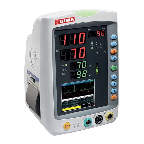
PROFESSIONAL MEDICAL PRODUCTS
GIMA VITAL SIGNS MONITORS
VITAL PRO-SNET
User manual
ATTENTION: The operators must
carefully read and completely understand
the present manual before using the product.
35124 / PC-900PRO(SNET)
Shenzhen Creative Industry Co., Ltd.
2/F Block 3 Nanyou Tian'an Industry Town
518054 Shenzhen, GD - P.R.C.
Made in China (P.R.C.)
Shanghai International Holding Corp. GmbH (Europe)
Eiffestrasse 80, 20537 Hamburg - Germany
Gima S.p.A.
Via Marconi, 1 - 20060 Gessate (MI) Italy
gima@gimaitaly.com - export@gimaitaly.com
www.gimaitaly.com
0123
Advertisement
Table of Contents

Related Manuals for Gima VITAL PRO-SNET PC-900PRO


Summary of Contents for Gima VITAL PRO-SNET PC-900PRO
- Page 1 Gima S.p.A. Via Marconi, 1 - 20060 Gessate (MI) Italy gima@gimaitaly.com - export@gimaitaly.com www.gimaitaly.com PROFESSIONAL MEDICAL PRODUCTS GIMA VITAL SIGNS MONITORS VITAL PRO-SNET User manual ATTENTION: The operators must carefully read and completely understand the present manual before using the product.
- Page 2 State Technological Supervision Bureau. The Manual is written for the current Gima Vital Signs Monitor. The Manual describes, in accordance with the Gima Vital Signs Monitor’s features and requirements, main structure, functions, specifications, correct methods for transportation, installation, usage, operation, repair, maintenance and storage, etc.
- Page 3 Each time the Gima Vital Signs Monitor is used, check the alarm limits to ensure that they are appropriate for the patient being monitored. The Gima Vital Signs Monitor is intended only as an adjunct in patient assessment. It must be used in con- junction with clinical signs and symptoms.
- Page 4 All the parts of the Gima Vital Signs Monitor should NOT be replaced at will. If necessary, please use the components provided by the manufacturer or those that are of the same model and standards as the ac- cessories along with the monitor which are provided by the same factory, otherwise, negative effects con- cerning safety and biocompatibility etc.
-
Page 5: Table Of Contents
Table of Contents Chapter 1 Overview ............................7 1.1 Features ..........................7 1.2 Product Name and Model ....................... 7 1.3 Intended Use .......................... 7 1.4 Safety ............................7 Chapter 2 Operating Principle ........................8 2.1 Overall Structure ........................8 2.2 Conformation .......................... 8 Chapter 3 Installation and Connection ....................... - Page 6 6.4 SpO 2 Monitoring........................42 6.5 Pulse Rate monitoring ......................43 6.6 Data Recording ........................43 6.7 Other Technical Specifications ..................... 43 6.8 Operating Environment ......................43 6.9 Classification......................... 43 6.10 Other Technical Information 6.10.1 Additional description for ECG monitoring .............. 43 6.10.2 Additional description for SpO 2 monitoring ............
-
Page 7: Chapter 1 Overview
• Network function for connecting to Central Monitoring System. • Option of built-in printer to print out waveform, and text information. Note: The Gima Vital Signs Monitor you purchased may not cover all the mentioned functions according to its configuration. -
Page 8: Chapter 2 Operating Principle
Figure 2.1 2.2 Conformation The Gima Vital Signs Monitor is a product with modular design, consisting of an ECG module, NIBP module, module, temperature module, main control unit, printer module (Optional), display panel, and power supply module etc. and the related accessories for ECG, NIBP, SpO and temperature measurement. -
Page 9: Chapter 3 Installation And Connection
: display of SpO2 value; Unit: “%”. LCD panel. Power button: Long pressing power button to start or shut off the Gima Vital Signs Monitor; Short pressing to enter into or exit form power saving mode. : AC Power indicator. - Page 10 Description to AC, DC Power indicator: AC Power indicator DC Power indicator Descriptions This device is on and using AC power supply. Status The device is on and using built-in battery. The device is off and battery is being charged while the AC power is connected.
-
Page 11: Side Panel
3.1.2 Side Panel Printer status indicator ECG Cable Built-in connector thermal printer (Optional) Figure 3.2 Right side of the monitor Figure 3.3 Left side of the monitor The right panel of the monitor is as shown in figure 3.2. • Symbol for CF type applied part with defibrillation-proof. -
Page 12: Rear Panel
3.1.3 Rear Panel Handle Nameplate Mounting hole for hanging the monitor AC power supply socket USB connector Fuse holder (2xTI.0AL) Nurse-call connector Equipotential ground terminal Figure 3.4 Rear Panel The rear panel of the monitor is as shown in figure 3.4. Form 3-1 Real panel Symbols and descriptions. -
Page 13: Battery Installation
3.2 Battery Installation 1. Ensure that the Gima Vital Signs Monitor is not connected to AC power supply and is turned off. 2. Open the battery cover and move the locking bar aside. 3. Put the battery into the box and move the locking bar back. Please note that the battery cables should be outward. -
Page 14: Connecting The Power Supply
• Make sure that the AC power supply is 100-240VAC, 50/60Hz. • Use the power cable prepared by the manufacturer. Insert one end of it to the power port of the Gima Vital Signs Monitor and the other end to the grounded three-phase power jack. - Page 15 Note: If skin rash or other unusual symptoms develop, remove electrodes from patient. 5. After starting the Gima Vital Signs Monitor, if the electrodes become loose or disconnected during monito- ring, the system will display “LEAD OFF” on the screen to alarm the operator.
-
Page 16: Blood Pressure Cuff Connection
When removing the ECG cable, hold the head of the connector and pull it out. When the Gima Vital Signs Monitor is inoperable due to an overload or saturation of any part of the ampli- fier, it will prompt “Lead off” to remind operator. - Page 17 Increase the pressure manually by the inflation balloon, and the verification can be done by applying different pressures manually. If the increased pressure exceeds the given limit as shown in table B, the Gima Vital Signs Monitor will deflate automatically because of the over-pressure protection valve in each mode.
- Page 18 When unplugging the cuff, hold the head of the connector and pull it out. When the Gima Vital Signs Monitor is used with electro-surgical unit, do not allow the cuff, bladder and air tube contact any part of the electro-surgical unit to prevent the patient from hurt caused by burning.
-
Page 19: Spo 2 Sensor Connection
When selecting a sensor, consider the patient’s category, adequacy of perfusion, availability of probe site and anticipated monitoring duration. Use only SpO probes provided by our company with this Gima Vital Signs Monitor. Read the following table for SpO probe information. Refer to Chapter 11.5 for the detailed instruc- tions of each SpO probe. -
Page 20: Temp Transducer Connection
A short beep means the measurement has finished and the result will be displayed on the both probe and the Gima Vital Signs Monitor screen. Note: When unplugging the probe, be sure to hold the head of the connector and pull it out. -
Page 21: Loading Printer Paper (If Printer Is Installed)
P8 printer may be used due to the different configuration P8 printer operation instruction: Power indicator: green light shows the power is on, when the Gima Vital Signs Monitor is out of power, the green light is off. Error indicator: red light which shows the printer is out of paper or the printer paper is not properly installed. -
Page 22: Chapter 4 Operations
Gima Vital Signs Monitor has shut down successfully. 4.2 Default Screen When the Gima Vital Signs Monitor is powered on, the default display screen is as shown in figure 4.2. - Page 23 Figure 4.2D Default monitoring screen (monitor with SpO function only) (monitor with NIBP function only) Note: if the Gima Vital Signs Monitor is configured with NIBP function only, then the monitoring screen shows NIBP list and event list only. Title line: •...
- Page 24 ’ PI Display” is set as “ON. Note: PI function is optional, please refer to the Gima Vital Signs Monitor in your hand, we will not cover it again. • 37.5°C/-- °C: the measured temperature value. This function is optional.
-
Page 25: Screen For Real-Time Ecg Waveform Only
“Setup Menu’System’ Print” if the printer is installed The following operation is also for the Gima Vital Signs Monitor with ECG function. • Pressing OK key to freeze / unfreeze ECG waveform. - Page 26 Figure 4.4 ECG waveform recall screen ECG waveform displaying area: • II: ECG lead. • X1: waveform gain. • HR 72: heart rate mark and the measured heart rate. ECG records list area: • PID: the patient ID number. • Date: the date of ECG measurement record. •...
-
Page 27: Nibp List Screen
4.5 NIBP List Screen Note: the screen below is only for the Gima Vital Signs Monitor with NIBP function. The NIBP List screen is as shown in Figure 4.6. Figure 4.6 NIBP List In this screen, the first column is the patient ID, the second column is NIBP recording time, the third column is NIBP value, and the fourth column is pulse rate (measured by NIBP module). -
Page 28: Alarm Event List Screen
Figure 4.9 Trend Graph screen Screen description • SpO : SpO trend graph. If the Gima Vital Signs Monitor has ECG function, then “SpO ” and “HR” can be optional. • 12 hours: the trend length of SpO trend graph; there are three options: “12”, “24” or “96” hours. Press OK ... -
Page 29: Setup Menu Screen
Setup Menu screen, as shown in Figure 4.10. Note: your Gima Vital Signs Monitor may not cover all the functional parameter settings listed in the main menu screen. Please refer to the monitor you purchased. -
Page 30: Ecg Setup
4.9.1 ECG Setup Figure 4.11 ECG setup Screen description: • HR ALM: heart rate alarm switch, this item is fixed to be “ON” and the user can not set it. Hi: high alarm limit for HR Lo: low alarm limit for HR •... -
Page 31: Spo 2 Setup
Setup Screen Figure 4.12B SpO Setup Screen (with Masimo SpO module) The SpO setup screen is as shown in figure 4.12A or 4.12B, please refer to the Gima Vital Signs Monitor in your hand. Screen Description: • SpO ALM: SpO alarm switch;... -
Page 32: Nibp Setup
4.9.3 NIBP Setup Figure 4.10 NIBP Setup NIBP Setup Screen Description: SYS ALM, DIA ALM, MAP ALM are set “ON” and the user cannot adjust them. • SYS ALM: systolic pressure alarm switch. SYS Hi/Lo: high and low alarm limit for systolic pressure •... - Page 33 Figure 4.14 NIBP verification setup screen Screen description: • Verification mode 1: Pressure is generated automatically by the internal pump. Move the cursor to NIBP Verification mode 1 “Start” button, and press the OK button to begin the pressure meter verification. (During this process, the “Start”...
-
Page 34: Temp Setup
Figure 4.15 NIBP setup screen 4.9.4 TEMP Setup Figure 4.16 TEMP setup screen Screen Description: • TEMP ALM: temperature alarm switch. This item set ON, and the user cannot adjust it. Hi/Lo: high and low alarm limit setting for temperature. •... -
Page 35: Patient Info
“5, 6, 7,…120” minutes adjustable. The default value is “40” minutes. If the set value is “xx” minutes, the Gima Vital Signs Monitor will count down from “xx” minutes automatically when starting cuff inflation. When time is up, it will deflate automatically. -
Page 36: Date/Time Setup
4.9.7 Date/Time Setup Figure 4.19 Data/Time Setup Screen Screen Description: • YY 2014 MM 12 DD 22: date setting. • HRS 08 MIN 54 SEC 31: time setting. • Date Format: 4 options. 4.9.8 Nurse Call Setup Figure 4.20 Nurse Call Setup Screen Screen Description: •... -
Page 37: Network Setup (Optional)
Figure 4.21 Network setup screen Screen description: • Client IP address: sets the IP address of this Gima Vital Signs Monitor, which acts as a client in the network system. • Server IP address: sets the IP address of the remote server, which is Central Monitoring System to be con- nected. -
Page 38: Reset To Factory Default Settings
4.9.11 Reset to Factory Default Settings Figure 4.23 Default setting 4.9.12 About This displays the software version and serial number, as shown in figure 4.24, refer to the Gima Vital Signs Monitor for detailed information. Figure 4.24 About 4.10 Alarm Settings Press the alarm silence key to set the alarm sound status. -
Page 39: Data Uploading
Note: If the current status is alarm silence, a long or short press of the alarm silence key can de-activate the alarm silence function. 4.11 Data Uploading When connected to a computer via USB, the device enters into data uploading mode, as shown in figure 2.25. Figure 4.25 Data uploading screen In data uploading mode, the device will automatically stop SpO measurement, NIBP measurement, Hemo-... -
Page 40: Alarm Signal Generation
In addition, all alarms in this patient Gima Vital Signs Monitor are “non-latched” type, that is to say, when the alarm condition does not exist, the corresponding alarm signal will automatically stop. -
Page 41: Verifying Alarm Function
Refer to Chapter 11.2 for detailed default alarming values of all parameters and setup range. Whenever the Gima Vital Signs Monitor is used, check the alarm limits to ensure that they are appropriate for the patient being monitored. -
Page 42: Temp Monitoring
14. Time constant: ≥ 3.2s for enhance mode ≥ 0.3s for normal mode. 15. Frequency response: 0.05Hz~40 Hz for enhance mode 0.5Hz~40Hz for normal mode. Additional declarations to conform the particular standard of IEC 60601-2-27 “Medical electrical equipment – Part 2-27: Particular requirements for the safety, including essential performance, of electrocardiographic monitoring equipment”... -
Page 43: Pulse Rate Monitoring
3. SpO measuring accuracy: Arms is not greater than 3% for SpO range from 70% to 100% *Note: Arms is the accuracy defined as root-mean-square value of deviation according to ISO 80604-2-61 4. Low perfusion performance: the declared accuracy is attained when the pulse amplitude modulation ratio is as low as 0.4%. -
Page 44: Additional Description For Spo 2 Monitoring
6.10.4 Additional description for temperature measurement This Gima Vital Signs Monitor adopts the thermistor-type probe to make temperature measurement. The con- stant micro direct current of the temperature probe is 32μA, and the dissipation power (I2R) is related to the probe type. -
Page 45: Additional Description For Power Supply, Network And Display
3. Visual alarm: The visual alarm includes the LED indicator located on the upper front panel of the Gima Vital Signs Monitor, the numeric readings flashing, and the alarm message displayed on the bottom of the LCD screen. Alarm indicator frequency and color see below: Alarm LED indicator: High-priority: red light flashing with 2Hz frequency and 50% duty ratio Low priority: Yellow light flashing with 2Hz frequency and 50% duty ratio. - Page 46 Table 2 Guidance and manufacturer’s declaration-electromagnetic immunity for all EQUIPMENT AND SYSTEMS Vital Signs Monitor is intended for use in the electromagnetic environment specified below. The customer or the user of the equipment or system should assure that it is used in such an environment. Immunity test IEC60601 test Compliance...
- Page 47 Table 3 Guidance and manufacturer’s declaration – electromagnetic immunity-for EQUIPMENT and SYSTEM that are not LIFE-SUPPORTING Vital Signs Monitor is intended for use in the electromagnetic environment specified below. The customer or the user of Vital Signs Monitor should assure that it is used in such an electromagnetic environment IMMUNITY test IEC 60601 test Compliance...
-
Page 48: Chapter 7 Packaging And Accessories
One copy Warranty Two copies Packing list Two copies Note: The accessories are subject to change depending on the configuration of the Gima Vital Signs Monitor that you have ordered. Refer to the package for the detailed items and quantity. -
Page 49: Chapter 8 Monitoring Parameter
If big interference in ECG continues, connect one end of the grounding wire provided with this equipment to the grounding wire on the back panel of this Gima Vital Signs Monitor, and the other end to the special grounding wire, water pipe or radiator. -
Page 50: Nibp Monitoring
8.2 NIBP Monitoring 8.2.1 Measuring Principle Blood pressure may be measured in an invasive way (whereby the sensor will be inserted into blood vessel directly) or a non-invasive way. The non-invasive way includes several methodologies, such as the Korotkoff Sound Method and oscillating method. The Korotkoff Sound Method is used as a conventional way, whereby stethoscope is used to measure the blood pressure. -
Page 51: Factors Affecting Nibp Measuring
SpO can be determined. SpO measured by this Gima Vital Signs Monitor is the functional oxygen saturation -- a percentage of the hemoglobin that can transport oxygen. In contrast, hemoximeters report fractional oxygen saturation – a percentage of all measured hemoglobin, including dysfunctional hemo- globin, such as carboxyhemoglobin or metahemoglobin. -
Page 52: Pathological Reasons For Low Spo 2 Measurements
SpO readings are not accurate. If in doubt, rely on your clinical judgment, rather than the Gima Vital Signs Monitor readout. • A functional tester cannot be used to assess the accuracy of the pulse oximeter monitor or a SpO sensor. -
Page 53: Chapter 9 Troubleshooting
9.1 No Display on the Screen Shut down the Gima Vital Signs Monitor and unplug the power. Use a universal meter to check whether the outlet has proper voltage, if the power cable is in good condition, and that the power cable is properly con- nected with this apparatus or outlet. -
Page 54: Chapter 10 Maintenance
An annual maintenance inspection by qualified personnel, including functional and safety examination is re- commended. The designed life of this Gima Vital Signs Monitor is 5 years. In order to ensure a long service life, please pay attention to the required maintenance. -
Page 55: Cleaning And Disinfection
Storage environment: ambient temperature: -20~60°C relative humidity: 10%~95% atmosphere: 50kPa~107.4kPa 10.5 Transportation This Gima Vital Signs Monitor should be transported by land (vehicle or railway) or air in accordance with the contractual terms. Do not hit or drop it with force. -
Page 56: Chapter 11 Appendix
Chapter 11 APPENDIX 11.1 Prompt information explanations Mute C-D: XXX seconds Alarm silence count down: XXX seconds NIBP C-D: XXX seconds NIBP auto measuring cycle count down: XXX seconds TOUR C-D: XXX seconds Hemostat alert count down: XXX seconds Probe off probe is off form the patient or disconnected from the device PR over limit PR value exceeds the high/low alarm limit... -
Page 57: Factory Default Alarming Values And Setup Range
11.2 Factory Default Alarming Values and Setup Range The factory default alarming value: Mode Adult Pediatric Neonate Parameter High limit 180bpm 200bpm 220bpm Low limit 40bpm 50bpm 50bpm High limit 180mmHg 130mmHg 110mmHg Low limit 60mmHg 50mmHg 50mmHg High limit 120mmHg 90mmHg 90mmHg... -
Page 58: Abbreviation Of Arrhythmia
11.3 Abbreviation of arrhythmia Type Abbreviation Full name ECG TACHY Tachycardia ECG BRADY Bradycardia ECG ARREST Cardiac Arrest MISS BEAT Missing Beat VE EARLY Ventricular Premature Contraction (VPC) SVE EARLY Supra-ventricular Premature Contraction (SVPC) VE COUPLET Ventricular Couplet SVE COUPLET Supra-ventricular Couplet VE RUN Ventricular Run... - Page 59 Cleaning & Disinfection Unplug the sensor before cleaning or disinfecting. Surface-clean sensor and cable with a soft gauze pad by saturating it with a solution such as 70% isopropyl alcohol. If low-level disinfection is required, use a 1:10 bleach solution. Warnings Some factors may affect the accuracy of saturation measurements.
- Page 60 Caution: Do not sterilize by irradiation steam, or ethylene oxide. Warnings Some factors may affect the accuracy of saturation measurements. Such factors include: 1) Excessive patient movement, fingernail polish, use of intravascular dyes, excessive light, poor blood perfu- sion in the finger, extreme finger sizes or improper placement of the sensor. 2) Using the sensor in the presence of bright lights may result in inaccurate measurements.
- Page 61 Warnings 1) This sensor is for use only with compatible patient monitors or pulse oximeter devices. Use of this sensor with instruments other than compatibles may result in improper performance. 2) Some factors may affect the accuracy of saturation measurements. Such factors include: excessive patient movement, fingernail polish, use of intravascular dyes, excessive light, poorly perfused finger, extreme fin- ger sizes or improper placement of the sensor.
- Page 62 7) Do not use the sensor or other oximetry sensors during MRI scanning. 8) Carefully route cables to reduce the possibility of patient entanglement or strangulation. 9) Do not alter or modify the sensor. Alterations or modifications may affect performance or accuracy. 10) Do not use the sensor if the sensor or the sensor cable appears damaged.
- Page 63 Explanation of Symbols in the Monitor Read instructions carefully Serial number Products should not be disposed of with household waste Keep in a cool, dry place Manufacturer Date of manufacture Authorized representative in the European community Type BF applied part Please read instructions carefully CF type applied part with defibrillation-proof Product complies with European Directive no.
- Page 64 Congratulations for purchasing a GIMA product. This product meets high qualitative standards both as re- gards the material and the production. The warranty is valid for 12 months from the date of supply of GIMA. During the period of validity of the warranty, GIMA will repair and/or replace free of charge all the defected parts due to production reasons.
Need help?
Do you have a question about the VITAL PRO-SNET PC-900PRO and is the answer not in the manual?
Questions and answers