
Subscribe to Our Youtube Channel
Related Manuals for VWR avantor INCU-Line IL 500R


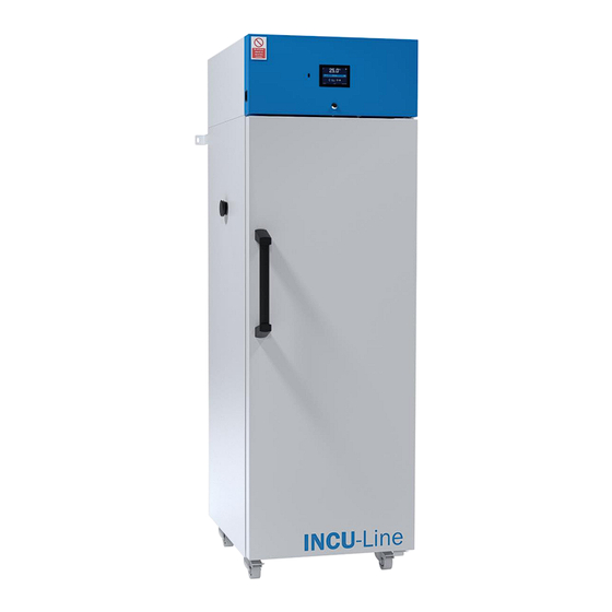
Summary of Contents for VWR avantor INCU-Line IL 500R
- Page 1 Instruction manual ® Cooled Incubator INCU-Line IL 500R European Catalogue Number: 390-1705 Version 2.4 Issue 03/2024...
- Page 2 Instruction Manual INCU-Line Cooled Incubator Legal address of Manufacturer Europe VWR International bv Researchpark Haasrode 2020 Geldenaaksebaan 464 B-3001 Leuven +3216385011 be.vwr.com Only for CE/UKCA marked products: UK Importer VWR International Ltd Hunter Boulevard, Magna Park Lutterworth, Leicestershire, LE17 4XN uk.vwr.com...
-
Page 3: Table Of Contents
Instruction Manual INCU-Line Cooled Incubator Contents INTENDED USE AND IMPORTANT INFORMATION FOR THE USER ......5 PACKAGE CONTENTS ....................6 BEFORE THE FIRST USE ..................... 6 3.1. Installation of shelves ....................8 3.2. Remarks on the type of samples ................8 3.3. - Page 4 Instruction Manual INCU-Line Cooled Incubator 5.10. Info ......................... 30 5.11. Interface ......................30 5.12. Time ....................... 31 5.13. Alarms ......................33 5.14. Network ......................34 5.15. Defrosting function ..................35 5.16. Corrections ..................... 36 COMPONENTS OF THE UNIT ..................37 6.1.
-
Page 5: Intended Use And Important Information For The User
Instruction Manual INCU-Line Cooled Incubator 1. INTENDED USE AND IMPORTANT INFORMATION FOR THE USER To guarantee your security and the longevity of the unit, please comply with the following rules: The unit cannot be installed: • outside, • in damp places or places which can be easily flooded, •... -
Page 6: Package Contents
Instruction Manual INCU-Line Cooled Incubator 2. PACKAGE CONTENTS INCU-Line 500R is delivered with the following equipment: 3 wire shelves with set of slides – 2 pcs. each, keys to the lock (2pcs.), manufacturer test certificate at 37 anchoring kit, multilingual instruction manual can be downloaded from internal memory on USB stick. Additional shelves and Premium Control software can be ordered separately: Description Quantity... - Page 7 Instruction Manual INCU-Line Cooled Incubator The electric installation should meet the following conditions The electrical installation must be protected with a 16 A fuse The device is powered by AC 230V/50Hz. Please connect it to a socket with ground in order to avoid electric shocks in case of the unit’s failure.
-
Page 8: Installation Of Shelves
Instruction Manual INCU-Line Cooled Incubator 3.1. Installation of shelves erform the following steps to adjust shelf height: 1) Install the shelf holder at the selected height by inserting it into appropriate slots on the sides. 2) Insert the shelf holder into the slots on one side. 3) Install the second shelf holder on the opposite chamber wall. -
Page 9: Remarks On The Placement Of Samples
Instruction Manual INCU-Line Cooled Incubator If water gathers, use a dry cloth to wipe the bottom of the chamber. Do not use any cardboard boxes, sponges and other hygroscopic materials for storing the samples since they may increase the relative humidity in the chamber. 3.3. -
Page 10: Anchoring The Equipment
Instruction Manual INCU-Line Cooled Incubator 3.5. Anchoring the equipment The IL 500R must be anchored to the wall using appropriate fixings (the anchoring kit is supplied with the incubator). This will prevent the unit from tipping over. Lack of anchoring may result in damage to the chamber and, in extreme cases, may pose a threat to the health or life of the person using the equipment. -
Page 11: Overview
Instruction Manual INCU-Line Cooled Incubator 4. OVERVIEW front view 1) USB socket 4) LED light 2) Electronic controller 5) Access port (Ø 30mm) on left side with 4.3” touch panel 6) Internal glass door 3) Door lock Shelf Page 11 / 50... - Page 12 Instruction Manual INCU-Line Cooled Incubator rear view 8) Monoblock cooling system 11) Main power switch 9) Fuse 12) LAN port 10) Socket power cable 13) Anchoring handle 14) Castors with brakes Page 12 / 50...
-
Page 13: Unit Operation
Instruction Manual INCU-Line Cooled Incubator 5. UNIT OPERATION This symbol means that a given field / window can be moved in the direction shown in the picture. 5.1. Internal memory During using the unit, it may be necessary to write or read the data from the external memory – a USB flashdrive. -
Page 14: Main Screen
Instruction Manual INCU-Line Cooled Incubator 5.3. Main Screen After switching on the device, the Main Screen (Figure appears. It contains the information about the device status. Figure 2 - Main Screen 5.3.1. Alarm bar The colour of the bar indicates the status of the device: –... - Page 15 Instruction Manual INCU-Line Cooled Incubator 5.3.2.1. Status Figure 3 - Status - icons Internal light is switched on Closed door, open door. The number above the icon presents open door counter, press the icon to cancel the counter. The counter is also cancelled during turning on the device Icon for the fan.
-
Page 16: Alarms Panel
Instruction Manual INCU-Line Cooled Incubator 5.3.3. Alarms panel In this place appears the list of alarms. With active alarm, the control bar is red. The alarm event is displayed in the list, with the status alarm active. When an alarm event stops, the alarm remains in the list as inactive. •... -
Page 17: Status Panel
Instruction Manual INCU-Line Cooled Incubator 5.3.4. Status panel The status of the device is indicated by description. Figure 7 – Status - description program name The name of program current segment Currently performing segment / total number of segments in the program »... -
Page 18: Programs
Instruction Manual INCU-Line Cooled Incubator 5.4. Programs In this panel (Figure 8) you can run the selected program, add a new one, edit the program or delete it. Menu push buttons: Run the selected program Stop the program Add a new program Edit the selected program Delete the selected program Figure 8 –... -
Page 19: Segments Edition
Instruction Manual INCU-Line Cooled Incubator • Priority – the priority of time or parameters, more information » chapter 5.4.5 • Loop – the number of program repetitions, more information » chapter 5.4.4 Figure 9 - Program parameters Cancels adding or editing of the program Switching to the edition of program segments 5.4.2. - Page 20 Instruction Manual INCU-Line Cooled Incubator Figure 10 - Program segment edition The ramp parameters are set to the values recommended by the manufacturer. If it is necessary to set individual parameters, activate the edit ramp field and set your own values. Figure 11 - Program segment edition The navigation between: segments, program parameters and summary is done by swiping up the segment with the finger or touch the icon...
-
Page 21: Summary Of Segments
Instruction Manual INCU-Line Cooled Incubator 5.4.3. Summary of segments In the summary in the figure all segments (Figure 12) are visible along with the entered settings: • segment number, • Temperature, duration time, target time of reaching temperature of a given segment. Figure 12 –... -
Page 22: Protection Class
Instruction Manual INCU-Line Cooled Incubator The program with a ramp – first, the device counts down the time of the ramp and then proceeds to the segment countdown when the set temperature is reached. Regardless of whether the time of ramp elapsed. It may happen that the device couldn’t reach the set temperature within the set time because the reaching time was too short. -
Page 23: Starting The Program
Instruction Manual INCU-Line Cooled Incubator » Chapter More information see 5.5. Starting the program You can start the program in two ways: The first way • „programs” in main menu Press the icon (Figure 14). • Then select the program you want to activate and press „Start” button (Figure 15). - Page 24 Instruction Manual INCU-Line Cooled Incubator • By pressing the icon you will go to the program selection window (Figure 17). • Select the program you want to activate, you have got two additional options: Immediate start of the program Scheduled program start according to the set date and time Figure 16 - Main screen Figure 17 - Starting the program It’s possible to start a backdated scheduled program but only for programs with time priority and...
-
Page 25: Quick Change Of Parameters
Instruction Manual INCU-Line Cooled Incubator 5.6. Quick change of parameters 5.6.1. Quick change set temperature In order to quickly change the value of the set temperature of a running program, press the icon in main screen (Figure The value of the temperature should be selected by scrolling the list up or down (Figure 18). -
Page 26: Statistics
Instruction Manual INCU-Line Cooled Incubator Figure 19 - Quick change of time Statistics 5.7. This panel displays statistics about the currently running program or program that has ended. Statistics are calculated separately for each segment and for a current cycle. Data logging starts for calculation after 30 seconds from reaching the set temperature in the segment. -
Page 27: Data Record
Instruction Manual INCU-Line Cooled Incubator Figure 20 - Statistic Data record 5.8. Register window (Figure 22) contains the following information: • Time and date of sample registration [date], • Temperature value from the main sensor in the chamber [temp.]. It is possible to register 10 000 data records to use for the max period of 6 months. If all the memory cells are full, the oldest ones are overwritten. -
Page 28: Event Log
Instruction Manual INCU-Line Cooled Incubator Figure 22 – Data Register Data recording onto the USB flash drive. .csv files are available - semicolon separated by opening eg with a spreadsheet, .plkx - opening with the Premium Control applica- tion Deleting data. Event log 5.9. - Page 29 Instruction Manual INCU-Line Cooled Incubator Saving the data onto USB flash drive. .csv files are available - semicolon separated by opening eg with a spreadsheet, .plkx - opening with the Premium Control application Deleting data Information event Alarm event Error Possible events: Date/time change data/time were changed...
-
Page 30: Info
Instruction Manual INCU-Line Cooled Incubator Info 5.10. The panel contains the following information: • Software versions, • name of device, • manufacturer’s address, • manufacturer’s website. Figure 24 – Info window to save the “Download” folder (with instruction manual) on the USB memory stick. Press icon - write the service data on the USB-stick –... -
Page 31: Time
Instruction Manual INCU-Line Cooled Incubator Figure 25 – Interface settings Confirms and saves changes Cancels the entered changes Time 5.12. In this panel you can: • change date / system time, • change time zone Date and time cannot be changed while the program is running. If you change the date and time to an earlier than the current one, a message will appear on the display: “Changing the date/time will interfere with the records in the database. - Page 32 Instruction Manual INCU-Line Cooled Incubator Figure 26 – Time Figure 27 – Date settings Confirms and saves changes Cancels the entered changes Page 32 / 50...
-
Page 33: Alarms
Instruction Manual INCU-Line Cooled Incubator The same time zones are required for correct operation of programs on the device and com- puter. Alarms 5.13. You can set parameters related to alarms. • lower alarm – an alarm will be generated if the temperature drops below the value given in this field •... -
Page 34: Network
Instruction Manual INCU-Line Cooled Incubator In the field "lower alarm temp" you can set a value of -1°C to - 5°C and in the field "upper alarm temp" you can set a value of +1°C to +5°C. Network 5.14. In this panel (Figure 29) you can change the settings for the LAN: •... -
Page 35: Defrosting Function
Instruction Manual INCU-Line Cooled Incubator 5.15. Defrosting function The cooling system of the IL 500R cooled incubator is based on a monoblock, in which the evaporator is defrosted with warm gases. This prevents it from frosting. The defrosting parameters should be defined in the program as described below. Default settings - 2 minutes (120s) defrosting every 2 hours, causes a temporary increase in tem- perature in the chamber. -
Page 36: Corrections
Instruction Manual INCU-Line Cooled Incubator Corrections 5.16. In this window (Figure 31) you can set temperature correction: • The temperature indicated on the display by adding the correction value. The set correction value is taken in the whole temperature range operation of the device. For example, if the average tempera- ture displayed by the device indicates 20,0°C and the average temperature measured by independ- ent, external sensor indicates 20,5°C, the correction should be set on +0,5°C. -
Page 37: Components Of The Unit
Instruction Manual INCU-Line Cooled Incubator 6. COMPONENTS OF THE UNIT 6.1. Internal glass door To open or close the internal glass door use the plastic handle installed on the glass. While operating the unit at high temperatures, do not touch the glass door or inner parts of the chamber. Always use safety gloves to protect yourself and minimise the risk of getting burnt. -
Page 38: Open Door Alarm
Instruction Manual INCU-Line Cooled Incubator 6.4. Open door alarm All incubators have been equipped with an open door sensor. If you open the door, icon: appear on the display. If you leave the door open for more than 60 seconds, an alarm will sound and the control bar will be red. The alarm event “door open”... - Page 39 Instruction Manual INCU-Line Cooled Incubator Press: Data is copied. Data saved as *.csv file can be opened in the Notepad. Data saved as *.plkx file can be opened only by optional available Premium Control Software. This program allows you f. ex. to view the data in the table as a graph.
-
Page 40: Temperature Protection
Instruction Manual INCU-Line Cooled Incubator 7. TEMPERATURE PROTECTION Temperature protection is included as standard, if damage occurs to the temperature controller or the user changes the temperature settings outside of the upper and lower limits, temperature protection will activate. rotection class 3.3 is a standard. The figure below shows how this works Protection Class 3.3. -
Page 41: Operation Of The Cooling System
Instruction Manual INCU-Line Cooled Incubator OPERATION OF THE COOLING SYSTEM If the unit is operating in low temperatures, the evaporator may get covered with ice what can affect the lower cooling efficiency of the device. The cooling system of the IL 500R cooled incubator is based on a monoblock in which the evaporator is defrosted with warm gases;... -
Page 42: Exterior Cleaning
Instruction Manual INCU-Line Cooled Incubator INOX products are manufactured with stainless steel. When used in standard laboratory conditions they do not rust. However it is possible that stains (which may look like rust) form on the steel surface (e.g. due to the kind of samples that are incubated in the chamber). -
Page 43: Interior Cleaning
• Complete technical service contact information • Access to VWR’s Online Catalogue, and information about accessories and related products • Additional product information and special offers Contact us for information or technical assistance contact your local VWR representative or visit www.vwr.com Page 43 / 50... -
Page 44: Possible Defects
Instruction Manual INCU-Line Cooled Incubator 12.1. Possible defects Malfunction What to check What to do The unit is not working Check the voltage in the socket Measure the voltage in the socket; if necessary, change the fuses in the electric installation in the building Check if the unit is plugged in Plug in the unit... -
Page 45: Warranty Conditions
VWR International warrants that this product will be free from defects in material and workmanship for a period of two (2) years from date of delivery. If a defect is present, VWR will, at its option and cost, repair, replace, or refund the purchase price of this product to the customer, provided it is returned during the war- ranty period. -
Page 46: Product Identification Label
Instruction Manual INCU-Line Cooled Incubator 14. PRODUCT IDENTIFICATION LABEL The product identification label is located in the upper left corner. Below there is an example of product identification label: 1. Logo 2. Type of unit 3. Catalogue number 4. Serial number 5. -
Page 47: Technical Details
Instruction Manual INCU-Line Cooled Incubator 15. TECHNICAL DETAILS IL 500R Air convection forced Chamber capacity [l] Door type double (external solid + internal glass) Temperature range [ºC] +3...+70 Temperature resolution [ºC] every 0,1 microprocessor with a 4,3” full colour touch screen Controller Interior stainless steel to DIN 1.4016... - Page 48 Instruction Manual INCU-Line Cooled Incubator IL 500R Page 48 / 50...
- Page 49 Instruction Manual INCU-Line Cooled Incubator Equipment disposal This equipment is marked with the crossed out wheeled bin symbol to indicate that this equipment must not be dis- posed of with unsorted waste. Instead it's your responsibility to correctly dispose of your equipment at lifecycle -end by handling it over to an authorized facility for separate collection and recycling.
- Page 50 Instruction Manual INCU-Line Cooled Incubator Local VWR offices in Europe and Asia Pacific Hungary Austria Poland VWR International Kft. VWR International GmbH VWR International Sp. z o.o. Simon László u. 4. Graumanngasse 7 Limbowa 5 4034 Debrecen 1150 Vienna 80-175 Gdansk Tel.: +36 (52) 521-130...
Need help?
Do you have a question about the avantor INCU-Line IL 500R and is the answer not in the manual?
Questions and answers