
Subscribe to Our Youtube Channel
Related Manuals for VWR 76019-132


Summary of Contents for VWR 76019-132
- Page 1 ® Centrifuge INSTRUCTION MANUAL North America Catalog Number 76019-132 76018-988 Version: Issued: 06-16-2017 VWR Collection CentrifugeV.1 08.16.2017...
- Page 2 VWR Collection CentrifugeV.1 08.16.2017...
- Page 3 Legal Address of Manufacturer United States Europe VWR International, LLC VWR International bvba 100 Matsonford Rd Researchpark Haasrode 2020 Radnor, PA 19087 Geldenaaksebaan 464 800-932-5000 B-3001 Leuven http://www.vwr.com + 32 16 385011 http://be.vwr.com Country of origin: China VWR Collection CentrifugeV.1...
-
Page 4: Table Of Contents
Table of Contents Copyright Safety Information Package Contents Intended Use Product Specifications Overview Description of Buttons and Switches Getting Started Rotor Preparation Operation Troubleshooting Repair and Maintenance Rotors and Tubes Technical Service Warranty Equipment Disposal VWR Collection CentrifugeV.1 08.16.2017... -
Page 5: Copyright
Copyright No part of this manual may be reproduced or transmitted without prior written permission of us. VWR Collection CentrifugeV.1 08.16.2017... -
Page 6: Safety Information
Warning Federal Communications Commission Advisory This equipment has been tested and found to comply with the limits for a Class A digital device, pursuant to part 15 of the FCC rules. These limits are designed to provide reasonable protection against harmful interference when the equipment is operated in a commercial environment. - Page 7 Do not operate the centrifuge in any manner not described in this User Manual. When in doubt or have any troubles with this centrifuge, ASK FOR HELP. The precautions described in this User Manual are carefully developed in an attempt to cover all the possible risks.
-
Page 8: Package Contents
Vibrations are likely to damage the centrifuge, contact our service center if abnormality is observed. Package Contents Description Quantity Centrifuge 1 each 15mL fixed angle rotor 1 each (with model 76019-132) Instruction Manual 1 each Power Cords 1 each 1 each 1 each... -
Page 9: Intended Use
Upon Receiving the Instrument Examine the unit carefully for any damage that may have occured during transit. Any damage claims must be filed with the carrier. The warranty does not cover in-transit damage. To ensure safe, reliable operation, always operate the 300V Hi Amperage Power Supply in accordance with the manufacturer’s instructions. -
Page 10: Product Specifications
Product Specifications Maximum speed 4500rpm(300-4500rpm), increment: 100rpm Maximum RCF 2490×g, increment: 100×g 76018-982 (plastic): 12x10ml, 8x15ml, 4500rpm (100-2490xg) Rotors 76018-976 (aluminum): 6x50ml, 4000rpm (100-1800xg) Timer 30seconds -99minutes-HOLD, continuous operation Deceleration curves Driving Motor Brushless DC motor Safety devices Door interlock, Over-speed detector, Automatic internal diagnosis Rotor Identification Single-phase, 100V-240V, 50Hz/60Hz, 3A. -
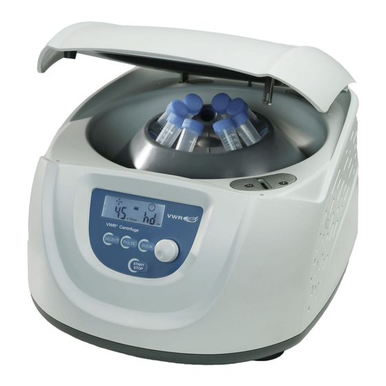
Page 11: Overview
Overview Required Operational Conditions Basic operational conditions (1)Power: 100V-240V, 50Hz/60Hz, 3A. (2)Ambient temperature: 2℃~40℃. (3)Relative humidity: ≤80%. (4)No vibration and airflow around. (5)No electric dust, explosive and corrosive gases around. Transport and storage conditions (1)Storage temperature: -40℃~55℃. (2)Relative humidity: ≤93%. Door lock hook Rotor Door release hole... - Page 12 View Air vents Door hole Power inlet Power switch Figure 6-2 Rear view of the centrifuge Operation Panel Figure 7-1 Operation panel Item Symbol Name Function Select button Press the buttonto choose the program which you want to modify. The speed can be accelerated and held at the speed when Pulse button pressing Pulse on.
-
Page 13: Rotor Preparation
Push the KEY and hold on for more than 7 seconds, set the deceleration curve, see “Deceleration curve setting”in page 14 Speed area Lock status Time area ×100rpm Figure 7-2 The main interface Main interface is as figure 7-2. The speed is set to be 4500rpm, the door lock is released and the running time is 12 minutes. -
Page 14: Operation
Only VWR’s rotors must be used with the unit. 5 Symmetrically load centrifuge tubes into rotor CAUTION Make sure the rotor lid is securely fixed on the rotor, as well as the rotor and shaft are tightened. Otherwise, the rotor may lift off while rotating and cause damage to the centrifuge and rotor. - Page 15 (1)Set the speed Press the select button until the speed rpm is displayed. When the speed button is selected, the speed symbol will flash the speed value. The minimum speed value you can set 300rpm, the minimum increment is 100 rpm. ...
- Page 16 table 11-1, and corrective actions can be applied accordingly. Deceleration curve setting Two deceleration curves can be set, a fast stop and slow stop. Brake step 1 Press the button and hold for more than 7 seconds, F will display on the LCD, then press the button again.
- Page 17 (3)Set operating conditions For other operation, please refer to the section 8.1. 3 Pulse operation This function is used to remove the residual samples adhered to the interior of the tubes or for quick spins. Note:The button works only while the rotor stopped and the door is locked. ...
- Page 18 CAUTION Do not directly pour water, neutral detergent or disinfectant solution into the rotor chamber, otherwise fluids may leak into the drive units and cause corrosion or deterioration to the bearings. If the rotor needs cleaning, clean with cloth or sponge moistened with a neutral detergent solution.
- Page 19 ④ ⑤ (2) Adjustment NOTE! Before locking the rotor, rotate it, and observe carefully if there is obvious vibration, if so, please remove the rotor, turn slightly and install again until the rotor rotates smoothly, then, lock it firmly. How to open the lid 1) In the case of power on CAUTION ...
- Page 20 Insert a screw driver into the hole and push forward to release the lid. Instructions for the rotor and tubes CAUTION Read the instructions thoroughly, to properly load and use rotor. Do not exceed the allowable maximum speed of rotor、tube and adapters etc. Ensure the allowable maximum speed of adapters is lower than the rotor’s maximum speed.
- Page 21 Table 12-1 Rotors and adapters 3) 6 x 50ml Rotor (76018-976) Instruction manual Fixed angle rotor for 76019-132 Centrifuge 76018-976 rotor body 6-50ml tube 76018-978 adapter Safety Reminder Centrifuge rotors rotating at high speed have considerable potential for damage to personal properties if used improperly.
- Page 22 Conical 76018-978 1.5-5ml 13×82 76018-984 4000 1521 vacu 76018-986 76018-978 1700 13×106 76018 76018-984 -976 4-7ml vacu 4000 76018-978 16×75 76018-984 1521 76018-986 8.5-10 ml 76018-978 1700 16×107 4000 vacu 76018-984 2.7-3 (EU) 76018-978 11×66 76018-984 4000 1521 collection 76018-986 tube 7.5-8.2 (EU) ml...
- Page 23 4) Notice The centrifuge rotor can separate samples with a density lower than 2.0g/ml.If the samples density is over 2.0g/ml, please calculate allowable speed depending on the following formula. ( 0 speed llow speed( ample density( 5) Autoclaving 76018-982 rotor is made of plastic, cannot be high-pressure sterilization and UV irradiation, only ordinary sterilization can be used.
- Page 24 2 Tubes Cleaning and sterilizing tubes O:Applicable X:Inapplicable ConditionsMaterials Acidic(pH5 or lower) Acidic(higher than pH5 ) Alkaline(higher than pH9 ) Cleaning fluids Alkaline(pH9 or lower) Neutral(pH7) Warm water(up to 70℃) Ultrasonic cleaning Neutral detergent(pH7) )30minutes 115℃(0.7kg/cm )20 minutes Autoclaving 121℃(1.0kg/cm )15 minutes 126℃(1.4kg/cm Boiling...
- Page 25 (2) Remove locking nut and lid to prevent from deformation or rupture. (3) Wait until the sterilizing chamber cools down to the room temperature before removing tubes. 4) Conditions and life expectancy of tubes The life expectancy of plastic tubes depends on the characteristics of samples, speed of the rotor used, temperature applied and so on.
-
Page 26: Troubleshooting
• Complete technical service contact information. • Access to VWR’s Online Catalog, and information about accessories and related products. • Additional product information and special offers. Contact Us For information or technical assistance contact your local VWR representative or visit. -
Page 27: Warranty
(1) year from date of purchase. If a defect is present, VWR will, at its option, repair, replace, or refund the purchase price of this product at no charge to you, provided it is returned during the warranty period. - Page 28 equipment must not be disposed of with unsorted waste. Instead it's your responsibility to correctly dispose of your equipment at lifecycle -end by handling it over to an authorized facility for separate collection and recycling. It's also your responsibility to decontaminate the equipment in case of biological, chemical and/or radiological contamination, so as to protect from health hazards the persons involved in the disposal and recycling of the equipment.
Need help?
Do you have a question about the 76019-132 and is the answer not in the manual?
Questions and answers