Table of Contents
Advertisement
Quick Links
F132-P
BATCH-CONTROLLER
WITH RECEIPT PRINTER DRIVER
Signal input flowmeter type P: pulse, Namur and coil
Status inputs: start and stop
Control output: two control outputs for one- and two-stage control
Communication: Printer interface for receipt printing
Options: Intrinsically Safe
F-Series - Field mounted indicators for safe and hazardous areas. More info: www.fluidwell.com/fseries
Advertisement
Table of Contents

Related Manuals for Fluidwell F132-P


Summary of Contents for Fluidwell F132-P
- Page 1 Signal input flowmeter type P: pulse, Namur and coil Status inputs: start and stop Control output: two control outputs for one- and two-stage control Communication: Printer interface for receipt printing Options: Intrinsically Safe F-Series - Field mounted indicators for safe and hazardous areas. More info: www.fluidwell.com/fseries...
-
Page 2: Safety Instructions
This unit must be installed in accordance with the EMC guidelines (Electro Magnetic Compatibility). Do connect a proper grounding to the aluminum casing as indicated if the F132-P has been supplied with the 115-230V AC power-supply type PM. The green / yellow wire between the back-casing and removable terminal-block may never be removed. -
Page 3: About The Operation Manual
This operation manual describes the standard unit as well as most of the options available. For additional information, please contact your supplier. A hazardous situation may occur if the F132-P is not used for the purpose it was designed for or is used incorrectly. Please carefully note the information in this operating manual indicated by the pictograms: A "warning"... -
Page 4: Table Of Contents
Safety rules and precautionary measures ....................... 2 About the operation manual ..........................3 Contents manual .............................. 4 Introduction ..........................5 1.1. System description of the F132-P ..................5 Operational ..........................7 2.1. General ..........................7 2.2. Control panel .......................... 7 2.3. -
Page 5: Introduction
SYSTEM DESCRIPTION OF THE F132-P Functions and features The batch controller model F132-P is a microprocessor driven instrument designed for batching and filling of small batch sizes up to large quantities as well as displaying total and accumulated total. This product has been designed with a focus on: ... - Page 6 Page 6 Configuration of the unit The F132-P was designed to be implemented in many types of applications. For that reason, a SETUP-level is available to configure your F132-P according to your specific requirements. SETUP includes several important features, such as K-factors, measurement units, signal selection etc.
-
Page 7: Operational
30 second period, after which it will slow-down again. If you start a procedure but do not finish it, or you don’t touch a key for 20 seconds, the F132-P will automatically return to Operator level without making changes. - Page 8 Page 8 SET-UP PAUSE READY PROGRAM ALARM LOW BATTE RY Fig. 4: Example display during programming preset value. Note that a PRESET-value will be used time after time until a new value is accepted. Please note that changes will only be accepted after ENTER has been pressed briefly! ...
-
Page 9: Operator Alarms
Fig. 7: Example display showing low-battery alarm. No-flow alarm The F132-P offers a no-flow monitoring feature: When the flowmeter fails to generate a signal during a certain (preset) time period, the unit will shut-off the control output(s) and bring the batch controller in alarm status. -
Page 10: Configuration
Operating Manual before carrying out its instructions. The F132-P may only be operated by personnel who are authorized and trained by the operator of the facility. All instructions in this manual are to be observed. - Page 11 Page 11 Matrix structure SETUP-level: SCROLLING THROUGH SETUP-LEVEL Selection of function-group and function: SETUP is divided into several function groups and functions. Each function has a unique number, which is displayed below SETUP at the bottom of the display. The number is a combination of two figures. The first figure indicates the function-group and the second figure the sub-function.
- Page 12 Page 12 To change or select a value: To change a value, use ► to select the digits and ▲ to increase that value. To select a setting, both ▲ and ► can be used. If the new value is invalid, the increase sign ▲ or decrease-sign ▼ will be displayed while you are programming.
-
Page 13: Overview Functions Setup Level
STARTROW 0 – 9 ENDROW 0 – 9 FORMFEED enable - disable DATEFORMAT Y.M.D - D.M.Y - M.D.Y OTHERS TYPE / MODEL F132-P (fixed) SOFTWARE VERSION 02.05.xx (fixed) SERIAL NO. XXXXXXXX (fixed) TIME HH:MM:SS (24 hour format) DATE 20YY:MM:DD PASSWORD... -
Page 14: Explanation Of Setup-Functions
Page 14 3.2.3. EXPLANATION OF SETUP-FUNCTIONS 1 - PRESET SETUP 11 determines the measurement unit for preset, total, accumulated MEASUREMENT UNIT total and pulse output. The following units can be selected: L - m3 - kg - lb. - GAL - USGAL - bbl - _ (no unit). -
Page 15: Overrun
The minimum overrun time is 0.1 second, maximum 999.9 seconds. 3 - ALARM The F132-P offers a no-flow monitoring feature: if the flowmeter fails to generate a signal during a certain period of time, the unit will shut-off the control output(s) and bring the batch controller in alarm status. -
Page 16: Flowmeter
Page 16 6 - FLOWMETER The F132-P is able to handle several types of input signal. The type of SIGNAL flowmeter pickup / signal is selected with SETUP 61. Note: The selections "active pulse" offer a detection level of 50% of the supply voltage. -
Page 17: Others
Page 17 Each receipt starts with a 16 character upper case text header. To HEADER customize the header text do the following: • Press PROG briefly; PROGRAM starts blinking • Optionally press ▲ and ► simultaneously to blank the header and/or •... -
Page 18: Installation
Personnel must read and understand this Operating Manual before carrying out its instructions. The F132-P may only be operated by personnel who are authorized and trained by the operator of the facility. All instructions in this manual are to be observed. ... -
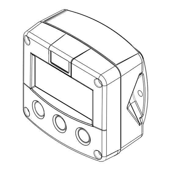
Page 19: Dimensions- Enclosure
Page 19 4.3. DIMENSIONS- ENCLOSURE Aluminum enclosures: 75 mm (2.95") 112 mm (4.40") 130 mm (5.12") 12mm 12mm 30mm 30mm 24mm 24mm M20 x 1,5 6 x M12 36mm 36mm 30mm 30mm M16 x 1,5 M16 x 1,5 1/2"NPT M20 x 1,5 0.12"... - Page 20 Page 20 GRP enclosures: 75 mm (2.95") 112 mm (4.40") 130 mm (5.12") HK back box: (flat bottom) 75 mm (2.95") 118 mm (4.65”) 25mm 25mm D=20mm D=20mm 12mm 12mm 30mm 30mm 24mm 24mm D=12mm D=16mm D=16mm D=20mm 36mm 36mm 0.12”...
-
Page 21: Installing The Hardware
Do ground the aluminum enclosure properly as indicated, if the F132-P has been supplied with the 115-230V AC power-supply type PM. The green / yellow wire between the back-casing and removable terminal-block may never be removed. -
Page 22: Voltage Selection Sensor Supply
A circuit board with four mini switches is now visible. Depending on the type of F132-P you will find the switches either on the left side (type PD) or on the right side (type PF / PM) of the circuit board. See figure 11 below for details. -
Page 23: Terminal Connectors
OA / OT / OR SIGNAL START STOP Fig. 12: Overview of terminal connectors standard configuration F132-P and options. REMARKS: TERMINAL CONNECTORS: Terminal GND- 01- 02: Power Supply - only available with type PD / PF or PM: erminal SENSOR SUPPLY PD 8-24V AC 8,2 / 12 / 24V max. - Page 24 Page 24 Terminal 03-04; control output R2: This output is available to control the batch process in two-step control mode. Terminal 05-06; control output R1: This output is available to control the batch process. Relay 1 is switched-on during the whole batch process.
- Page 25 SETUP-function (see par. 3.2.3.) Sine-wave signal (Coil): The F132-P can be connected to flowmeters that have a coil output signal. With SETUP 61 two sensitivity levels can be selected (see par. 3.2.3.): COIL LO: sensitivity from about 120mVp-p.
- Page 26 - read par. 3.2.3. Pulse-signal PNP / PNP-LP: The F132-P can be connected to flowmeters that have an PNP output signal. 3.2V is offered on terminal 11 which has to be switched by the sensor to terminal 10 (SIGNAL). For a reliable pulse detection, the pulse amplitude has to go above 1.2V.
- Page 27 Page 27 Reed-switch: The F132-P can be connected to flowmeters that have a reed-switch. To avoid pulse bounce from the reed-switch, it is advised to select REED LP - low-pass filter (see par. 3.2.3.) NAMUR-signal: The F132-P can be connected to flowmeters with a Namur signal. A battery powered F132-P is unable to power the Namur sensor.
- Page 28 Page 28 Terminal 15-16; external STOP: With this function, the batch controller can be interrupted or cancelled with an external switch. The input must be switched once for interruption or switch twice for cancellation with a potential free contact to the GND-terminal number 15 for at least 0.3 seconds. Terminal 26-31: type CB / CH / CI / CT –...
-
Page 29: Intrinsically Safe Applications
Please Note Certificates, safety values and declaration of compliance can be found in the document named: “Fluidwell F1..-..-XI - Documentation for Intrinsic Safety”. Special conditions for safe use mentioned in both the certificate and the installation instructions must be observed for the connection of power to both input and / or output circuits. -
Page 30: Terminal Connectors Intrinsically Safe Applications
Indicated labels on the back cover (below) and on the inside cover (right) show the type labels for intrinsically safe certified units. For details on usage see the separate “Fluidwell F1..-..-IX Documentation for Intrinsic Safety”. Serial number and year of production This information can be looked-up on the display: See setup function (par. - Page 31 Page 31 Explanation Intrinsically Safe options: Type PD - Intrinsically Safe power supply and sensor supply - Terminal GND- 01 and 11. erminal SENSOR SUPPLY output voltage is according Input voltage: the input voltage; internally 3,2 - 8,1V 16-30V DC linked with terminal 01.
-
Page 32: Configuration Examples Intrinsically Safe Applications
Page 32 5.3. CONFIGURATION EXAMPLES INTRINSICALLY SAFE APPLICATIONS Configuration example IIB /IIIC F132-P-CT-OT-PX-XI HAZARDOUS AREA SAFE AREA TERMINAL CONNECTORS F100-series RECEIPT PRINTER Modbus communication type CT: TTL I.S. Certified Isolator TTL to: = max. 30 V RS232 = max. 250 mA RS422 = max. -
Page 33: Battery Replacement Instructions
Batteries for use in safe areas have no Ex label. DO NOT EXCHANGE: Using the wrong type of battery can pose a SERIOUS RISK. For use in hazardous areas Fluidwell recommends FW-LiBAT batteries (manufactured by Fluidwell bv) only. Battery replacement procedure Depending on the production batch, one of two visualized Intrinsically Safe certified battery types may have been installed in the unit. -
Page 34: Maintenance
Operating Manual before carrying out its instructions. The F132-P may only be operated by personnel who are authorized and trained by the operator of the facility. All instructions in this manual are to be observed. -
Page 35: Appendix A: Technical Specification
Page 35 APPENDIX A: TECHNICAL SPECIFICATION GENERAL Display Type High intensity reflective numeric and alphanumeric LCD, UV-resistant. Digits Seven 17mm (0.67") and eleven 8mm (0.31"). Various symbols and measuring units. Refresh rate User definable: 8 times/sec - 30 secs. Type ZB Transflective LCD with green LED backlight. - Page 36 Page 36 Sensor excitation Type PB / PC / PX 3.2V DC for pulse signals and 1.2V DC for coil pick-up. Note: This is not a real sensor supply. Only suitable for pulse sensors with a very low power consumption like coils (sine wave) and reed-switches. Type PD 1.2 / 3.2 / 8.2 / 12 and 24V DC - max.
- Page 37 Page 37 OUTPUTS Control outputs Function User defined: batch process with one stage control or two stage control. Type OA Two active 24V DC transistor outputs; max. 50mA per output (requires type PD, PF or PM). Type OR Two mechanic relay outputs; max. switch power 230V AC - 0,5A (requires type PF or PM). Type OT Two passive transistor outputs - not isolated.
-
Page 38: Appendix B: Troubleshooting
Type of signal selected with actual signal generated - SETUP 61, Sensitivity of coil input SETUP 61 and par. 4.4.3. Proper grounding of the F132-P and flowmeter - par. 4.4.1. Pulse output does not function: Check: SETUP 71 - pulse per “x” quantity; is the value programmed reasonable and will the maximum output be under 20Hz? ... -
Page 39: Index Of This Manual
Page 39 INDEX OF THIS MANUAL accumulated Total pause active output power supply 23, 25 actual settings power supply intrinsically safe alarm preset batch maximum max. batch size battery life time 15, 34 Preset Cancel batch maximum Clear Total enter batch value clock printer 6, 9, 13, 16, 38... - Page 40 01:01:01 96 pass code 0000 97 tagnumber 0000000 Fluidwell bv HF132PEN_v0501_05 PO box 6 Voltaweg 23 Website: www.fluidwell.com 5460 AA Veghel 5466 AZ Veghel Find your nearest representative: www.fluidwell.com/representatives The Netherlands The Netherlands Copyright Fluidwell bv - 2012 - HF110AEN_v0501_03...
Need help?
Do you have a question about the F132-P and is the answer not in the manual?
Questions and answers