Table of Contents
Advertisement
Quick Links
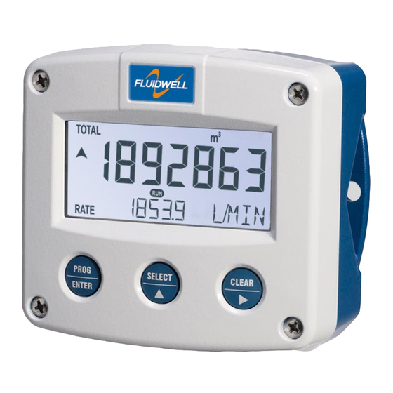
F124-P
Ratio controller
Signal input flowmeter: pulse, Namur and coil.
Control output: (0)4-20mA/ 0-10V.
Alarm outputs: high / low ratio alarm.
Options: Intrinsically Safe, Modbus communication and backlight.
F-Series - Field mounted indicators for safe and hazardous areas. More info: www.fluidwell.com/fseries
Advertisement
Table of Contents

Related Manuals for Fluidwell F124-P


Summary of Contents for Fluidwell F124-P
- Page 1 Ratio controller Signal input flowmeter: pulse, Namur and coil. Control output: (0)4-20mA/ 0-10V. Alarm outputs: high / low ratio alarm. Options: Intrinsically Safe, Modbus communication and backlight. F-Series - Field mounted indicators for safe and hazardous areas. More info: www.fluidwell.com/fseries...
-
Page 2: Safety Instructions
This unit must be installed in accordance with the EMC guidelines (Electro Magnetic Compatibility). Do connect a proper grounding to the aluminum casing as indicated if the F124-P has been supplied with the 115-230V AC power-supply type PM. The green / yellow wire between the back-casing and removable terminal-block may never be removed. -
Page 3: About The Operation Manual
This operation manual describes the standard unit as well as most of the options available. For additional information, please contact your supplier. A hazardous situation may occur if the F124-P is not used for the purpose it was designed for or is used incorrectly. Please carefully note the information in this operating manual indicated by the pictograms: A "warning"... -
Page 4: Table Of Contents
Safety rules and precautionary measures ....................... 2 About the operation manual ..........................3 Contents manual .............................. 4 Introduction ..........................5 1.1. System description of the F124-P ..................5 Operational ..........................7 2.1. General ..........................7 2.2. Control panel .......................... 7 2.3. -
Page 5: Introduction
INTRODUCTION 1.1. SYSTEM DESCRIPTION OF THE F124-P Functions and features The PI ratio controller model F124-P is a microprocessor driven instrument designed to control the ratio between two flows. This product has been designed with a focus on: ultra-low power consumption to allow long-life battery powered applications (type PB / PC), ... - Page 6 Page 6 Configuration of the unit The F124-P was designed to be implemented in many types of applications. For that reason, a SETUP-level is available to configure your F124-P according to your specific requirements. SETUP includes several important features, such as K-factors, measurement units, signal selection etc.
-
Page 7: Operational
Take careful notice of the " Safety rules, instructions and precautionary measures " in the front of this manual. This chapter describes the daily use of the F124-P. This instruction is meant for users / operators. 2.2. CONTROL PANEL... -
Page 8: Operator Information And Functions
SETUP-settings. All pulses generated by the connected flowmeter are measured by the F124-P in the background, whichever screen refresh rate setting is chosen. After pressing a key, the display will be updated very quickly during a 30 second period, after which it will slow-down again. - Page 9 Page 9 “Local” mode In this mode the local set-point B can be set, corresponding with the process value of flow transmitter B (additive). The set-point can be changed, using the “” button (UP) and the “” button (down). Both set-point and process value are displayed as a percentage.
- Page 10 Page 10 Low-battery alarm When the battery voltage drops, it must be replaced. At first "low-battery" will flash, but as soon as it is displayed continuously, the battery MUST be replaced shortly after! Only original batteries supplied by the manufacturer may be used, else the guarantee and liability will be terminated.
-
Page 11: Configuration
Operating Manual before carrying out its instructions. The F124-P may only be operated by personnel who are authorized and trained by the operator of the facility. All instructions in this manual are to be observed. - Page 12 Page 12 Matrix structure SETUP-level: SCROLLING THROUGH SETUP-LEVEL Selection of function-group and function: SETUP is divided into several function groups and functions. Select function-group with SELECT Select function with Each function has a unique number, which is displayed below the word "SETUP" at the bottom of the display.
- Page 13 Page 13 To change or select a value: PROG a) press briefly; will start flash PROGRAM ENTER b) select or enter value with and / or SELECT PROG c) press to confirm the value / selection. ENTER b) b) To change a value, use to select the digits and to increase that value. To select a setting, both ...
-
Page 14: Overview Functions Setup Level
0 - 9,999 (=100%) COMMUNICATION SPEED / BAUDRATE 1200 - 2400 - 4800 - 9600 ADDRESS 1 - 255 MODE RTU - off OTHERS TYPE / MODEL F124-P SOFTWARE VERSION xx.xx.xx SERIAL NO. Xxxxxxx PASSWORD 0000 – 9999 TAGNUMBER 0000000 – 9999999 HF124PEN_v0501_04... -
Page 15: Explanation Of Setup-Functions
Page 15 3.2.3. EXPLANATION OF SETUP-FUNCTIONS 1 - FLOWRATE “A” The settings for flowrate A (main flow) and flowrate B (additive) are common, with the exception of the K-Factor settings. SETUP - 11 determines the measurement unit for flowrate for flow A: MEASUREMENT UNIT mL, L, m3, mg, g, kg, ton, GAL, bbl, lb, cf, rev, no unit, SCF, nm3, nL, P... -
Page 16: Flowrate "B
I-TIME Setting range : 0.0 – 6000.0 seconds (value 0.0 seconds disables this (IT SEC) function) This function allows the F124-P to start-up after a power-shutdown in a STARTUP safe mode. Three selections can be made: Safety: it continues with the safety value as programmed with SETUP 83. -
Page 17: Alarm
When used with the internal battery option, the user can expect reliable measurement over a long period of time. The F124-P has several smart power management functions to extend the battery life time significantly. Two of these functions can be set:... -
Page 18: Flowmeter
Page 18 7 - FLOWMETER The F124-P is able to handle several types of input signal. SIGNAL A The type of flowmeter pickup / signal for input A “main flow” is selected with SETUP 71. Note: The selections "active pulse" offer a detection level of 50% of the supply voltage. -
Page 19: Analog Output
Page 19 8 - ANALOG OUTPUT A linear analog (0)4-20mA / 0-10V signal is generated to control the ratio between flow A and B. The range of the analog output is set with the following functions: With this function, the value for the minimum control output is set. CONTROL OUTPUT The value has to be entered as a percentage of the maximum output CO MIN - LOW LIMIT... -
Page 20: Communication (Optional)
1200 - 2400 - 4800 - 9600 baud For communication purposes, a unique identity can be attributed to every BUS ADDRESS F124-P-P. This address can vary from 1-255. The communication protocol is Modbus RTU mode. MODE Select OFF, to disable this communication function. -
Page 21: Installation
Personnel must read and understand this Operating Manual before carrying out its instructions. The F124-P may only be operated by personnel who are authorized and trained by the operator of the facility. All instructions in this manual are to be observed. ... -
Page 22: Dimensions- Enclosure
Page 22 4.3. DIMENSIONS- ENCLOSURE Aluminum enclosures: 75 mm (2.95") 112 mm (4.40") 130 mm (5.12") 12mm 12mm 30mm 30mm 24mm 24mm M20 x 1,5 6 x M12 36mm 36mm 30mm 30mm M16 x 1,5 M16 x 1,5 1/2"NPT M20 x 1,5 0.12"... - Page 23 Page 23 GRP enclosures: 75 mm (2.95") 112 mm (4.40") 130 mm (5.12") HK back box: (flat bottom) 75 mm (2.95") 118 mm (4.65”) 25mm 25mm D=20mm D=20mm 12mm 12mm 30mm 30mm 24mm 24mm D=12mm D=16mm D=16mm D=20mm 36mm 36mm 0.12”...
-
Page 24: Installing The Hardware
Do ground the aluminum enclosure properly as indicated, if the F124-P has been supplied with the 115-230V AC power-supply type PM. The green / yellow wire between the back-casing and removable terminal-block may never be removed. -
Page 25: Voltage Selection Sensor Supply
Page 25 4.4.2. VOLTAGE SELECTION SENSOR SUPPLY Type PB / PC / PX (AP) - battery powered and output loop-powered applications: Terminal 11 provides a limited supply voltage of 3.2 V DC (coil signals 1.2V) for the signal output of the flowmeter. -
Page 26: Terminal Connectors
PULSE INPUT INPUT SIGNAL SIGNAL SIGNAL Fig. 10: Overview of terminal connectors standard configuration F124-P and options. REMARKS: TERMINAL CONNECTORS: Terminal GND- 01- 02: Power Supply - only available with type PD / PF or PM: erminal SENSOR SUPPLY PD 8-24V AC 8,2 / 12 / 24V max. - Page 27 Page 27 Terminal 05-06; transistor or relay output R1: This output is high ratio alarm output. With SETUP 5, the function of this output is set. Terminal 03-04; transistor or relay output R1: This output is low ratio alarm output. With SETUP 5, the function of this output is set. Type OA: An active 24V DC signal output is available with this option.
- Page 28 Page 28 Type OT: A passive transistor output is available with this option. Max. driving capacity 300mA@50V DC. Terminal 07-08; basic POWER SUPPLY - type PX - output loop powered: Connect an external power supply of 8-30VDC to these terminals or a 4-20mA loop. Do connect the "-"...
- Page 29 Page 29 Type AB: An active 0-20mA signal control output is available with this option. Max. driving capacity 1000 Ohm @ 24VDC. (Requires power supply type PD / PF / PM). Type AI: An isolated passive 4-20mA signal control output is available with this option. Max.
- Page 30 SETUP-function (read par. 3.2.3.) Sine-wave signal (Coil): The F124-P is suitable for use with flowmeters which have a coil output signal. Two sensitivity levels can be selected with the SETUP-function: COIL LO: sensitivity from about 120mVp-p.
- Page 31 Pulse-signal PNP / PNP-LP: The F124-P is suitable for use with flowmeters which have a PNP output signal. 3.2V is offered on terminal 11 which has to be switched by the sensor to terminal 10 (SIGNAL). For a reliable pulse detection, the pulse amplitude has to go above 1.2V.
- Page 32 REED LP - low-pass filter (read par. 3.2.3.) NAMUR-signal: The F124-P is suitable for flowmeters with an Namur signal. The standard F124-P is not able to power the Namur sensor, as an external power supply for the sensor is required. However, a 8.2V sensor supply voltage (terminal 11) can be provided with power supply type PD, PF, PM.
- Page 33 Page 33 Terminal 12-14; Flowmeter input B (additive): Exactly as described for the flowmeter A, three basic types of flowmeter signals can be connected for flowmeter input B. Please refer to the descriptions per flowmeter type as describer for flowmeter A.
- Page 34 Page 34 Terminal 26-31: type CB / CH / CI / CT - communication RS232 / RS485 / TTL (option) Full serial communications and computer control in accordance with RS232 (length of cable max. 15 meters) or RS485 (length of cable max. 1200 meters) is possible. ...
-
Page 35: Intrinsically Safe Applications
Please Note Certificates, safety values and declaration of compliance can be found in the document named: “Fluidwell F1..-..-XI - Documentation for Intrinsic Safety”. Special conditions for safe use mentioned in both the certificate and the installation instructions must be observed for the connection of power to both input and / or output circuits. -
Page 36: Terminal Connectors Intrinsically Safe Applications
Indicated labels on the back cover (below) and on the inside cover (right) show the type labels for intrinsically safe certified units. For details on usage see the separate “Fluidwell F1..-..-IX Documentation for Intrinsic Safety”. Serial number and year of production This information can be looked-up on the display: See setup function (par. - Page 37 Page 37 Explanation Intrinsically Safe options: Type AF - Intrinsically Safe floating 4-20mA analog output - Terminal 7-8: A floating 4-20mA signal control output is available with this option. When the output is disabled, a 3.5mA signal will be generated. Max.
- Page 38 Page 38 5.3. CONFIGURATION EXAMPLES INTRINSICALLY SAFE APPLICATIONS Configuration example IIB /IIIC F124-P-AP-CT-OT-PX-XI HAZARDOUS AREA SAFE AREA TERMINAL CONNECTORS F100-series Modbus communication type CT: TTL I.S. Certified Isolator TTL to: = max. 30 V RS232 = max. 250 mA RS422 = max.
- Page 39 Page 39 Configuration example IIB/IIIC and IIC - F124-P-AP-(CT)-OT-PD-XI HAZARDOUS AREA SAFE AREA TERMINAL CONNECTORS F100-series Modbus communication type CT: TTL Please note: communciation type CT is allowed in IIC applications. I.S. Certified Isolator TTL to: = max. 30 V e.g.
-
Page 40: Battery Replacement Instructions
Batteries for use in safe areas have no Ex label. DO NOT EXCHANGE: Using the wrong type of battery can pose a SERIOUS RISK. For use in hazardous areas Fluidwell recommends FW-LiBAT batteries (manufactured by Fluidwell bv) only. Battery replacement procedure Depending on the production batch, one of two visualized Intrinsically Safe certified battery types may have been installed in the unit. -
Page 41: Maintenance
Operating Manual before carrying out its instructions. The F124-P may only be operated by personnel who are authorized and trained by the operator of the facility. All instructions in this manual are to be observed. -
Page 42: Appendix A: Technical Specification
Page 42 APPENDIX A: TECHNICAL SPECIFICATION Type High intensity reflective numeric and alphanumeric LCD, UV-resistant. Digits Seven 17mm (0.67") and eleven 8mm (0.31"). Various symbols and measuring units. Refresh rate User definable: 8 times/sec - 30 secs. Type ZB Transflective LCD with green LED backlight. Good readings in full sunlight and darkness. Note: only available for safe area applications. - Page 43 Page 43 Sensor excitation Type PB / PC / PX 3.2V DC for pulse signals and 1.2V DC for coil pick-up. Note: This is not a real sensor supply. Only suitable for pulse sensors with a very low power consumption like coils (sine wave) and reed-switches. Type PD 1.2 / 3.2 / 8.2 / 12 and 24V DC - max.
- Page 44 Page 44 OUTPUTS Analog output Function IP Control output. Accuracy 10 bit. Error < 0.05% - update 10 times a second. Software function to calibrate the 4.00mA and 20.00mA levels precisely within set-up. Load max. 1 kOhm Type AA Active 4-20mA output (requires type OA + PD, PF or PM). Type AB Active 0-20mA output (requires type OA + PD, PF or PM).
-
Page 45: Appendix B: Problem Solving
Page 45 APPENDIX B: PROBLEM SOLVING In this appendix, several problems are included that can occur when the F124-P is going to be installed or while it is in operation. The pass code is unknown: If the pass code is not 1234, there is only one possibility left: call your supplier. -
Page 46: Index Of This Manual
Page 46 INDEX OF THIS MANUAL actual settings Intrinsically Safe options Additive flowmeter IP classification alarm keys Alarm - ratio low limit alarm output Low limit analog low-battery floating output. main-function intrinsically safe output. maintenance model output loop powered. tune / calibrate Model Analog output NAMUR-signal... -
Page 47: List Of Figures In This Manual
Fig. 8: Grounding aluminum enclosure with type PM 115-230V AC..........24 Fig. 9: Switch setting sensor supply voltage..................25 Fig. 10: Overview of terminal connectors standard configuration F124-P and options..... 26 Fig. 11: Overview terminal connectors communication option............34 Fig. - Page 48 A3 serial number A4 pass code 0000 A5 tagnumber 0000000 Fluidwell bv HF124PEN_v0501_04 PO box 6 Voltaweg 23 Website: www.fluidwell.com 5460 AA Veghel 5466 AZ Veghel Find your nearest representative: www.fluidwell.com/representatives The Netherlands The Netherlands Copyright Fluidwell bv - 2012 - HF110AEN_v0501_03...
Need help?
Do you have a question about the F124-P and is the answer not in the manual?
Questions and answers