
Related Manuals for Astralpool Control Connect-PH/ORP line


Summary of Contents for Astralpool Control Connect-PH/ORP line
- Page 1 Control Connect ºC Instruction Manual Models Control panel for swimming pools Control Connect-PH/ORP_line Control Connect-PH/ORP_Pro Control Connect-PH/ppm_Pro Ver.20240429...
- Page 2 Instruction Manual PAGE 3...
- Page 3 QUICK GUIDE...
- Page 4 QUICK GUIDE...
- Page 5 QUICK GUIDE...
- Page 6 QUICK GUIDE...
- Page 7 QUICK GUIDE...
- Page 8 QUICK GUIDE...
- Page 9 QUICK GUIDE...
- Page 10 QUICK GUIDE...
- Page 11 QUICK GUIDE...
- Page 12 QUICK GUIDE...
- Page 13 QUICK GUIDE...
- Page 14 QUICK GUIDE...
- Page 15 QUICK GUIDE...
- Page 16 QUICK GUIDE...
- Page 17 QUICK GUIDE...
- Page 18 QUICK GUIDE...
- Page 19 QUICK GUIDE...
- Page 20 QUICK GUIDE...
- Page 21 QUICK GUIDE...
-
Page 22: Table Of Contents
1 General Characteristics: 2 Safety Warnings and Recommendations: 3 Contents 4 Description 5 Dimensions 6 Installation Diagram 7 Control Unit Installation 8 Connection 9 Probe Holder Panels and Cell Installation 10 Power Supply and Panel Connections 11 pH/ORP/PPM Sensor Installation 12 Cover and Functions 13 Removal 14 Initial Start-up... -
Page 23: General Characteristics
PLEASE NOTE: This instruction manual contains essential information about the safety measures to adopt during the installation and PLEASE NOTE: This instruction manual contains essential information about commissioning. Hence, it is essential, that both the installer and the user read these instructions before installing and using the equipment. the safety measures to adopt during installation and commissioning. -
Page 24: Safety Warnings And Recommendations
2 Safety Warnings and Recommendations: - Installation and manipulation should only be performed by proper- ly-qualified technicians. - Applicable standards for prevention of accidents and for electrical installations must be respected. During installation, bear in mind that electrically disconnecting the equipment requires a switch or circuit breaker according to standards IEC 60947-1 and IEC 60947-3 which ensures an omnipolar cut-off, directly connected to the power supply terminals and with a contact separation in all poles, providing total... - Page 25 - Before installing or replacing any component in the system, ensure that it is disconnected from the power supply beforehand and only use spare parts supplied by the manufacturer. - Since the equipment generates heat, it is important to install it in a sufficiently ventilated place and to keep the ventilation openings free of any obstructions.
- Page 26 - This equipment is intended to be permanently connected to the water supply and should not be connected using a temporary hose. Keep this Instruction Manual for future reference. Please read the instruction manual before continuing to install the equipment.
-
Page 27: Contents
3 Contents CONTROL CONNECT PH-ORP LINE 71537 CONTROL CONNECT PH-ORP PRO 71538 CONTROL CONNECT PH-PPM PRO 71539 Optional accessories VSP driver 70054 SD-PUMP pH probe ORP probe PPM probe pH driver ORP driver 73471 AP SD-VSP Peristaltic pump Flow Probe Calibration PPM driver IDECAL... -
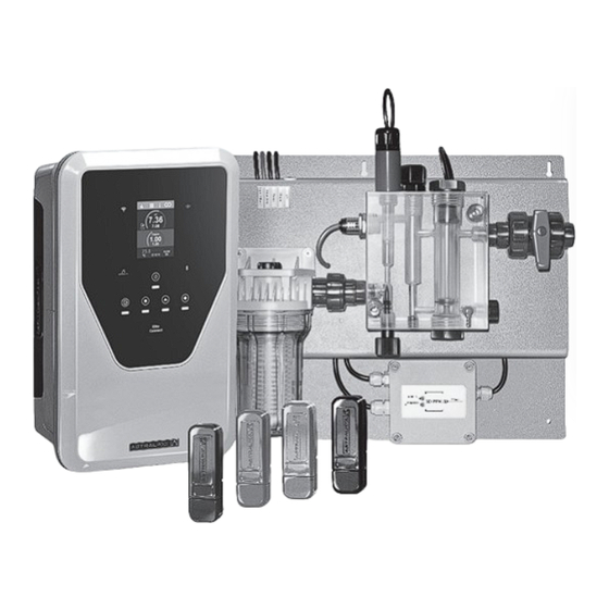
Page 28: Description
4 Description Power Supply MODEL Description PH/ORP_LINE PH/ORP_PRO PH/PPM_PRO Operating voltage 230 Vac 50/60 Hz. Consumption (W) 27 W PH/ORP PH/ORP PH/Cl (PPM) Parameters T (°C) T (°C) T (°C) pH: relay (NO, 0.5A max) Control output ORP, Cl2: relay (NO, 0.5A max) 4 x (potential-free max 24 V) Control inputs 4 potential-free (interlocks) -
Page 29: Dimensions
5 Dimensions Flow switch 1) Inlet 2) Pre-filter 3) Outlet ORP Probe holder Injection temperature sensor x 2 Flow switch PH/ORP_LINE PH/ORP_PRO PH/PPM_PRO 6 Installation Diagram 230 V PPM sensor Power supply pH sensor Inductive sensor (F.S.) Temperature sensor Electrical control panel pH pump Cl pump Filter... -
Page 30: Control Unit Installation
7 Control Unit Installation Wall-mounted control unit Wall plug: 8 x 50 mm Screw: 5 x 50 mm Always install the system’s control unit VERTICALLY and on a rigid surface (wall), as shown in the recommended installation diagram. To ensure that the equipment remains in good condition, it should always be installed in a dry, well-ventilated location. The equipment should not be installed outdoors The POWER SUPPLY should preferably be installed far enough away from the electrolysis cell to prevent it from being accidentally splashed with water. -
Page 31: Probe Holder Panels And Cell Installation
9 Probe Holder Panels and Cell Installation The probe holder panels and cell should be installed in a location protected from the weather and always downstream of the filtration system and any other devices in the installation such as heat pumps, control systems, etc. The installation should allow easy user access to elements of the probe holder panel and cell. -
Page 32: Power Supply And Panel Connections
10 Power Supply and Panel Connections Connections between probes and panels must be as shown in the following diagrams. Never alter their length or cross-section without first consulting your authorised distributor. CCONNECT PH/ORP_LINE CCONNECT PH/ORP_PRO CCONNECT PH/PPM_PRO FLOW SWITCH TEMPERATURE SENSOR INDUCTIVE INDUCTIVE... -
Page 33: Ph/Orp/Ppm Sensor Installation
11 pH/ORP/PPM Sensor Installation 1. Insert the pH/ORP/PPM sensor supplied with the equipment in the appropriate housing in the probe holder. 2. To do this, loosen the nut on the probe socket and insert the sensor. 3. The sensor should be inserted far enough to guarantee that the probe at its tip will always be submerged in the water flowing through the probe holder. -
Page 34: Removal
13 Removal Removing the power supply housing: 1. Remove the trim panel (A) from the front cover. 2. Unscrew the front cover fixing screws (B). 3. Pull off the front cover. 14 Initial Start-up 1. Ensure that the filter is 100% clean, and that the pool and installation is free of copper, iron and algae, and that any heating equipment installed is compatible with the presence of salt in the water. -
Page 35: Maintenance
15 Maintenance pH/ORP Sensor Maintenance (Maintenance 2–12 months). 1. Ensure that the sensor membrane is always damp. 2. If a sensor is not going to be used for an extended period of time, store it in a storage solution. 3. To clean a sensor, do not use abrasives that could score its surface. 4. - Page 36 If the sensor needs to be stored or transported, follow the procedure below: Procedure for storing the sensor and period of non-use: - The sensor must be stored correctly when the equipment is not being used or if the system will have no flow for more than 4 days. - Use a small screwdriver or similar tool to remove the transparent cover [13] protecting the bleed hole [12], and move it to one side so that the bleed hole [12] is accessible.
-
Page 37: Electronic Board
16 Electronic Board AUX 1 AUX 2 Input 230Vac AUX 1 pH PUMP HEAT AUX 2 <3V OUTPUT 4 X OUTPUT FREE POTENTIAL 4 X INPUT FREE POTENTIAL pump pump FREE (Loop max 24V 1A AC-DC) (Loop 0V) POTENTIAL >3V INTERLOCKS 3 X Output 230 Vac Use of relays with KIT4SAL... -
Page 38: Statistics Menu
17 Statistics Menu /Log /Log % + set V + I pH + set Techniques ClmV + set T (C) + g/L 7.35 7.30 % + set: Production log and established production set point disabled. ClmV pH + set: pH measurement and setpoint. 25.2 FLOW °C... -
Page 39: Configuration Menu
18 Configuration Menu /Config /Config /Config /Config /Config /Config Screen Date 31/08/22 MODBUS ADDR Electrolysis Biopool Timer1 (Aux1) Language Time 12:17 CAPACITIVE LOW SALT CONFIG Filtering Timer2 (Aux2) Sound MODBUS BAUDS 9600 FACTORY PROGRAMS UV CONFIG Backwashing Touch MODBUS PARITY Reset Config PAIRING CONFIG Boost Mode... - Page 40 Biopool: Increased range of pH and ClmV settings. pH: BIO OFF = 7.00–7.80 / BIO ON = 6.50–8.50 ClmV: BIO OFF = 600–850 / BIO ON = 300–850 /Config /Config /Config /Config Biopool Biopool 7.35 Screen Biopool Biopool Biopool 7.30 Language Filtering Filtering...
-
Page 41: Information Menu
Timer 1-2 (AUX 1-2): For configuring 2 additional auxiliary relays with associated timers (e.g. flocculant dosing pumps, lighting, BW, etc.). This function allows selection among manual, automatic, cycles and BW options. a) Manual b) Auto /Config /Timer1 (Aux1) /Config /Timer1 (Aux1) /Timer1 (Aux1) Auto Time Auto Time... -
Page 42: Relays Menu (Fluidra Pool)
20 Relays Menu (Fluidra Pool) Allows relay programs to be modified and interlocks to be set if necessary. 1. Relay selection. TUESDAY TUESDAY 2. Relay mode 6TH SEPTEMBER 6TH SEPTEMBER Week R1 Automatic mode (program) R1a R1a Thur R1a R1a R1a Relay on Week Relay off... - Page 43 Relay interlocking: 1) No interlocking. Config R1 TUESDAY 6TH SEPTEMBER 2) Digital interlocking selection (IN1, IN2, IN3, IN4). T(C) 3) Analog interlocking selection: temperature. T(C) Offset Time 4) Digital input status No interlocking. SAVE SAVE When the contact is open/closed, the relay will switch to ON.
-
Page 44: Ph Configuration
21 pH Configuration Clppm Sens Clppm Sens Clppm Sens Clppm Sens Clppm Sens /Config /Config /Config 7.60 7.60 Mode AUTO Hysteresis Reset Hours 7.25 PS 60m Intelligent pH+/pH- Reset Config INTEL 100% HYS 2s % Pump LEVEL FLOW OK Pump Stop pH INT pH: 6.5–8.5 LEVEL... - Page 45 Hysteresis: Time that the pump continues dosing when the measurement reaches the desired setpoint (Value cannot be changed). Intelligent: Smart pH- dosing function for more precise regulation. The working cycle of the pump is updated dynamically depending on the measurement. Clppm Sens /Config...
-
Page 46: Clmv/Clppm Configuration
22 ClmV/Clppm Configuration ClmV ClmV Sens ClmV Sens ClmV Sens ClmV Sens ClmV Sens /Config /Config /Config Clppm AUTO Hysteresis MODE Reset Config Intelligent OXD/RED 100% ClmV HIS 2m % Pump LEVEL FLOW OK Pump Stop Reset Hours 7.35 7.30 ClmV 7.30 ClmV/Clppm: Sets the setpoint value. - Page 47 Pump Stop: The ClmV/Clppm has a safety system (PUMP STOP FUNCTION) which acts ClmV Sens on the dosing pump and prevents the following: /Config Pump Stop AUTO MODE - Damage caused by dry running the pump (depleted Cl product). - Cl product overdose (damaged or old sensor). OXD/RED % Pump stop When the PUMP STOP FUNCTION is activated, the system stops the dosing pump after a...
-
Page 48: C Sensor Configuration
23 °C Sensor Configuration °C Clppm Sens Clppm Sens Clppm Sens Clppm Sens /Config /Config T (C/F) (F.E) FLOW OFF MAX/MIN T (C/F) Gas (F.E) Flow Switch (F.S) Flow Switch (F.S) MAX/MIN gr/L 27.2 27.2 m3/h Freeze-Prot T (c) T (c) Reset Config Heating g/L 3.0–8.0... -
Page 49: Sensor Calibration (Ph, Orp, Ppm, Temperature)
24 Sensor Calibration (pH, ORP , PPM, TEMPERATURE) Fast pH Calibration ‘Fast’ mode allows routine recalibration of the sensor when there are small errors in calibration with no need to remove the sensor or use calibration solutions. PROCEDURE: 1. Ensure that the sensor is immersed in water and that the filter system is running. 2. - Page 50 Standard ClmV Calibration (ORP) The controller’s calibration frequency must be individually determined in each application. However, we recommend this be done at least once a month while the swimming pool is in use. The ClmV has an automatic calibration system for ORP sensors based on the use of a 470 mV reference solution.
- Page 51 Calibration T(C/F) Temperature calibration makes it possible to adjust the value in the event of small deviations. PROCEDURE: 1. Use an external temperature sensor to measure the current value of the pool water. 2. Follow the procedure shown in the pictures below: Clppm Sens Clppm...
-
Page 52: Alarms
25 Alarms Text in grey =Option disabled White text = Option enabled gr/d Text in red = Alarms 25.3 Low/high pH alarm 4.10 PS 60 100% INTEL HYS 2s 25.1 Temperature alarm FLOW OK 35 h LOW pH 9.99 Gas (F.E) pH<6.0 Flow Switch (F.S) 7.10... -
Page 53: Low/High Temperature Sensor Alarm
25.1 Low/High TEMPERATURE Sensor Alarm - The temperature alarm will appear when the temperature values are out of range. 9.99 Gas (F.E) Flow Switch (F.S) 14.2 m3/h - When the water temperature is very low, the equipment will not reach 100% production T(C) due to low conductivity. -
Page 54: Ph - Flow Switch/Inductive Sensor Alarm
25.2 pH – Flow switch/inductive sensor alarm - The flow alarm will appear if there is no water flow (inductive or flow switch sensor). (F.E) 17.1 FLOW FLOW °C 12:15 Flow Switch (F.S) Inductive sensor Flow switch sensor 71537 CConnect-PH/ORP_line 71538 CConnect-PH/ORP_Pro 71539 CConnect-PH/ppm_Pro When the contact connected to this input is open (external flow... -
Page 55: Ph - High/Low Alarm
25.3 pH - High/low alarm - Low and high alarms appear if the reading is outside the set values. These values cannot 4.10 PS 60m 100% INTEL be modified. HYS 2s FLOW OK 35 h If the high pH alarm appears, the pH pump will be switched off according to the safety LOW pH pH<6.0 values set. -
Page 56: Ph - Check Pump
25.5 pH – CHECK PUMP -The pump check alarm is a visual warning to check the condition of the peristaltic pipe. 9.99 PS 60m INTEL 100% HYS 2s 7.10 - This alarm will appear every 500 hours (not configurable value) but will not affect the start/ FLOW OK 35 h stop of the pump. -
Page 57: Ph - Ph Fuse Alarm
25.7 pH – pH fuse alarm - This alarm will appear when the internal fuse of the board is blown. 9.99 PS 60m INTEL 100% HYS 2s 7.10 FLOW OK 35 h pH 6.0–9.0 Connecting the pH pump and FUSE checking the fuses pH peristaltic pump con-... -
Page 58: Basic Troubleshooting
26 Basic Troubleshooting Message Solution The flow alarm will appear if there is no water flow (paddle flow switch sensor). - Check the pump, filter and backwash valve. Clean if necessary. - Check the paddle flow switch sensor wiring connections. FLOW switch alarm (F.S) Low or high alarms appear if the reading is not within established safety limits. -
Page 59: Warranty
27 Warranty GENERAL CONSIDERATIONS - In accordance with these conditions, the seller guarantees that the product covered by this guarantee conforms to its specifications at the moment of its delivery. -The warranty period of the product is that which is determined by the legal requirements of the country in which the product was acquired by the consumer. - Page 60 SIMPLIFIED EU DECLARATION OF CONFORMITY I.D. Electroquímica S.L. hereby declares that Elite Connect R equipment complies with the 2014/53/EU and 2011/65/EU + 2015/863 Directives. The full text of the EU Declaration of Conformity is available at the following web address: (www.astralpool.com).
Need help?
Do you have a question about the Control Connect-PH/ORP line and is the answer not in the manual?
Questions and answers