Advertisement
Before using the device, check the device model and ensure that the shipped box includes the
following items:
1
R20A
1
Sealing pressing plate
1
Rubber plug (large)
Wall-mounting Accessories :
2
M4x30 crosshead screw
1
Allen wrench
1
Wiring cover
2
Diode
1
Wall-mounting bracket
4
Plastic wall anchor
Wall-mounting Installation
6
M2.5x6 crosshead screw
1
Rubber plug (small)
4
Wall-mounting screw
4
ST4x20 crosshead screw
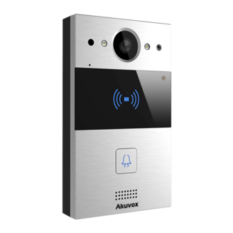
Infrared LED
Infrared Sensor
Camera
Microphone
Photosensitive Sensor
Card Reader
Call Button&Status LED
Speaker
R20A
1
Rope
1
Rubber plug (medium)
2
M3x6 hex socket screw
Advertisement
Table of Contents

Subscribe to Our Youtube Channel
Related Manuals for Akuvox R20A


Summary of Contents for Akuvox R20A
- Page 1 R20A Wall-mounting Installation Before using the device, check the device model and ensure that the shipped box includes the following items: Rope R20A Wiring cover M2.5x6 crosshead screw Diode Rubber plug (medium) Rubber plug (small) Sealing pressing plate Rubber plug (large)
-
Page 2: Wall Mounting Installation
R20A Wall-mounting Installation Before You Start Tools needed (not included in shipped box) Cat Ethernet Cable Crosshead Screwdriver Electric Drill Voltage and Current Specifications It is suggested that use PoE or 12VDC 1A power adapter to power on device. AWG Sizes and Properties Table... - Page 4 Inst Step1: Wall-mounting Bracket Installation 1. With an electrical junction box in the wall 1.1. With an 86x86 mm junction box Fix the wall-mounting bracket on the embedded box with two M4x30 crosshead screws. Mark two holes on the wall. Take down the two M4x30 crosshead screws and remove the wall-mounting bracket.
- Page 5 R20A Wall-mounting Installation Tighten the wall-mounting bracket and junction box on the wall with two ST4x20 crosshead screws and two M4x30 crosshead screws. Finish the wall-mounting bracket installation. 1.2. With a 2x3 inches junction box. Fix the wall-mounting bracket on the 2x3 inches junction box with two M4x30 crosshead screws.
- Page 6 R20A Wall-mounting Installation 2.Without an electrical junction box in the wall Mark four screw holes through the wall-mounting bracket on the wall. Use a 6 mm hand drill to drill the four holes with a depth of 25 mm. Insert four plastic wall anchors into the holes.
- Page 7 R20A Wall-mounting Installation Step 2: Main Unit Installation Hang R20A on the wall-mounting bracket with rope for easier installation. Make wires go through the wiring cover and connect them to the corresponding (for details, refer to "Wiring Interface"). Fasten the wiring cover with four M2.5x6 crosshead screws.
- Page 8 R20A Wall-mounting Installation Mark the two holes of the wall-mounting bracket on the wall. Select a suitable rubber plug to secure the wires. Fix sealing pressing plate to the wiring cover with two M2.5x6 crosshead screws. Insert the four wall-mounting screws on the device into the corresponding holes on the wall-mounting bracket.
-
Page 9: Device Test
R20A Device Test LED Status Description Normal status Always on Blue Calling Flashing Offline Flashing Talking on a call Always on Green Receiving a call Flashing Note: For more LED settings, please refer to R20A web: Intercom > LED Setting. -
Page 10: Warranty
1. Akuvox warranty does not cover intentional mechanical damage or destruction caused by improper installation. 2. Do not attempt to modify, alternate, maintain, or repair device by yourself. Akuvox warranty does not apply to damages caused by anyone who is not representative of Akuvox or an Akuvox authorized service provider. Please contact Akuvox Technical Team if the device need to be repaired.
Need help?
Do you have a question about the R20A and is the answer not in the manual?
Questions and answers