
Related Manuals for Dormakaba E-Plex 2000 Series


Summary of Contents for Dormakaba E-Plex 2000 Series
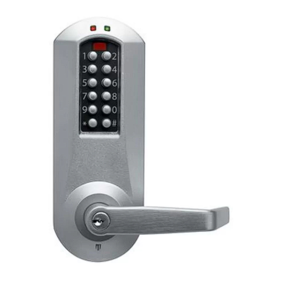
- Page 1 E-Plex 2000 Series PowerPlex 2000 Series Installation Instructions PKG3218 0723 Original document...
- Page 2 APPLICABLE FOR UNITED KINGDOM INSTALLATIONS ONLY It is the responsibility of the installer to ensure that the installation of this product complies with the relevant regulations applicable to the territory / country (UK only). • This lock was included in a successful fire test (EN 1634-1) on a timber door, which relied on the use of intumescent protection as detailed below.
-
Page 3: Table Of Contents
These instructions are designed for use by maintenance professionals or lock installers who are familiar with common safety practices and competent to perform the steps described. dormakaba is not responsible for dam-age or malfunction due to incorrect installation. Important: Carefully inspect windows, doorframe, door, etc. to ensure that the recommended procedures will not cause damage. -
Page 4: Cylindrical Installation
A. CYLINDRICAL CHECKLIST Parts and Tools List Each E-Plex/PowerPlex 2000 lockset includes: • Outside lock housing • Inside lock assembly • Outside lever • Gasket for outside lock housing (not for PowerPlex 2000 versions) • Cylindrical latch • Cylinder drive unit •... - Page 5 TOOLS REQUIRED: • Safety glasses • Phillips screwdriver (#2) • ⁄ ” (13 mm) chisel • Fine steel file • ⁄ ” (3 mm) drill bit • Router • ⁄ ” (13 mm) drill bit • Adjustable square • ⁄ ”...
- Page 6 A-1. Door Preparation Note: Drill from both sides of the door to prevent unsightly damage. 1. Determine which template fits your E-Plex 2000 installation (either the ⁄ ” [60 mm] Backset or the 2 ⁄ ” [70 mm] Backset). 2. Place appropriate paper template (supplied) onto door and mark for holes.
- Page 7 A-3. DOOR THICKNESS Depending on the kind of spacers shipped with the lock, choose Table 1 or Table 2 to prepare the attachment plate and cylindrical drive unit for door thickness different than 1 ⁄ ” assembled in the factory. Note: It is very important to assemble the spacers in the position shown.
- Page 8 2. LOCK WITH 2 DIFFERENT SPACERS The cylindrical unit and plate assembly is Correct Position of Spacers shipped assembled in factory for 1 ⁄ ” See Table 2 (44 mm) door thickness up to 1 ⁄ ” [46 mm] with 2 spacers “07”; 1 spacer “08” and 2 flat head screws ⁄...
- Page 9 A-4. INSTALLING LOCK HOUSINGS Square Spindle Position Remove the cylindrical plate assembly from the outside housing (a). Insert the slotted end of the square spindle into the outside housing lever hub until it locks, at an angle of 45º. correct incorrect (The spindle can be removed by pulling on it, if oriented incorrectly.)
- Page 10 (continued from previous page) Do the following before placing the inside trim assembly on the door: Install the additional tension spring (i) between the plate (j) and the post (p), on the side opposite the lever handle spring installed in the last step. Put the thumbturn (T) in a vertical position.
-
Page 11: Mortise Installation
B. MORTISE Checklist and Exploded Views (Mortise Only) Each E2000 Mortise lockset includes: Outside lever handle (or) Parts for Mechanical override model only: ) Outside lever handle ) Outside housing ) Cylinder plug ) Cylinder (for locks with KIL option) ) Cylinder cap ) Instruction sheet “How to attach lever on lock”... - Page 12 Tools Required: • Safety Glasses • 1/2” (13mm) chisel • 1/8” (3mm) drill bit • 1/2” (13mm) drill bit • 1” (25mm) drill bit or hole saw • Drill • Awl or center punch • Hammer Rubber mallet • Small flat screwdriver •...
- Page 13 American Standard Mortise illustrated American Standard Mortise illustrated...
- Page 14 B-1. Installation of Standard ASM Models 1. Check the Mortise Handing a. Compare the mortise with the diagram below. If the mortise is the correct handing for the door, continue with step 2. Note: Refer to B-2 to change the handing of a field-reversible mortise. Door Handing (Top View) Right Hand (RH) Left Hand (LH)
- Page 15 2. Install the Strike a. Align the paper template on the door frame at the desired handle height, and along the vertical center line of the mortise (CL), which is also the center line of the door edge, allowing for any bumpers on the door frame.
- Page 16 e. Remove material from within the strike outline so that the strike will be flush with the doorframes. f. For ASM, install the dust box (optional for wood door frames, required for metal door frames), and check the strike handing on the template. Install the strike using the screws provided.
- Page 17 B-2. Reversing the Mortise Handing 1. Reversible ASM a. Remove the mortise faceplate. Place the mortise on a flat surface for the following steps. b. Partially extend the deadbolt: For normal ASM, rotate hub (H) using a screwdriver, until the deadbolt (D) extends approximately 1/4”.
- Page 18 For Autodeadbolt ASM, rotate hub (H) until the deadbolt (D) is fully retracted. The deadbolt will extend approx. 1/16” from the mortise case. 1/16” Hold deadbolt (D) gently. Press and release the auxiliary latch (X). You should feel the deadbolt trigger and begin to extend under the force of the spring. D (hold gently) X (press and release) Release the deadbolt (D) gently.
- Page 19 1. Reversible ASM (continued) c. Push in the latch bolt (L) to the middle of its stroke, and hold it there. (Continue Step 1 and 2) Lock Position Unlock Position Push in the latchbolt to the Use a small screwdriver end of the stroke, and hold to lift unlock mechanism.
- Page 20 d. Pull out the latch bolt (L), until it just clears the front plate. (Note: If you remove the bolt completely, you must turn it 90° to re-insert it.) 180° 180° 180° Rotate the latch bolt (L) 180°. Re-insert it to the end of its stroke. Holding tool (S) in place, re-engage tailpiece (T) with latch bolt (L) (slide tailpiece down).
- Page 21 e. Release the latch bolt (L). Position the latch bolt so that the bottom tooth of the anti-friction latch (F) remains inside the mortise case as shown. Note: If the tooth of (F) is outside the mortise, you will not be able to re- assemble the faceplate on the mortise.
- Page 22 B-3. Additional steps for Autodeadbolt ASM inside trim assembly If not already installed at the factory, put the thumbturn in the vertical position and install all four (4) parts (M) as shown, on the inside trim assembly. RH/LHR LH/RHR RH/LHR LH/RHR Install clip M1 diagonally on hub...
- Page 23 If using the installation jig to prepare the door, refer to the side with the lower-beveled edge using the instructions provided with the jig, then proceed with step “L". Remove the template. and mark 6 below. 1. Mark the handle ( (CL) side with t 4.
- Page 24 “L". Remove the template. side with the lower-beveled edge using the dashed line marked “L". Remove the template. 4. Prepare the cut-outs for the mortise in the edge of the door using a mortising machine, router and chisel (for dimensions, 4.
- Page 25 Place 3 spacers (S) on the door (for recent models only). Place the inside trim assembly on the door so that the upper and lower spindles (F) and (G) engage the thumbturn and the inside lever. Fasten to the outside housing using the three 1/8” hex head mounting screws (I).
- Page 26 B-5. Install the Outside Housing and Inside Trim Assembly 3.4 Install the Outside Housing and Inside Trim Assembly for E-760/770/790 and 660 Without Ke for 2000 Series without Key Override (for E2000 (for E-760/660/770/790 with Mechanical Override, see page 16) Series Key Override, see Section F) (for E-760/660/770/790 with Mechanical Override, see page 16) A- For Mortise...
- Page 27 m Assembly for E-760/770/790 and 660 Without Key Override verride, see page 16) m Assembly for E-760/770/790 and 660 Without Key Override 5. On the inside trim assembly turn the lever to the correct horizontal rest erride, see page 16) 5.
- Page 28 8. Three AA batteries should already be installed in the battery holder (C). Insert the battery holder into the outside housing and secure it using the supplied 6-32 x 5/16” (7.9mm) Phillips screw (H). Note: If the lock makes a continuous buzzing noise or the red LED lights continuously, reset the electronics by removing the battery holder for ten seconds then reinsert it.
-
Page 29: Exit Trim Installation
C. EXIT TRIM C-1. CHECKLIST FOR PRECISION EXIT DEVICES 21/22/ FL21/FL22 VON DUPRIN 98/99EO-F/9827/9927 EO- F/9875/9975/9847/9947 ** DETEX 10/F10/20/F20 DORMA F9300 YALE 7100/7160/7170 Mechanical Override Models ONLY (Not for PowerPlex 2000 Versions) (Not for PowerPlex 2000 Versions) ** Detex 10 & 20 Series are Panic Hardware only. (Not fire rated) Detex F10 &... - Page 30 C-2. PREPARE THE DOOR FOR THE APPROPRIATE EXIT DEVICE Choose the drilling template of the lock for the exit device to be assembled on the door. 2. Mark the desired handle height on the edge of the door. (see Fig.1) 3.
- Page 31 Install the Mortise (if applicable) e exit devices, install the mortise according to acturer’s instructions. C-3. INSTALL THE LOCK AND EXIT DEVICE INS TA LL TH E L OC K AND T H E EX IT D EV ICE Install the Outside Lever Install the Mortise (if applicable) Install the Mortise (if applicable) For mortise exit devices, install the mortise according to the...
- Page 32 4. Install Lock & Exit Device on the door a. Choose the required SPINDLE BAG from the spindle chart in the Hardware bag depending ON THE TYPE OF EXIT DEVICE AND THE DOOR THICKNESS on the door on the door on the door b.
-
Page 33: Installing Outside Lever On Non-Mechanical Override
D. INSTALLING OUTSIDE LEVER ON NON-MECHANICAL OVERRIDE Assemble the lever on the outside housing in the hori- zontal rest position appropriate to the handing of the door. Simply push the lever onto the tube until it clicks in place. If more force is required, use a rubber mallet. Test the attachment of the handle by pulling on it to make sure it is securely fastened. -
Page 34: K-I-L Cylinder Adaptor Assembly Instructions
Medeco M3-Bi-Level 20J200V1-XXX Medeco Biaxial 20W200V1-XXX KIK CYLINDER ADAPTOR ASSEMBLY INSTRUCTIONS Medeco 3-BX-3 20T200V1 -XXX KIK CYLINDER ADAPTOR ASSEMBLY INSTRUCTION Medeco M3-Bilevel 8 20J200H1-XXX Medeco Keymark X4 20N200V1-XXX F. K-I-L CYLINDER ADAPTOR ASSEMBLY INSTRUCTIONS REMOVE SCREWS ITEM #2 REMOVE OLD ADAPTOR ITEM #3 REPLACE WITH ADAPTOR OPTION B ITEM #4 F-1 Adaptor A REPLACE SCREWS ITEM #2... -
Page 35: Installing Optional K-I-L Key Or Best Removable Core
G. INSTALLING OPTIONAL K-I-L KEY OR BEST REMOVABLE CORE OVERRIDE AND OUTSIDE LEVER G-1 Upon unpacking, the lock housing with mechanical override should look like the diagram below with: • The small indents (i) on the cross of the override shaft (m) in line horizontally (c, d) •... - Page 36 For Optional K-I-L Key G-8 Put the cylinder plug (k) into the lever (h). G-9 Making sure that the cylinder plug (k) does not fall out, insert the key into the cylinder (j). The key will be horizontal. Caution: The position of the key is very important. If the lever is not assembled with the key in the correct position before placing the lever on the housing, the inside mechanism of the lock could be damaged if the lever is rotated and forced.
-
Page 37: Testing The Operations Of The Outside Lever
Right-Handed lock G-13 Remove the key. The lock will look as shown at right. G-14 Gently check the rotation of the lever handle. It should easily rotate approximately 45º. Troubleshooting: If you have assembled the lever and housing with the key in the wrong position, the key will get stuck. -
Page 38: Testing The Mechanical Key Override With Change Key
H-2 Test the Movement of the Lever (without the key in cylinder) a. Turn the lever (h) clockwise for a Right-Handed lock or counter-clockwise for a Left-Handed lock b. Release the lever slowly. It should return freely to its horizontal position. I. -
Page 39: Changing Lock Cylinders
Install cap (i) to cover key hole. The cap has a small Top snap groove on one edge (to allow ease of removal). This (Second) should be facing down. Insert bottom snap of cap in lever hole below the cylinder. With a small screw- driver, push top snap of cap down while pushing the Bottom snap i (First) -
Page 40: Changing Best-Type Core
K. CHANGING BEST-TYPE CORE Use the control key to remove the removable core from the lever K-2 Remove the adapter from the removable core and reassemble it on the new removable core. Note: It is important that the new removable core has the same number of pins (6 or 7) as the dismounted one. -
Page 41: Installing Rubber Bumpers
M. INSTALLING RUBBER BUMPERS M-1 Close the door and apply pressure making sure the deadlatch (a) rests on the strike plate (b) as shown. Standing on the frame (door stop) side of the door, check for gaps between the door and the frame on the three sides of the frame (left, right, and top). -
Page 42: Testing The Operation Of The Lock
O. TESTING THE OPERATION OF THE LOCK O-1 Rotate inside lever and hold. Ensure that the latch is fully retracted and flush with the latch faceplate. Release the inside lever; the latch should be fully extended. O-2 For PowerPlex 2000 you need to activate the outside lever 3 to 4 times to power the lock prior O-3 Enter the factory-set combination: 1,2,3,4,5,6,7,8. - Page 43 Notes...
- Page 44 Notes...
- Page 45 Notes...
- Page 46 Door Electronic Hardware Access & Data Mechanical Lodging Key Systems Systems Entrance Interior Glass Systems Systems Safe Service Locks dormakaba USA dormakaba Customer Services & Support Phone: 800.849.8324 General Info: www.dormakaba.com dormakaba.com PKG3218 0723...
Need help?
Do you have a question about the E-Plex 2000 Series and is the answer not in the manual?
Questions and answers