Advertisement
dormakaba
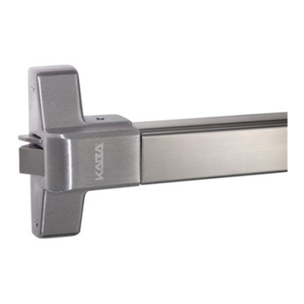
ED22
ED22 Rim Exit Device
Installation Instruction - Reversible (Non Handed)
01
Door Preparation
Draw the center line of the device across the door and frame at
40 5/16" (1024) above the floor.
A.
If door has preparation for 2 3/4" (70) backset cylindrical
lock, mount panic strike using center of 2 1/8" (54) diameter
lock hole.
B.
If your door has cylindrical lock cut-out for ANSI A115.2 and
A115.3 prep doors:
B1. Extend horizontal and vertical center lines of cut-out
shown at right.
B2. If frame has 5/8" (16) stop, align center lines on template
with center lines on door. Drill template holes as
described above and follow steps three thru seven.
B3. If frame has 1/2" (12.7) stop, align center lines on
template with center lines on door and spot mounting
holes for latch assembly only. Then move template up
against stop and spot mounting holes for strike. Drill two
mounting holes. Now follow steps three thru six.
Note special shim shown at right, which is mounted
beneath strike.
Screw
*Machine
Diameter
Screws
All Door
24 GA
Gauges
#8
#29 (3.5)
1/8" (3.2)
#12
#16 (4.5)
#19 (4.2)
*Machine screws are intended for use with doors having
sufficent metal thickness for proper tapping (reinforced doors)
or sex bolts.
Item
Q'ty
Front plate assembly and
4
rear bracket
Strike
2
Edge Filler
4
Strike Filler
4
Drill sizes for screws are recommended but various factors, such
as type of door and frame construction, thickness and type of
metal, etc, can affect the final hole diameter and resulting
holding strength of the fastener.
1
Twist Drill Sizes
Self Tapping Screws
20 GA
18 GA
16 GA
1/8" (3.2)
#30 (3.3)
#29 (3.5)
#19 (4.2)
#18 (4.3)
#16 (4.5)
Screw Chart
Fastener
#12 x 1 1/4" Lg. pan head tapping
screws type "A"
#12 x 1 1/4" Lg. pan head tapping
screws type "A"
2 #8-32 x 1/2" machine screw,
2 #8 x 1" pan head tapping scew
2 #12-24 x 1/2" flat hd. machine screw,
2 #12 x 3/4" pan hd tapping scew
02
Lock and Drill template Holes:
Locate and drill mounting holes for trim, device and strike using
furnished template.
Dim Inside ( ) are in mm
Advertisement
Table of Contents

Related Manuals for Dormakaba ED22


Summary of Contents for Dormakaba ED22
- Page 1 ED22 ED22 Rim Exit Device Installation Instruction - Reversible (Non Handed) Door Preparation Draw the center line of the device across the door and frame at 40 5/16” (1024) above the floor. If door has preparation for 2 3/4” (70) backset cylindrical lock, mount panic strike using center of 2 1/8”...
- Page 2 ALWAYS refer to the Trim Installation template packed with trim Cut off length of cylinder connecting bar so that 1/2” (12.7) before proceeding with projects beyond inside of door. installation. Dim Inside ( ) are in mm CAUTION When using the Ansi Cylinder plate, be sure the bosses on the latch assembly fit into the cutouts on the cylinder plate so that the latch assembly lies flat on the door.
- Page 3 ED22 Bar Length Adjustments Calculate the length to be cut (A). *RL (Required length) = Door width minus 4” (101.6) Remove the rear cover and rear mounting bracket. **A = Length of device- Required length (RL) Depress push bar and cut off to desired length.
- Page 4 How to Test Push Bar and Dogging Device Latch bolt is retracted by the push bar inside. Latch bolt is retracted by the push bar inside and the key outside. Turning the key in either direction will retract the latch. Return ket to the horizontal position to remove key and project latch, Latch bolt is retracted by the push bar inside and the key or knob outside.
Need help?
Do you have a question about the ED22 and is the answer not in the manual?
Questions and answers