Table of Contents
Advertisement
Contents
1
About this document
2
3
4
5
6
7
8
9
10
11
1
About this document
1.1
Contents and purpose
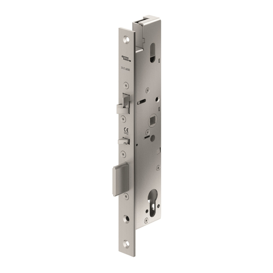
SVP/SVZ door locks are available in various designs
for tubular frame doors and for solid doors. This
manual describes mounting in tubular frame and solid
doors.
1.2
Target group
SVP/SVZ door locks must only be mounted by
technically qualified personnel.
1.3
Other applicable documents
• Manual for the connection cable SVP-A 1100/2100
(not necessary for SVP 5000)
• Mounting instructions for the components used, e.g.
the door handle
1.4
Abbreviations
Emergency lock with self locking
SVP
action
Access control lock with
SVZ
self locking action, without
emergency escape action
2000, 2000F,
All versions of a door lock; the
4000, 5000,
exact lock type is marked with 3
6000
digits instead of zeros.
Software for the dormakaba
TMS Soft®
door management system (TMS)
SVP/SVZ door locks
Mounting instructions
DCW® is the short form for
1
"DORMA Connect & Work".
2
A dormakaba-owned fieldbus
3
system for the connection of up
8
to 4 identical components to a
15
DCW® central unit.
18
Serial fieldbus system according
18
to ISO 11898-3, for connecting
19
several components to one cable
20
harness
20
RR
Tubular frame locks
20
VB
Solid door locks
1.5
Symbols used
1.5.1
Hazard categories
WARNING
This signal word indicates a possible
hazardous situation which may result in
death or serious injury if not averted.
ATTENTION
This signal word indicates a situation of
potential risk, which could lead to damage
to property or the environment if not
averted.
TIPS AND RECOMMENDATIONS
This signal word indicates useful information
for efficient and trouble-free operation.
1.5.2
More symbols
1.
2.
Sequence of action steps
Item numbers used in image
1
2
caption
WN 059744 45532/14767
2020-03
EN
Advertisement
Table of Contents


Need help?
Do you have a question about the SVP and is the answer not in the manual?
Questions and answers