Advertisement
Quick Links
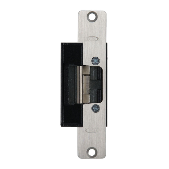
INSTALLATION
RCI 6 SERIES
ELECTRIC STRIKES
Instructions
The RCI L65 Low Profile version accepts 1/2" or 5/8" latch
projection (perfect for narrow stile aluminum frames). The
RCI S65 Standard version is ideal when you require 3/4"
latch projection.
1. Determine the vertical centerline of the door lock face
and the horizontal centerline of the latch.
IMPORTANT: When determining the horizontal
centerline observe the following:
FOR MORTISE LOCKS: Align the angled ramps of the lip
bracket with the deadlock trigger of the mortise latch.
FOR CYLINDRICAL LOCKS: Align the center of the latch
with the center of the strike opening.**
2. Transfer both the horizontal and vertical centerlines to
the doorframe.**
3. Prepare the doorframe for cutting as shown in the
appropriate drawing.
RCI S6504 Aluminum Frames, 1-3/16" Insert Depth
Modular AS65 with B604 faceplate
A
1-1/4
1.250
31.75
B
4-7/8
4.875
123.83
C 3-3/8
3.375
85.73
D 1-3/16
1.188
30.16
E
3/8
.375
9.53
F
1/8*
.125*
3.18*
G 1-11/16
1.688
42.86
Vertical Vertical Vertical
Vertical Centerline
X
C/L
C/L
C/L
of Door**
Door
Door
Door
R
5/32
0.156
3.97
K
4-1/8
4.125
104.78
M 12-24
—
—
NOTE: Specifications subject to change without notice.
* Dimension F is measured from face of mounting tab to face of frame.
** Dimension X on the drawing is determined by the vertical centerline of the door. If the latch incorporates a deadlocking pin additional steps
will be necessary to ensure proper operation of the deadlocking pin. Measure the thickness of the deadlocking pin and add this thickness
to Dimension X to relocate the vertical centerline an appropriate distance on the frame.
IS6A-(B)
C L
X
M
R
E
D
G
C L
F
M
K
C
B
G
A
© 2019 dormakaba Canada Inc
www.dormakaba.us • Phone: 1.800.265.6630 • Fax: 1.800.482.9795 • E-mail: sales_RCI@dormakaba.com
UL 294 Performance Ratings:
Access Control Line Security : Level I
Destructive Attack : Level I
Endurance : Level IV
Standby Power : Level I
4. If required, install the 'no weld' mounting brackets per
page 4.
5. Attach the strike faceplate to the lip bracket with the
self-tapping screws provided. (It may be desirable to
leave these screws slightly loose to facilitate insertion
into the doorframe.
6. Connect the incoming wiring from the power supply
(see wiring instructions).
7. Install the door strike in the doorframe using the
screws provided.
RCI L6504 Aluminum Frames, 1-1/16" Insert Depth
Modular AL65 with B604 faceplate
A
1-1/4
1.250
31.75
B
4-7/8
4.875
123.83
C 3-3/8
3.375
85.73
D 1-3/32
1.094
27.78
E
3/8
.375
9.53
F
1/8*
.125*
3.18*
G 1-11/16
1.688
42.86
Vertical Vertical Vertical
Vertical Centerline
X
C/L
C/L
C/L
of Door**
Door
Door
Door
R
5/32
0.156
3.97
K
4-1/8
4.125
104.78
M 12-24
—
—
C L
X
M
R
E
D
G
C L
F
M
K
C
B
G
A
R07-19GR-1
PCN18043
Advertisement

Related Manuals for Dormakaba RCI 6 Series


Summary of Contents for Dormakaba RCI 6 Series
- Page 1 Measure the thickness of the deadlocking pin and add this thickness to Dimension X to relocate the vertical centerline an appropriate distance on the frame. © 2019 dormakaba Canada Inc PCN18043 IS6A-(B) www.dormakaba.us • Phone: 1.800.265.6630 • Fax: 1.800.482.9795 • E-mail: sales_RCI@dormakaba.com R07-19GR-1...
- Page 2 Dimension X to relocate the vertical centerline an appropriate distance on the frame. For wood frame door installations, substitute #12 wood screws for dimension M. † © 2019 dormakaba Canada Inc www.dormakaba.us • Phone: 1.800.265.6630 • Fax: 1.800.482.9795 • E-mail: sales_RCI@dormakaba.com...
- Page 3 Dimension X to relocate the vertical centerline an appropriate distance on the frame. For wood frame door installations, substitute #12 wood screws for dimension M. † © 2019 dormakaba Canada Inc www.dormakaba.us • Phone: 1.800.265.6630 • Fax: 1.800.482.9795 • E-mail: sales_RCI@dormakaba.com...
- Page 4 4. For a tighter fit, pre-bend the two long flange tabs before sliding onto the frame where space allows. 5. Secure the strike to the frame as per strike installation instructions. © 2019 dormakaba Canada Inc www.dormakaba.us • Phone: 1.800.265.6630 • Fax: 1.800.482.9795 • E-mail: sales_RCI@dormakaba.com...
-
Page 5: Wiring Instructions
Strike Insert Lip Bracket NOTE: Contacts are indicated with the keeper in a closed Fig. 3 Lip bracket adjustment and locked condition, with no latch present. © 2019 dormakaba Canada Inc www.dormakaba.us • Phone: 1.800.265.6630 • Fax: 1.800.482.9795 • E-mail: sales_RCI@dormakaba.com... - Page 6 Latch or keeper are not Confirm that the keeper is closing properly and that the functioning properly lever in the strike cavity is operating freely. © 2019 dormakaba Canada Inc www.dormakaba.us • Phone: 1.800.265.6630 • Fax: 1.800.482.9795 • E-mail: sales_RCI@dormakaba.com...
Need help?
Do you have a question about the RCI 6 Series and is the answer not in the manual?
Questions and answers