
Related Manuals for Landoll Brillion WFP23-37


Summary of Contents for Landoll Brillion WFP23-37
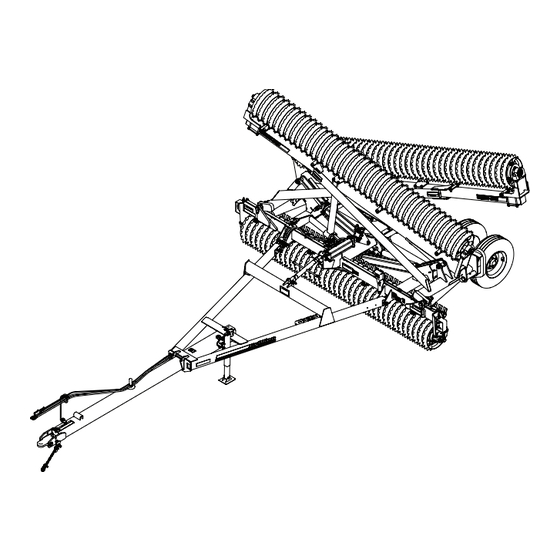
- Page 1 ‘ Wing Float Pulverizer Models WFP23-37 Operator’s Manual LANDOLL COMPANY, LLC 1900 North Street Marysville, Kansas 66508 (785) 562-5381 800-428-5655 ~ WWW.LANDOLL.COM F-1108-2406...
- Page 2 Manuals for Wing Float Pulverizers 23-37 Manual Number Manual Type F-1108 Operator’s Manual F-1109 Parts Manual...
- Page 3 Table of Contents Safety Information Introduction ........... . 1-1 Description of Unit .
- Page 4 TABLE OF CONTENTS Hydraulic Top Link Kit – Optional ........2-32 Float Lock Kit - Optional .
-
Page 5: Safety Information
Failure to comply with this warning can result in within 10 days of retail purchase, using the Landoll personal injury or death, damage to the implement Company, LLC Ag Products on-line registration process. -
Page 6: Understanding Safety Statements
TABLE OF CONTENTS Safety • When applying decals to the implement, be sure to clean the surface to remove any dirt or residue. Where possible, sign placement should protect the NOTE sign from abrasion, damage, or obstruction from mud, Investigation has shown that nearly 1/3 of all farm dirt, oil etc. -
Page 7: Maintenance Safety
TABLE OF CONTENTS Safety Instructions for Towing Maintenance Safety Vehicles • Block the machine so it will not roll when working on or under it. The maximum travel speed is the lesser of • Transport Locks installed. • The limit of the road conditions; •... -
Page 8: High Pressure Fluid Safety
TABLE OF CONTENTS High Pressure Fluid Safety Bolt, Escaping fluid under pressure can be nearly invisible and Hitch Lock Tractor 1-8 x 2-1/2 have enough force to penetrate the skin causing serious Drawbar injury. Use a piece of cardboard, rather than hands, to search for suspected leaks. - Page 9 SERIOUS PERSONAL INJURY. SEE OPERATORS MANUAL FOR CORRECT PROCEDURE. ITEM 4 - 3J675 ITEM 3 - 3J678 MEMBER DANGER LANDOLL COMPANY, LLC 1900 North Street WATCH FOR ELECTRICAL WIRES AND Marysville, Kansas 66508 OTHER OVERHEAD OBSTRUCTIONS WHEN FOLDING WINGS. FARM EQUIPMENT...
- Page 10 TABLE OF CONTENTS Figure 1-5: Drawbar Decals (2 of 5) F-1108-2406...
- Page 11 TABLE OF CONTENTS Front View Back View Figure 1-6: Center Frame Decals (3 of 5) F-1108-2406...
- Page 12 TABLE OF CONTENTS Figure 1-7: LH Wing Decals (4 of 5) F-1108-2406...
- Page 13 TABLE OF CONTENTS Wing - Right Hand Figure 1-8: RH Wing Decals (5 of 5) F-1108-2406...
- Page 14 TABLE OF CONTENTS Table provided for general use. NOTES: 1-10 F-1108-2406...
- Page 15 Chapter 2 TABLE OF CONTENTS Assembly IMPORTANT CAUTION All harnesses must be firmly attached to machine Do not work on or under this machine unless frame members, so they don’t sag or become torn securely blocked and supported by a hoist or loose by field debris.
- Page 16 TABLE OF CONTENTS Table provided for general use. NOTES: F-1108-2406...
- Page 17 TABLE OF CONTENTS Transport Axle Installation 4. Install the base end of the 4 x 16 Hydraulic Cylinder between the front lugs with a 1 x 5-1/2 Pin, Flat Washers, and 5/16 x 2 Roll Pins. The rod end of the NOTE Cylinder will be attached to the Lift Linkage at the The Bearing Inserts are maintenance free and require no...
- Page 18 TABLE OF CONTENTS Transport Axle Linkage Installation NOTE Linkage must be free to rotate after assembly IMPORTANT The Transport Lock 1/2 x 6 Clevis Pin must be removed when lowering machine. 1. Assemble the Toggle Link Weldment to the Transport Axle Assembly with 1 x 6-3/4 Pin.
- Page 19 TABLE OF CONTENTS Hydraulic Cylinder 4 x 16 FRONT Roll Pin,3/8 x 2 Pin,1" w/Keeper Bolt,5/16-18 x 3/4 Spacer, 1-3/8 X 1-1/16 Link, Toggle w/Tap Rod Clevis Toggle Link Roll Pin,3/8 x 2 Pin,1 x 6-3/4 Flat Washer,1" Bolt,5/8-11 x 6 Clevis Pin,1/2 x 6 Must be removed when Spacer,...
- Page 20 TABLE OF CONTENTS Tire and Wheel Installation IMPORTANT Torque will drop after the first 10 hours of operation. WARNING Check the Wheel Bolt for proper torque after this interval and re-tighten them. Use a torque wrench to assure proper torque. Insufficient torque can cause stud breakage and damage the wheel pilots.
- Page 21 TABLE OF CONTENTS Center Frame Roller Installation Rotation Arrow must follow the direction NOTE of travel Wheel Stop is on the Clamp side of the Roller Assembly NOTE Crowfoot Wheel Rotation Arrow must follow the direction of travel. See Figure 2-5. Roller Assemblies are pre-assembled from the factory with trunnion bearings, shims, and retaining washers.
- Page 22 TABLE OF CONTENTS Center Frame Center Frame Bearing Hanger Bearing Hanger 3/4-10 Bolt Flat Top Washer Flat Top Washer Loosen 1-8 Bolt Trunnion Shim Stub Shaft Stub Shaft Bearing Washers Mount Center Frame Center Frame Bearing Hanger Bearing Hanger Flat Top Flat Top Washer Washer...
- Page 23 TABLE OF CONTENTS Roller Assembly Bolt,3/4-10 x 2-1/4 Shim Washers Lock Washer,3/4 Trunnion Washer Shim Washer Trunnion Mount Flat Top Washer Lock Washer,1" Trunnion Bearing Bolt,1-8 x 2-1/4 Washer,3/8" Thick Figure 2-7: Center Frame Roller Installation F-1108-2406...
-
Page 24: Drawbar Installation
TABLE OF CONTENTS Drawbar Installation 1. Attach Drawbar to Center Frame with 1 x 8 Pin. Place a 1" Flat Washers on each side of pin. Secure with 5/16 x 2 Roll Pin and Klik Pin. 2. Attach Turnbuckle to Center Frame and Drawbar with 1 x 5-1/2 Pin. - Page 25 TABLE OF CONTENTS Drawbar Jack, Hose Support 2. Attach the Hose Support to the Drawbar with 5/8-11 x 2 1/4 Bolt, 5/8 x 2 x 3/8 Washer and Flanged Locknut. and Manual Storage Canister 3. Install the Manual Storage Canister to the Drawbar Installation Mount with Hose Clamp.
- Page 26 TABLE OF CONTENTS Table provided for general use. NOTES: 2-12 F-1108-2406...
-
Page 27: Wing Fold Cylinder Installation
TABLE OF CONTENTS Wing Fold Cylinder 3. RH Cylinder ports are front facing and LH Cylinder ports are rear facing. See Figure 2-10. Attach base Installation end of the 4 x 36 Hydraulic Cylinder (WFP23-29) or 4-1/2 x 36 Hydraulic Cylinder (WFP31-37) to the Center Frame Ball Joints with the vendor supplied NOTE hardware. -
Page 28: Hydraulic Installation
TABLE OF CONTENTS Hydraulic Installation Plumb the Hydraulic Circuit CAUTION IMPORTANT Unfold and lower the unit to the ground and relieve Restrictors are installed in both the rod and base system pressure before attempting to repair, adjust, end of wing fold cylinders to prevent or disconnect components. - Page 29 TABLE OF CONTENTS 5. Install all the other Hydraulic Fittings into the Manifold. NOTE See Figure 2-15. The Magnet Hose Holder is used to prevent hoses from 6. Install Restrictors into the fold Cylinder ports and dragging when the Drawbar is extended. install an Elbow Fittings onto the Restrictors.
- Page 30 TABLE OF CONTENTS Figure 2-14: Hydraulic Layout 2-16 F-1108-2406...
- Page 31 TABLE OF CONTENTS Figure 2-15: Hydraulic Schematic F-1108-2406 2-17...
-
Page 32: Purging The Hydraulic System
TABLE OF CONTENTS Purging the Hydraulic System DANGER DANGER IMPORTANT Falling wings can cause injury or death. Stand Unfold and lower the unit to the ground and relieve clear when wings are being raised or lowered. system pressure before attempting to repair, adjust, or disconnect components. - Page 33 TABLE OF CONTENTS Table provided for general use. NOTES: F-1108-2406 2-19...
-
Page 34: Wing Installation
TABLE OF CONTENTS Wing Installation 1. Assemble the Wings onto the Center Frame. See Figure 2-17. At the rear of the Center Frame, slide the RH or LH Wing Guide Roller into the Center Frame Yoke/Guide. At the front of the Center Frame, place a Spacer on each side of the Spherical Bearing, positioning it between the Center Frame Lugs. - Page 35 TABLE OF CONTENTS Figure 2-17: Wing Installation F-1108-2406 2-21...
- Page 36 TABLE OF CONTENTS Wing Frame Roller Installation Rotation Arrow must follow the direction NOTE of travel Wheel Stop is on the Clamp side of the Roller Assembly. NOTE Roller Axle Assembly clamped end must be on the outer extremity of the Wing. NOTE Crowfoot Wheel Rotation Arrow must follow the direction of travel.
- Page 37 TABLE OF CONTENTS Bearing Hanger Clamp Flange Locknut, 5/8-11 Bolt,5/8-11 x 7 Bolt,3/4-10 x 2-1/4 Wing Assembly Washer,3/4 Bearing Hanger Trunnion Mount Trunnion Washer Wing Assembly Bolt,3/4-10 x 2-1/4 Lock Washer, 3/4 FRONT Trunnion Mount Roller Assembly Trunnion Washer Trunnion Mount Trunnion Bearing Figure 2-19: Wing Frame Roller Installation F-1108-2406...
- Page 38 TABLE OF CONTENTS Wing Rest Installation, 2. Install the LH Wing Rest LH to the LH Wing Frame 4-bolt Plate located on the side of the Wing Frame. WFP23-29 Secure with 1/2-13 x 2 Bolts, Flat Washers and Flange Locknuts. 1.
- Page 39 TABLE OF CONTENTS Wing Rest Installation, 2. Attach the Wing Rest Bumper Pads onto the top of the RH and LH Wing Rest with 3/8-16 x 1-1/2 Flat Head WFP31-37 Screws and Locknuts. 1. Install the RH and LH Wing Rest to the RH and LH Wing Frame 4-Hole Plate located under the Wing Frame Tube.
- Page 40 TABLE OF CONTENTS Warning Lamp Installation IMPORTANT All Harnesses must be firmly attached to machine NOTE frame members or Hydraulic Hoses so they do not sag or become torn loose by field debris. Use the tie Be sure when assembling Lamps onto Brackets that the wraps provided.
- Page 41 TABLE OF CONTENTS Figure 2-22: Electrical Layout F-1108-2406 2-27...
- Page 42 TABLE OF CONTENTS Center Roller Scrapers - 3. Install a Scraper at each end and at the center of the Scraper Tube with 3/8-16 U-Bolts and Flanged Optional Locknuts. Adjust the Scrapers so that they are centered between the Notched Wheels and adjust the Scrapers so that there is a 1/4"...
- Page 43 TABLE OF CONTENTS Wing Roller Scrapers - Optional With the Wing Rollers on level ground, install the Scrapers in the same manner that the Center Roller Scrapers were installed. See Page 2-28 and Figure 2-24. The Scrapers must be centered between the Notched Wheels along with a 1/4"...
- Page 44 TABLE OF CONTENTS Acre Meter Installation - 4. Adjust the Acre Meter Switch so the center line of magnet wheel and pickup switch are horizontally and Optional vertically aligned with a maximum 1/8" between Magnet Wheel and Pick-Up Switch. Now firmly tighten all screws.
- Page 45 TABLE OF CONTENTS Figure 2-26: Acre Meter Installation - Optional F-1108-2406 2-31...
- Page 46 TABLE OF CONTENTS Hydraulic Top Link Kit – 6. Install Adapters into the end of the Hoses and Male Couplers onto the Adapters. Optional 7. Secure hoses to the Drawbar with Tie Wraps. 8. Purge the Hydraulic Top Link Circuit. The hydraulic IMPORTANT system is not filled with oil and should be purged of air before transporting and field operations.
- Page 47 TABLE OF CONTENTS Elbow Restrictor,1/16 Hyd Cyl, 4 x 12 116493 w/Trunnion End Hose Asm, 3/8 x 312 164309 Hose Asm, Hyd Cyl, 3/8 x 300 4 x 12 w/Trunnion End Bolt On Lug Elbow Restrictor,1/16 Bolt On Lug U-Bolt,3/4-10 Locknut, 3/4-10 U-Bolt,...
- Page 48 TABLE OF CONTENTS Float Lock Kit - Optional Float Lock Kits prevents the Wings from floating which allows for the weight to transfer in softer field conditions. 1. Place Wing Float Stops into the Center Frame Yoke/Guide. See Figure 2-29. 2.
-
Page 49: Operation
Chapter 3 TABLE OF CONTENTS Operation DANGER DANGER DANGER DANGER Never allow anyone to ride on the Pulverizer at Always lock the tractor drawbar in the center any time. Allowing a person to ride on the position when transporting the unit. Failure to do machine can inflict serious personal injury or so can result in serious injury or death and cause death to that person. -
Page 50: Tractor Preparation
TABLE OF CONTENTS Tractor Preparation 6. Connect the 7-Pin Connector to tractor outlet, routing cable by avoiding pinch points. The Pulverizer is designed to be pulled by a tractor • Make sure the tractor has a good clean equipped with or without a hammer strap. See Figure 1-2. receptacle, free of dirt and corrosion. - Page 51 TABLE OF CONTENTS Hitch Lock The Hitch Lock prevents the hitch from moving in either the Spade or Clevis position. Note the different orientation of the Hitch Lock. • Spade position: Insert the Hitch Lock into the clevis end opening. Secure the Hitch Lock with 1 x 9-1/4 Pin and 1/4 x 1-1/4 Lynch Pin.
- Page 52 TABLE OF CONTENTS Telescoping Drawbar The Telescoping Drawbar is design to be operated with the Drawbar Extension retracted or extended. The Drawbar must be extended when used as a companion equipment. Pin Retracted Position Position accordingly as drawbar is being extended or retracted Pin Extended Position...
-
Page 53: Hydraulic System
TABLE OF CONTENTS Hydraulic System DANGER DANGER Falling wings can cause injury or death. Stand IMPORTANT clear when wings are being raised or lowered. Unfold and lower the unit to the ground and relieve system pressure before attempting to repair, adjust, or disconnect components. -
Page 54: General Operation
TABLE OF CONTENTS General Operation 3. Wings should always unfold first, then machine lowers. If not, reduce hydraulic fluid flow. 1. Horsepower requirements will vary due to speed, 4. With machine unfolded and lowered on a level moisture, residue and types of soils. Local dealers surface, adjust the Turnbuckle so the that each Wing can help in making recommendations for your Roller is at the lower 1/3 of its respective Guide Slot. -
Page 55: Transport Lock
TABLE OF CONTENTS Transport Lock Hair Pin Toggle Cotter Toggle Link Road to Field Link Weldment 1. Raise the machine fully. Wings should be folded. 2. Remove Hair Pin Cotter and 1/2 x 6 Clevis Pin that is used to lock the Toggle Links in the raised position. See Figure 3-6. -
Page 56: Scraper Adjustment
TABLE OF CONTENTS Scraper Adjustment 1. Unfold and Lower Pulverizer on a level surface. 2. Push Notched Wheels against welded Roller Axle End Stops. Add Clamp End Spacers if needed. See NOTE "Clamp End Spacers - Optional" on page 4-8. Notched Roller Wheel Scrapers are optional and 3. - Page 57 TABLE OF CONTENTS Loup Acre Meter Kit - Total Acres Optional Press the /FUNC button until the “TOTAL” LED is lit. The digits indicate the acres covered since the total acre counter was cleared. IMPORTANT To clear the total acre count, press and hold the UP and Acre Meter is dust and splash resistant, under no DOWN buttons for two seconds.
- Page 58 TABLE OF CONTENTS Battery Replacement If the display shows “Ent”: You must enter your password using the UP and DOWN buttons. When your The battery operated acre counter uses 3 AA batteries. password is displayed, press the /FUNC button to test The “BATT”...
-
Page 59: Transporting On A Trailer
TABLE OF CONTENTS Transporting on a Trailer 3. Disconnect Drawbar from tractor. 4. Retract Telescoping Drawbar if equipped. Rigid and Telescoping Drawbars can be removed when 5. Disconnect (Quick Coupling) Hydraulic Hoses and transporting the Wing Float Pulverizer on a trailer. the Ag Harness where the frame connects to the 1. - Page 60 TABLE OF CONTENTS Transport 6. Before transporting: • Know the transport height and width of the unit 1. Check and follow all federal, state, and local before transport. Use caution when transporting requirements before transporting the Pulverizer. near bridges and power lines. 2.
-
Page 61: Maintenance
Chapter 4 TABLE OF CONTENTS Maintenance General Torque Specifications (rev. 4/97) This chart provides tightening torques for general purpose applications when special torques are not specified on process or drawing. Assembly torques apply to plated nuts and capscrews assembled without supplemental lubrication (as received condition). They do not apply if special graphite moly-disulfide or other extreme pressure lubricants are used. -
Page 62: Hydraulic Fitting Torque Specifications
TABLE OF CONTENTS Hydraulic Fitting Torque Specifications 37 degree JIC, ORS, & ORB (REV. 10/97 This chart provides tightening torques for general purpose applications when special torques are not specified on process or drawing. Assembly torques apply to plated nuts and capscrews assembled without supplemental lubrication (as received condition). They do not apply if special graphite moly-disulfide or other extreme pressure lubricants are used. - Page 63 TABLE OF CONTENTS Fasteners Wheel Hub Bearing Maintenance Before operating your Brillion machine, check all hardware for tightness. Use the Tightening Torque Table Wheel Bearing maintenance should be performed at the as a guide. See Page 4-1. beginning of every season of use. Check the Wheel After a few hours of use, check entire machine and tighten Bearings periodically for excessive end play.
-
Page 64: Lubrication Maintenance
TABLE OF CONTENTS Lubrication Maintenance • Every 20 hours lubricate Trunnion Bearings, Spherical Bearings, Wing Hinge Pins and Toggle Link Weldment. CAUTION • Every 50 hours lubricate Wheel Hubs and Turnbuckle. Over lubrication of the bearings can cause • Repack Wheel Hub bearings annually before each premature bearing failure. -
Page 65: Hydraulic System Maintenance
TABLE OF CONTENTS Hydraulic System 4. Transport 1/2 x 6 Clevis Pin is provided to lock the implement in a raised position. See Figure 3-6. Do Maintenance not attempt to perform any service work under the implement without first installing the transport 1/2 x 6 Clevis Pin that locks the Lift Linkage in the raised IMPORTANT position. - Page 66 TABLE OF CONTENTS Roller Bearing Maintenance on the inside between the Stub Shaft shoulder and the Trunnion Bearing, all three can be on the outside If bearings are removed from frame refer to the steps between the Trunnion Bearing and Flat Top Washer, below to ensure minimum axle load is applied to prolong or a combination on either side, but all three must be bearing life.
- Page 67 TABLE OF CONTENTS Roller Axle Assembly Clamp Tightening After an initial run of 5-10 hours, check the Roller Axle 1. Tighten the Clamp Bolts evenly to achieve equal Assemblies to ensure that the wheels are tight to one spacing between clamp section. Torque to 75 Ft-Lbs. another.
- Page 68 TABLE OF CONTENTS Clamp End Spacers - Kit Part Number 201442 - 3/4" Axle Spacer Kit Part Number 201443 - 1/2" Axle Spacer Optional Installation is the same for either kit. 1. Place the two Axle Spacers between the Axle Clamp The Clamp End Spacer Kits are used to eliminate space and the Wheel Stop.
- Page 69 TABLE OF CONTENTS Kit Part Number 204831 - 1" Axle Spacer Kit Part Number 204832 - 1-1/4" Axle Spacer Kit Part Number 204833 - 1-1/2" Axle Spacer 1. Place the two Axle Spacers between the Axle Clamp and the Wheel Stop. 2.
-
Page 70: Warning Lamps
TABLE OF CONTENTS Warning Lamps When plugging in the 7-Pin Connector: Amber Amber Red Lamp 1. Make sure the tractor has a good clean receptacle, Lamp Lamp free of dirt and corrosion. 2. Make sure the 7-Pin Connector is inserted ALL the way in. - Page 71 TABLE OF CONTENTS Acre Meter Troubleshooting 2. Verify that the magnet in the Magnet Wheel Assembly has not come out. 3. Place the Acre Meter display in “Calibrate” mode by IMPORTANT pressing the *(FUNC) key until the P-Word indicator is Acre Meter is dust and splash resistant, under no lit and then press the up/down arrow keys until the circumstances should this unit be submerged in any...
-
Page 72: Maintenance Chart
TABLE OF CONTENTS Maintenance Chart Initial Run-In 20 Hours 50 Hours Annually Storage Fasteners, Wheel Hub Bolts Grease Wing Hinge Pins Grease Transport Toggle Link Weldment Grease Spherical Bearing Grease Trunnion Bearings Grease Turnbuckle Grease Wheel Hubs Repack Wheel Hub Bearings Adjust Scraper (if equipped) Tighten Roller Wheels and Clamps **Clean machine... -
Page 73: Troubleshooting
TABLE OF CONTENTS Troubleshooting PROBLEM PROBABLE CAUSE SOLUTION Center Roller Bulldozes Wing Hinge roller is not in the correct Adjust Turnbuckle to locate Wing Hinge position Roller in the lower 1/3 of Guide Slot Warning Lights Do Not Work Connections loose Connect loose connection Lamp failure Replace lamp... - Page 74 TABLE OF CONTENTS Table provided for general use. NOTES: 4-14 F-1108-2406...
-
Page 75: Specifications
Chapter 5 TABLE OF CONTENTS Specifications Model Designation • Basic model is denoted by “WFP” - Wing Float • Scrapers are standard on models denoted by “S”. Pulverizer. • Approximate working rolling width is denoted by the • Axle Wheel type is denoted by “D” - Ductile 20" last digits in Model Number representing feet. - Page 76 TABLE OF CONTENTS Product Attributes WFP29 WFP31 WFP33 Approximate Weight (WFPDS) 20" Notched Ductile Iron Wheels with Scrapers 8,359 lbs. (3,792 kg) 8,677 lbs. (3,936 kg) 9,085 lbs. (4,121 kg) (WFPD) 20" Notched Ductile Iron Wheels Excluding Scrapers 8,085 lbs. (3,667 kg) 8,387 lbs.
- Page 77 TABLE OF CONTENTS Product Attributes WFP35 WFP37 Approximate Weight (WFPDS) 20" Notched Ductile Iron Wheels with Scrapers 9,331 lbs. (4,232 kg) 9,719 lbs. (4,408 kg) (WFPD) 20" Notched Ductile Iron Wheels Excluding Scrapers 9,003 lbs. (4,084 kg) 9,375 lbs. (4,252 kg) (WFPO) 20"...
- Page 78 TABLE OF CONTENTS Table provided for general use. NOTES: F-1108-2406...
- Page 79 Document Control Revision Log: Date Form # Improvement(s): Description and Comments 01/2021 F-1108-0121 Initial Release Updated ISO logos to ISO 9001:2015 (Revised 04/2024) 06/2024 F-1108-2406 ECN 49763 - Add Decals: QR Code, FEMA, 20 mph...
- Page 80 Equipment from Landoll Company, LLC is built to exacting standards ensured by ISO 9001:2015 registration at all Landoll manufacturing facilities. Wing Float Pulverizer Models WFP23-37 Operator’s Manual Re-Order Part Number F-1108 LANDOLL COMPANY, LLC 1900 North Street Marysville, Kansas 66508 (785) 562-5381 800-428-5655 ~ WWW.LANDOLL.COM...
Need help?
Do you have a question about the Brillion WFP23-37 and is the answer not in the manual?
Questions and answers