Advertisement
Quick Links
Instruction manual
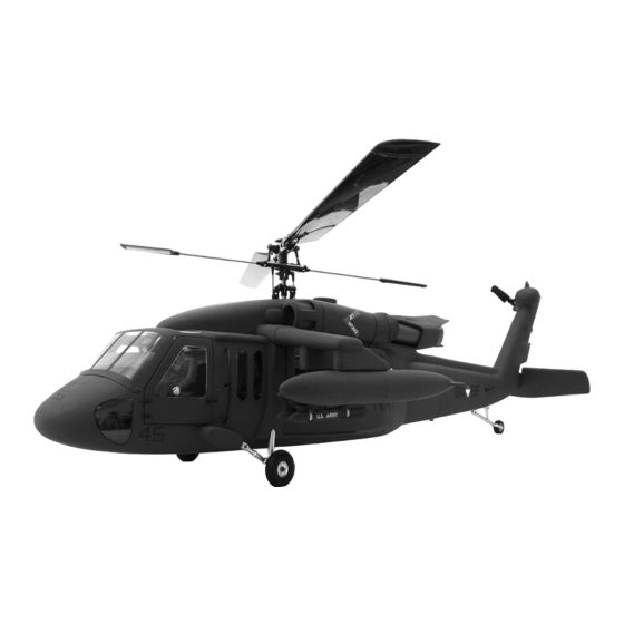
Scale Fuselage UH-60 (Blackhawk, Seahawk, Jayhawk)
600 size
1.
INTRODUCTION
Thank you for buying Roban Model products. The 600 size UH-60 scale fuselage is designed as an easy
to use product. Please read the manual carefully before assembling the model, and follow all
precautions and recommendations located within the manual. Be sure to retain the manual for future
reference, routine maintenance and tuning. The scale fuselage is designed for T-REX 600 Helicopter
series use. You can easily put it on your T-REX 600 for new clothing.
Important Note
Roban Model R/C Helicopters are advanced, high-performance devices, built incorporating the latest
technologies. They are not intended as toys, and improper use can potentially lead to serious injury,
or even fatal accidents. We implore you to read this manual thoroughly before operating these
models. Safety should be your utmost priority - not just your own, but also that of others and your
surroundings when piloting Roban Model products.
Liability Disclaimer:
The manufacturer and the seller cannot accept liability for the operation or misuse of this product.
Roban Model R/C helicopters are intended to be used exclusively by experienced adults in legally
sanctioned flying fields. Once sold, we cannot monitor or control the product's operation or usage.
Operation Guidelines:
Advertisement

Related Manuals for Roban UH-60


Summary of Contents for Roban UH-60
- Page 1 600 size INTRODUCTION Thank you for buying Roban Model products. The 600 size UH-60 scale fuselage is designed as an easy to use product. Please read the manual carefully before assembling the model, and follow all precautions and recommendations located within the manual. Be sure to retain the manual for future reference, routine maintenance and tuning.
- Page 2 Upon assembly of the scale fuselage, the weight and complexity of the structure will increase. To mitigate risk of accidents and damages, we advise against attempting 3D flights. Skill Requirements: The operation of R/C products necessitates a certain level of skill and familiarity. Any damages or dissatisfaction resulting from accidents, modifications, or operational mishaps are not covered under any warranty.
-
Page 3: Contents Of Kit
CONTENTS OF KIT Please check the contents of the kit prior to installation. 1. Tail gearbox 2. Short tail tube 3. Short torque tube 4. Ball link frames 5. Tail shaft gear 6. Tail shaft 7. Tail pushrod 8. Mounting blocks 9. - Page 4 25. Front door windows 26. Middle windows 27. Door grips 28. EVA Distancer 29. Scale antenna 30. Winglets 31. Rockets 32. Fuel tanks 33. Exhaust difusors 34. Diffusor covers 35. Horizontal Wing 36. Wing hinges 37. Screw A3x10 x6 38. Screw M4x18 x3 39.
-
Page 5: Installation
INSTALLATION 3.1. Disassemble the tail boom cover for assembly as shown. 3.2. Use the 3.0 mm hinge pins (15) and clips (18) to assemble the tail gear holder (20). 3.3. Drill holes in the tail boom, then use self-tapping A3x10mm screws (37) to attach the rear landing gear to the tail boom. - Page 6 3.4. Insert the strobe light assembly into the tail light housing and organize the wires neatly. 3.5. Use self-tapping A3x10mm screws to lock the front landing gear set to the fuselage. 3.6. Use screws M4x18mm and 3.0mm hinge pins and clips to secure the front landing gear to the fuselage.
- Page 7 3.7. Use AB glue to adhere the entire tail boom to the tail boom joint on the front fuselage. 3.8. Remove all the doors, then glue the transparent windows in place. 3.9. Install the center instrument panel in the corresponding position on the floorboard with glue.
- Page 8 3.10. Install the instrument panel inside the fuselage and secure it with AB glue. 3.11. Install the seat in the corresponding position on the pilot figure seat. 3.12. As shown in the image, install all the listed accessory parts onto the side frames.
- Page 9 3.13. Install the tail support using the accessory parts. 3.14. Install the rear accessory parts as shown in the image. 3.15. Use the original landing gear screws to secure the provided plastic blocks onto the frame.
- Page 10 3.16. After installing all accessory parts, adjust all frame parameters: servo centers, tail rotor centers, throws, collective pitch curves, etc. 3.17. First disassemble the tail rotor section of the tail boom for easier installation into the fuselage. 3.18. Install the mechanics by inserting it as shown into the fuselage.
- Page 11 3.19. After installing the mechanics, the tail boom gearbox should protrude from the rear of the fuselage. 3.20. Install the previously disassembled tail rotor assembly onto the tail boom gearbox. 3.21. Insert the tail rotor boom support foam into the slot.
- Page 12 3.22. Install the tail rotor pushrods on the tail frame and the triangular lever. 3.23. Install the engine top cover, for properly positioning the mechanics front-to-back and left-to- right. 3.24. After adjusting the position, use washer-head self-tapping A3x16 screws to secure the mechanics to the fuselage floorboard.
- Page 13 3.25. Install the engine top cover. 3.26. Install the engine front cowl. 3.27. Install the front and middle doors again.
- Page 14 3.28. Install the tail boom cover again. 3.29. Install the fixing parts for the stabilizers onto the stabilizers. 3.30. Install the stabilizers onto the tail boom with glue. You can make them servo operated.
- Page 15 3.31. Use AB glue to attach the inner exhaust parts to the outer exhaust housing. 3.32. Glue the entire exhaust assembly onto the corresponding location on the fuselage. 3.33. Use AB glue to attach the missiles and aux tank to their mounts.
- Page 16 3.34. Use self-tapping A3x16 screws to install the missile winglets onto the fuselage. 3.35. Use glue to attach the antennas to the tail boom. 3.36. Use glue to attach the hand holds to the fuselage.
-
Page 17: Spare Part List
4. SPAREPART LIST 600 UH-60 600UH60 黑鹰 UH600PJ001 engine 引擎盖 hatch 600 UH-60 600UH60 黑鹰 UH600PJ002 front 前窗 window 600UH60 黑鹰 600 UH-60 UH600PJ003 全套窗 all windows 600UH60 黑鹰 600 UH-60 UH600PJ004 平尾 tail fin 600UH60 黑鹰 600 UH-60 UH600PJ005 武器... - Page 18 600UH60LED 600 UH-60 UH600PJ012 灯 light kit 600UH60 黑鹰 600 UH-60 UH600PJ013 水印 decals 600 UH-60 600UH60 尾巴 tail UH600PJ014 固定螺丝 mounting hardware 600UH60 短尾 600 UH-60 UH600PJ015 管+轴+拉杆 tail tubes 600 UH-60 600 轴传通用 600WBX01 tail bevel 尾波箱扇齿 gears 600 HH-60 600 轴传通用...
- Page 19 600HH60 红鹰 600 MH-60 MH600PJ013 水印 decals 5. ILLUSTRATION OF READY MOUNTED HELICOPTER Spezifikationen: Länge: 1320mm Höhe: 442mm Breite: 330mm Gewicht: 1000g Passend für Align TREX600ESP und baugleiche Mechaniken We wish you a lot of fun with the fuselage! Copyright 2024 – www.robanmodel.com...
Need help?
Do you have a question about the UH-60 and is the answer not in the manual?
Questions and answers