Table of Contents
Advertisement
Quick Links
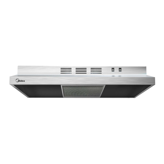
Cooker Hood
USER MANUAL
MVU30W2AST
Warning notices: Before using this product, please read this manual carefully and keep it for future reference.
The design and specifications are subject to change without prior notice for product improvement.
Consult with your dealer or manufacturer for details.
The diagram above is just for reference. Please take the appearance of the actual product as the standard.
Advertisement
Table of Contents

Subscribe to Our Youtube Channel
Related Manuals for Midea MVU30W2AST


Summary of Contents for Midea MVU30W2AST
- Page 1 Cooker Hood USER MANUAL MVU30W2AST Warning notices: Before using this product, please read this manual carefully and keep it for future reference. The design and specifications are subject to change without prior notice for product improvement. Consult with your dealer or manufacturer for details.
-
Page 2: Table Of Contents
THANK YOU LETTER Thank you for choosing Midea! Before using your new Midea product, please read this manual thoroughly to ensure that you know how to operate the features and CONTENTS THANK YOU LETTER SAFETY INSTRUCTIONS SPECIFICATIONS PRODUCT OVERVIEW PRODUCT INSTALLATION... -
Page 3: Safety Instructions
SAFETY INSTRUCTIONS Intended Use The following safety guidelines are intended to prevent unforeseen risks or damage from unsafe or incorrect operation of the appliance. Please check the packaging and appliance on arrival to make sure everything is intact to ensure safe operation. If you find any damage, please contact the retailer or dealer. - Page 4 Important Safety Instructions Save these instructions for future references. WARNING Approved for residential appliances. For residential use only. TO REDUCE THE RISK OF FIRE, Do not attempt to install or operate your ELECTRIC SHOCK, OR INJURY TO appliance until you have read the safety PERSONS, OBSERVE THE FOLLOWING: precautions in this manual.
- Page 5 Important Safety Instructions WARNING WARNING To Reduce The Risk Of Fire Or Electric TO REDUCE THE RISK OF INJURY TO Shock, Do Not Use This Hood With Any PERSONS, IN THE EVENT OF A RANGE External Solid State Speed Control TOP GREASE FIRE, OBSERVE THE Device.
- Page 6 Important Safety Instructions GROUNDING INSTRUCTIONS WARNING-Improper grounding can This appliance must be grounded. In the result in a risk of electric shock. event of an electrical short circuit, ground- Consuit a qualified electrician if the ing reduces the risk of electric shock by grounding instructions are not providing an escape wire for the electric completely understood, or if doubt...
-
Page 7: Specifications
Follow the electrical connector codes and ordinances. manufacturer’s recommended procedure. Aluminum/copper connection must conform with local codes and industry accepted wiring practices. SPECIFICATIONS Product Model MVU30W2AST Voltage 120V~/60Hz Rated Power 70 W Lighting Power E26 LED MAX 9W Motor Power 70 W... -
Page 8: Product Overview
PRODUCT OVERVIEW Important Observe all governing codes and ordinances. Cabinet Dimensions It is the installer’s responsibility to comply ● with installation clearances. Range hood location should be away from ● strong draft areas, such as windows, doors and strong heating vents. Cabinet opening dimensions that are shown ●... - Page 9 Product dimensions unit:inch (200CFM Ducted version) (100CFM Ducted version) (306mm) (240mm) (143mm) (225mm) 6 (176mm) (706mm) (43mm) (230mm) (251mm) (620.75mm)
-
Page 10: Product Installation
PRODUCT INSTALLATION Venting Requirements Do not terminate the vent system into an attic or other enclosed area. ● Do not use a 4'' (102 mm) laundry-type wall cap. Use metal vent only. Rigid metal ● vent is recommended. Plastic or metal foil vent is not recommended. The length of vent system and number of elbows should be kept to a minimum to ●... - Page 11 Note Flexible vent is not recommended. Flexible vent creates both back pressure and air turbulence that greatly reduce performance. Roof Venting Wall Venting Calculating Vent System Length To calculate the length of the system you need, add the equivalent feet (meters) for each vent piece used in the system.
- Page 12 Prepare The Location Note Before making cutouts, make sure there is proper clearance within the ceiling, wall or cabinet. Fitting material is provided to secure the hood to most types of walls and cabinets. However, a qualified technician must verify suitability of the materials in accordance with the type of wall and cabinet.
- Page 13 6. Use 5/64” drill bit and drill 4 pilot holes as shown for top range hood support. NOTE: Make the drill holes on the thin area of the slot. A. Drill pilot hole 7. Install the 4 - 5 mm x 19 mm mounting screws in pilot holes. Leave about ”...
- Page 14 Determine Wiring Hole Location 1. Determine and clearly mark a vertical centerline on the wall and cabinet bottom. A Centerline To wire through top: 2. Mark a line distance (A) from the right of the centerl ine on the underside of the cabinet.
- Page 15 Roof Venting cutout on the underside of cabinet top and bottom: Mark lines from the back wall on the centerline of the underside of cabinet. Mark lines to the right and left of the centerline on the underside of cabinet. Use saber or keyhole saw to cut a rectangular opening for vent.
- Page 16 Roof Venting(7" Circular interface) To make 7 1/2"(190mm) rectangular cutout on the underside of cabinet topand bottom: 1. Mark lines from the back wall on the centerline ofthe underside of cabinet. Mark lines to the right and left of the centerline on the underside of cabinet. Use saber or keyhole saw to cut a rectangular opening for vent.
- Page 17 3. Internal recycle air outlet Use D air outlet,retention A and B materials. Vent Damper Installation Install 3 ” x 10” (8.3 x 25.4 cm) vent damper. Attach to range hood using the indicated screws provided in hardware kit. Install the 3¼” x 10” (8.3 x25.4 cm) rectangular vent transition.
- Page 18 200CFM Ducted version Install Vent System 1. Install vent through the vent opening in upper cabinet. INSTALL RANGE HOOD (Ducted version). Detach the Ø7.08” (Ø 18cm) rectangular vent damper from the package. A.Ø7.08” (Ø 18cm) rectangular vent damper For roof installations, remove the top rectangular vent knockout A. For wall installa- tions, remove the rear rectangular vent knockout B.
- Page 19 Power Supply Cable Installation For direct wire installations, run the home power supply cable according to the National Electric Code or CSA standards and local codes and ordinances. Note Do not reconnect power until the installation is complete. Before starting the installation, remove the vent grill and grease filters. 2.
- Page 20 Make Electrical Connection Warning Electrical Shock Hazard Disconnect power before servicing. Replace all parts and panels before operating. Failure to do so can result in death or electrical shock. 1. Disconnect power. A. White wires B. Black wires C. Green ground wire D.
-
Page 21: Cleaning And Maintenance
Range Hood Controls The hood controls are located at the bottom front section of the unit. Operating the Light Push lamp Switch Operating the Fan Lamp Switch Motor Switch Push Motor Switch :Motor Low Position :Motor High Position :Motor Off CLEANING AND MAINTENANCE Cleaning Warning... - Page 22 To clean or replace grease filter: Take down lamp-chimney,take down screw. According to " " direction loosen Plastic seat. To clean grease filter, soak the filters in hot water using a mild detergent. Rinse well and shake to dry. Note Do not use ammonia.
-
Page 23: Troubleshooting
TROUBLESHOOTING Problem Possible reason Solution The power line and the cable Check the power connections. ● connector is not connected After installation,the properly. unit doesn’t work. The wires from the switches Make sure the wires on the ● are disconnected or loose. switches are connected properly. -
Page 24: Trademarks, Copyrights And Legal Statement
Midea may constitute trademark infringement or unfair competition in violation of relevant laws. This manual is created by Midea and Midea reserves all copyrights thereof. No entity or individual may use, duplicate, modify, distribute in whole or in part this manual, or bundle or sell with other products without the prior written consent of Midea. -
Page 25: Data Protection Notice
European Economic Area. Further information are provided on request. You can contact our Data Protection MideaDPO@midea.com. To exercise your rights such as right to object your personal date being processed for direct marketing purposes, please contact us via MideaDPO@midea.com. To find further information, please follow the QR Code. - Page 28 16173000A22733 V1.0...
Need help?
Do you have a question about the MVU30W2AST and is the answer not in the manual?
Questions and answers