Sign In
Upload
Manuals
Brands
WAGO Manuals
Control Unit
765-4103/100-000
WAGO 765-4103/100-000 Manuals
Manuals and User Guides for WAGO 765-4103/100-000. We have
1
WAGO 765-4103/100-000 manual available for free PDF download: Product Manual
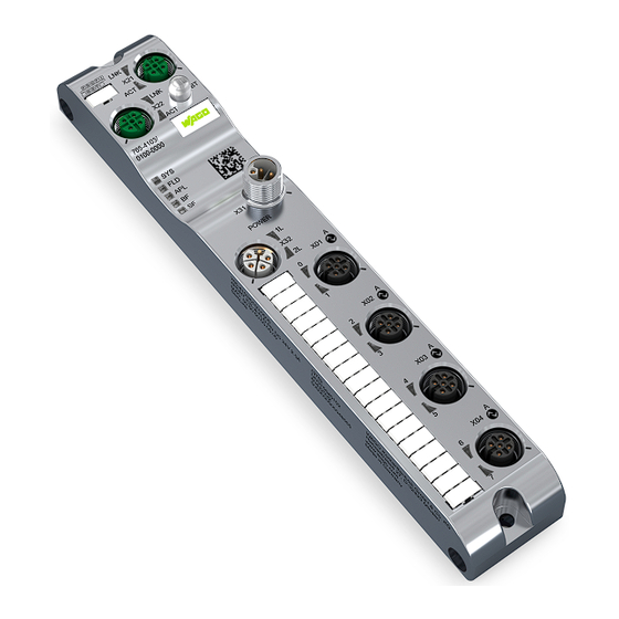
WAGO 765-4103/100-000 Product Manual (150 pages)
I/O System Field
Brand:
WAGO
| Category:
Control Unit
| Size: 8 MB
Table of Contents
Table of Contents
3
Provisions
7
Intended Use
7
Typographical Conventions
8
Safety
11
General Safety Rules
11
Electrical Safety
11
Mechanical Safety
11
Thermal Safety
11
Indirect Safety
12
Overview
13
Table 1 Legend for "View" Figure
14
Properties
14
View
14
Connections
15
Power Supply
15
Table 2 Supply Voltage
15
Circuit Diagram
16
Table 4 ETHERNET Interfaces
16
Table 3 IO-Link (Class A)
16
Communication Interfaces
16
ETHERNET Interfaces
16
Network Connections
16
IO-Link (Master)
16
Technical Data
17
Product
17
Mechanical Data
17
Connection Technology
17
Table 5 Product
17
Table 6 Mechanical Data
17
Table 7 Connection Technology
17
Table 8 IO-Link Port (Class A)
18
Table 9 Total Load
19
Power Supply
20
Table 10 Power Supply
20
Electrical Safety
21
Environmental Conditions
21
Communication
21
Table 11 Electrical Safety
21
Table 12 Environmental Requirements
21
Table 13 Communication
21
Table 14 Communication - PROFINET IO Device
21
Table 15 OPC UA Server
22
Table 16 Communication - Bluetooth Transmitter
22
Derating
23
Regulations and Standards
24
Table 17 Standards and Regulations
24
Approvals
25
Functions
26
Process Image
26
Table 18 Process Data of Digital Inputs and Outputs (Port-Based Assignment)
26
Table 19 Process Data of Digital Inputs and Outputs (Pin-Based Assignment)
26
Table 20 Process Data, IO-Link Port Submodule (DI)
26
Table 21 Process Data, IO-Link Port Submodule (DO)
26
Forcing
27
Table 22 Port Qualifier Information
27
Table 23 Provider and Consumer Status
27
Monitoring Functions
28
Overload Protection
29
Parameterization Tools
29
Overview
29
Table 24 Overview of Parameterization Tools
29
Table 25 Parameterization Overview
30
WAGO IO-Link Configurator
30
WAGO Webserver I/O Field
31
Table 26 Function Overview for WAGO I/O Field Webserver and WAGO IO-Link Modules
31
WAGO I/O Field App
32
Communication Interfaces
33
Profinet
33
OPC UA Server
34
Planning
35
Structure Guidelines
35
Data Security
35
EMC Installations
35
Power Supply Concept
36
Design Power Supply
36
Table 27 Upper Limits for Current on the Individual Pins of the Connections
38
Table 30 Rules for Supply Cables 1 and 2
39
Table 29 Module 765-4103/100-000 - Currents in Supply Cable 2
39
Table 28 Module 765-4103/100-000 - Currents in Supply Cable 1
39
Requirements on the Power Supply
40
Additional Measures
40
Power Supply Examples
41
Settings Options
45
PROFINET Parameters
45
Table 31 "IO-Link Master" Parameters
45
Table 32 Parameters of the "IO-Link XX I / XX O + PQI" Submodule
46
Table 33 "Port Cycle Time
47
Table 34 "DI" (Digital Input) Parameters
48
Table 35 "DO" (Digital Output) Parameters
49
Table 36 Parameters of the "Deactivated" Submodule
50
Setting the PROFINET Configuration
51
Table 37 PROFINET Modules and Submodules
51
Table 38 Port Submodules
51
Transport and Storage
53
Installation and Removal
54
Installation
54
Tools Required for Installation
54
Before Installation
54
Installation Instructions
54
Note on Protecting against Heat Generation by the Product
55
Installation Distances
55
Installation
55
After Installation
55
Grounding
56
Removal
56
Tools Required for Removal
56
Before Removal
56
After Removal
56
General Information on Installation
57
Connection
57
Connect Power Supply
58
Connecting Cables
60
Connecting the Fieldbus
60
Connect Sensors/Actuators
62
Table 39 Connecting an IO-Link Device or Digital Input or Output
64
Commissioning
66
Setting an IP Address
66
Configuration
68
Parameterizing the Module Via PROFINET
68
Selecting the Module
68
Configure the PROFINET Station Name and IP Address
68
Parameterizing Ports
68
Setting Parameters
68
Call WAGO Webserver I/O Field
69
User Interface of the WAGO Webserver I/O Field
69
WAGO Webserver I/O Field
69
Parameterization
69
Maintenance Information
70
Displaying Licenses
70
Opening the Product Information Via WAGO Webserver I/O Field
70
Displaying Port Information
70
Table 40 Data on the "Dashboard" Page
70
Advanced Module and Port Information
70
Displaying Measured Values and Information on Connected IO-Link Devices
71
Table 41 Tabs for Port Information and Settings (IO-Link Ports X01, X02 Etc.)
71
Table 42 Additional Information on the Products Connected to the Selected Port
72
Displaying Port Status Information
73
State
74
Table 43 Possible Values of "State" (Port Status Information)
74
Output Data Length
75
Table 45 Cycle Time of the Master - Bits 6
75
Table 44 Meaning of the Individual Bits
75
Vendor ID
75
Cycle Time
75
Input Data Length
75
Baud Rate
75
Revision ID
75
Quality
75
Device ID
76
Displaying Process Data
76
Parameterizing the Module Via the WAGO I/O Field Webserver
77
Accessing a Connected IO-Link Device
77
Configure Ports
80
Table 46 Port Configuration Settings for IO-Link Devices
80
Table 47 "Port Mode" Drop-Down Menu: Selecting the Operating Mode for Pin 4 of the Selected IO-Link Port
81
Table 48 IQ Behavior Drop-Down Menu - Configuration of Pin 2 (I/Q) for IO-Link Class a De- Vices
82
Table 49 Possible Values of the Inspection Level Parameter
82
Table 51 Setting the Inspection Levels and Backup Levels for Device Check During Validation and Backup
83
Table 50 Possible Values of the Backup Level Parameter
83
Configuring IP Parameters
84
Table 52 Device Configuration Tab - Parameter Overview
84
Storing Maintenance Information
85
Table 53 Maintenance Information
85
Updating Firmware
86
Resetsetting the Module to the Factory Settings
87
Configure Bluetooth
88
Table 54 Options for Resetting the Module to the Factory Settings
88
Table 55 Status of the Last Bluetooth Firmware Update
90
Logging Users on and off and Managing Them
91
Forcing Digital Inputs and Outputs
94
Table 56 Input Options for Forcing for each Pin of a Port
94
Forcing for IO-Link Ports
95
OPC UA Server
97
Parameterizing a Module with the WAGO I/O Field App
97
WAGO I/O Field App
97
WAGO IO-Link Configurator
97
Parameterizing the Product Via OPC UA
98
Identifying Devices
98
Table 57 Identify Devices
98
Setting Device Parameters
99
Setting Port Parameters
99
Table 58 Device-Specific Configuration Parameters
99
Reading Port Process Values
100
Table 59 Port-Specific Configuration Parameters
100
Table 60 Port-Specific IO-Link Process Data
100
Reading Measured Power Values
101
Table 61 Port-Specific Process Data of the Digital Inputs and Outputs
101
Table 62 Device-Specific (Calculated) Measured Current Values
101
Table 63 Device-Specific (Calculated) Measured Temperature Values
101
Table 65 Port-Specific Diagnostics
102
Reading out Diagnostic Information
102
Table 64 Device-Specific (Calculated) Measured Voltage Values
102
Reading Statistics
102
Table 66 Port Specific Statistical Information
103
NTP Client Configuration
104
I/O Forcing Via OPC UA
104
Table 67 NTP Client Configuration
104
Using OPC UA Client
105
Table 68 Input Arguments of the Inputsimulationpin Method
114
Table 69 Output Arguments of the Inputsimulationpin Method
115
Table 70 Input Arguments of the Outputpin Method
116
Table 71 Output Arguments of the Outputpin Method
117
Table 72 Input Arguments of the Iolinkinputsimulation Method
118
Table 73 Output Arguments of the Iolinkinputsimulation Method
118
Table 74 Input Arguments of the Iolinkoutput Method
120
Table 75 Output Arguments of the Iolinkoutput Method
120
Table 77 Output Arguments of the Disableforcing Method
121
Setting the Module Time
121
Table 76 Input Arguments of the Disableforcing Method
121
Diagnostics
122
Diagnostics Via Indicators
122
Table 78 Supply Voltage Status, 1L and 2L
122
Table 79 System Status
122
Table 80 Field LED
122
Table 81 APL LED
123
Table 82 PROFINET IO-Device Status
123
Table 83 LED States - PROFINET IO-Device
123
Table 84 ETHERNET Status
123
Table 85 LED States - ETHERNET Status
124
Table 86 LED States
124
Table 87 IO-Link Port Status (Class A)
124
Table 88 General Alarms
125
Diagnostics Via PROFINET
125
Table 89 IO-Link Master Diagnostic Alarms
126
Table 90 Process Alarms for IO-Link Device Diagnostics
127
Service
128
Resetting to Factory Settings
128
Updating Firmware
128
Decommissioning
129
Disposal and Recycling
129
Table 91 WEEE Mark
129
Appendix
130
Record Data Sets
130
IOL_CALL / IO_LINK_DEVICE (Record 0Xb400)
130
Table 92 Addressing the IO-Link Port with the Slot and Subslot
130
ISDU Read Service
131
Table 93 Structure of IOL_CALL for an ISDU Read Request (Writerecord Request)
132
Table 95 Structure of the IOL_CALL (Readrecord Response and in Case of Error)
133
Table 94 Structure of the IOL_CALL (Readrecord Response and in Case of Success)
133
ISDU Write Service
134
Table 96 Structure of IOL_CALL for an ISDU Write Request (Writerecord Request)
134
Error Handling
136
Table 97 Structure of the IOL_CALL (Readrecord Response and in Case of Success)
136
Table 98 Structure of the IOL_CALL (Readrecord Response and in Case of Error)
136
Table 99 Iol_Error_Pdu Coding
136
Table 100 Port Errors (Error Codes)
137
Table 101 Application-Specific Errors
137
Table 102 "Derived" Errors
139
Installation Regulations Specified by Approvals
140
Operational Description
141
Table 103 Bluetooth ® Transmitter
141
Table 104 Temperature Ranges
142
Table 105 Voltage Ranges
142
Protected Rights
143
List of Tables
144
Advertisement
Advertisement
Related Products
WAGO 7650-654/000-001
WAGO 765-1706/200-000
WAGO 767-4803/000-800
WAGO 761-214
WAGO 767-1201
WAGO 767-5401
WAGO 767-4801/000-800
WAGO WAGO-TO-PASS 761
WAGO 761-112
WAGO 761-110
WAGO Categories
I/O Systems
Control Unit
Power Supply
Switch
Controller
More WAGO Manuals
Login
Sign In
OR
Sign in with Facebook
Sign in with Google
Upload manual
Upload from disk
Upload from URL