Table of Contents
Advertisement
Switch Mode Power Supply
S8VS (15/30/60/90/120/180/240-W Models)
15/30-W Models
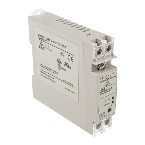
Compact, Thin Power Supplies That Mount
Just About Anywhere to Contribute to
Control Panel Downsizing
• Compact, thin size: 22.5 × 85 × 96.5 mm (W × H × D).
• Three mounting directions
(standard, horizontal, facing horizontal).
• Mounting directly onto the panel is possible.
• Safety standards:
UL508/60950-1/1604, CSA C22.2 No. 14/60950-1/213,
EN50178 (= VDE0160), EN60950-1 (= VDE0805).
60/90/120/180/240-W Models
New Models with Total Run Time Monitor in
Addition to Models with Maintenance
Forecast Monitor
• Compact size: 40 × 95 mm (W × H) (60-W Models).
• Status displayed on 3-digit, 7-segment display.
• Safety standards:
UL508/60950, CSA C22.2 No. 14/60950,
EN50178 (= VDE0160), EN60950 (= VDE0805).
Features Common to All Models
• Mount to DIN Rail.
• Lead-free solder.
Switch Mode Power Supply
S8VS
1
Advertisement
Table of Contents

Related Manuals for Omron S8VS - MODEL 15-30-60-90-120-180-240W


![Power Supply Omron CP1E-N[]S1 Manual](https://static-data2.manualslib.com/product-images/daa/2125691/60x60/omron-cp1e-n-s1-power-supply.jpg)


Summary of Contents for Omron S8VS - MODEL 15-30-60-90-120-180-240W
- Page 1 Compact, Thin Power Supplies That Mount Just About Anywhere to Contribute to Control Panel Downsizing • Compact, thin size: 22.5 × 85 × 96.5 mm (W × H × D). • Three mounting directions (standard, horizontal, facing horizontal). • Mounting directly onto the panel is possible.
-
Page 2: Model Number Structure
S8VS-18024BP 240 W 10 A S8VS-24024 Sinking S8VS-24024A Sourcing S8VS-24024AP Sinking S8VS-24024B Sourcing S8VS-24024BP Note: 1. The output capacity of the S8VS-01505 is 10 W. 2. The output capacity of the S8VS-03005 is 20 W. S8VS Switch Mode Power Supply... -
Page 3: Specifications
1. Refer to the Engineering Data section on page 17 for details. 2. If the V.ADJ adjuster is turned, the voltage will increase by more than +15% of the voltage adjustment range. When adjusting the output voltage, confirm the actual output voltage from the Power Supply and be sure that the load is not damaged. - Page 4 Refer to the Engineering Data section on page 17 for details. If the V.ADJ adjuster is turned, the voltage will increase by more than +15% of the voltage adjustment range (by more than +10% for 240-W models). When adjusting the output voltage, confirm the actual output voltage from the Power Supply and be sure that the load is not damaged.
- Page 5 Vibration resistance 10 to 55 Hz, 0.375-mm single amplitude for 2 h each in X, Y, and Z directions 10 to 150Hz, 0.35-mm single amplitude (5 G max.) for 80 min each in-X, Y, and Z directions Shock resistance 150 m/s , 3 times each in ±X, ±Y, and ±Z directions...
-
Page 6: Block Diagrams
Overcurrent Current detection Drive control circuit circuit circuit Voltage detection circuit Overvoltage detection circuit Photocoupler S8VS-09024 (90-W) Sinking type (S8VS-09024A, S8VS-09024B) Sourcing type (S8VS-09024AP, S8VS-09024BP) S8VS-09024@@ (90-W) Display circuit Switch Display circuit Switch Alarm Alarm DC Low DC Low Arithmetic... - Page 7 Sinking type (S8VS-12024A, S8VS-12024B) Sourcing type (S8VS-12024AP, S8VS-12024BP) S8VS-12024 (120-W) S8VS-12024@@ (120-W) Display circuit Switch Display circuit Switch Alarm Alarm DC Low DC Low Arithmetic Arithmetic operation circuit operation circuit Yrs/kh Yrs/kh Common Rectifier/smoothing circuit Rectifier/smoothing circuit Common Photocoupler Photocoupler Fuse 3.5 A...
- Page 8 Use to adjust the voltage. Note: 1. The fuse is located on the (L) side. It is NOT user-replaceable. 2. This is the protective earth terminal specified in the safety standards. Always ground this terminal. Note: The S8VS-01505 is shown above.
- Page 9 −10% Mounting facing horizontally with S82Y-VS30P The values shown in the above diagram is for reference only. Note: 1. Do not turn ON the power again until the cause of the overvolt- S82Y-VS30P age has been removed. 2. The overvoltage protection of the S8VS-015@@ uses a zener di- ode clamp.
- Page 10 Note: The S8VS-12024A is shown above. setting mode or to increase the set 180-W Models value. 10 Down Key (See note 4.) Use the Down Key to change to the Standard Model Models with Display Monitor setting mode or to decrease the set S8VS-18024 S8VS-18024@@ value.
-
Page 11: Mode Change
Note: 1. Press and hold the (9) Up Key U or (10) Down Key D for two seconds or more to increase or decrease the value rapidly. 2. The S8VS-06024@ is not provided with the setting mode and its parameters are fixed at the shipment setting. - Page 12 ■ Peak Hold Current Reset ■ Multiple Alarms The peak value of the output current (i.e., the peak hold current) can When two or more different alarms occur at the same time be reset on the display. Operation Operation mode Mode Key Press 3 seconds or more.
- Page 13 ”, “ ” and “ ” errors. 2. Operation out of the derating curve area, ventilation error, and incorrect mounting direction are probable as a cause of “ ” error. 3. If the “ ” error state continues for more than three hours, the maintenance forecast monitor function becomes invalid. The Yrs output ((12) Maintenance forecast output terminal (Yrs)) will remain OFF (no continuity between (12) Maintenance forecast output terminal (Yrs) and (13) Alarm output common terminal).
- Page 14 If the maintenance forecast setting L (which can be set arbitrarily time until replacement. from 0.0 to 5.0 years in 0.5-year steps) is set to a value larger than Output two years, the indication automatically changes to a value (L - 0.5)
-
Page 15: Principle Of Operation
When the period left for maintenance that ing rubber and evaporates as time passes since it is manufactured, the power supply forecasts reaches the set value, an alarm is indi- which causes deterioration of characteristics such as decreasing the cated and an output signal is triggered. - Page 16 S8VS-09024B@/S8VS-12024B@/ for the total run time. S8VS-18024B@/S8VS-24024B@ Time Chart The display will appear when the set value for the total run time has Total run time been reached. 50 kh Operation mode Total run time set value reached.
-
Page 17: Overload Protection
■ Overvoltage Protection Consider the possibility of an overvoltage and design the system so that the load will not be subjected to an excessive voltage even if the feedback circuit in the Power Supply fails. When an excessive volt- See note 1. - Page 18 The preset value of detection voltage can be changed in the setting mode. (From 18.5 to 27.5 V (18.5 to 26.3 V for the S8VS-24024@@), in 0.1- V steps. The value is fixed at 20.0 V for the S8VS-06024@.)
- Page 19 Dimensions Note: All units are in millimeters unless otherwise indicated. S8VS-015@@ (15-W) S8VS-030@@ (30-W) (Sliding: 10 max.) 35.2 22.5 (Sliding: 10 max.) 96.4 Note: The illustration is the S8VS-03024 Model. Five, M4 S8VS-06024 (60-W) with square washer 11.3 S8VS-06024@ (60-W) 35.4...
-
Page 20: End Plate
34.9 4.5 (Sliding: 15 max.) Track stopper Track stopper Note: The illustration is the S8VS-24024A Model. ■ DIN Rail (Order Separately) Note: All units are in millimeters unless otherwise indicated. Mounting Rail (Material: Aluminum) PFP-100N PFP-50N 7.3 ± 0.15 35 ±... -
Page 21: Mounting Brackets
Side-mounting Bracket (for 60-, 90-, and 120-W models) S82Y-VS10S Side-mounting Bracket (for 180-W models) S82Y-VS15S Side-mounting Bracket (for 240-W models) S82Y-VS20S Front-mounting Bracket (for 60-, 90-, 120-, 180-, and 240-W models) (See note.) S82Y-VS10F Note: Two required to mount a 240-W model. Type Model Dimensions Appearance... -
Page 22: Safety Precautions
Here, Arrhenius’s Law applies, i.e., the life tally. will be cut in half for each rise of 10°C or the life will be doubled for Heat dissipation will be adversely affected. When the product is each drop of 10°C. The life of the Power Supply can thus be mounted facing horizontally, always place the side with the label fac- increased by reducing its internal temperature. -
Page 23: Charging The Battery
(S8VS-@@@24B@) may be a similar number of years as the maintenance forecast monitor according to some settings. During If a high voltage is applied between an input and the case (FG), it will operation over an extended period of time, periodically check if the... -
Page 24: Din Rail Mounting
DIN Rail Mounting In Case There Is No Output Voltage To mount the Block on a DIN rail, hook portion (A) of the Block onto The possible cause for no output voltage may be that the overcurrent the rail and press the Block in direction (B). - Page 25 S8VS Switch Mode Power Supply...
- Page 26 S8VS Switch Mode Power Supply...
- Page 27 S8VS Switch Mode Power Supply...
- Page 28 CONTRACT, WARRANTY, NEGLIGENCE, OR STRICT LIABILITY. In no event shall the responsibility of OMRON for any act exceed the individual price of the product on which liability is asserted. IN NO EVENT SHALL OMRON BE RESPONSIBLE FOR WARRANTY, REPAIR, OR OTHER CLAIMS REGARDING THE...
Need help?
Do you have a question about the S8VS - MODEL 15-30-60-90-120-180-240W and is the answer not in the manual?
Questions and answers