Omron K3HB Datasheet
Digital indicators k3hb series
Hide thumbs
Also See for K3HB:
- Applications manual (150 pages) ,
- Manual (147 pages) ,
- Technical communications user's manual (147 pages)
Table of Contents
Advertisement
Quick Links
Download this manual
See also:
Manual
Digital Indicators
K3HB Series (Pulse Input Series)
The K3HB Series has been made complete with
the addition of Digital Signal Input Models.
• Easy recognition of judgment results using two-color
display that can be switched between red and green.
• Equipped with a position meter for monitoring
operating status trends.
• External event inputs allows using various
measurement and discrimination applications.
• Series expanded to include DeviceNet models.
• Short body with depth of only 95 mm (see note)
(from behind the front panel).
• UL certification (Certification Mark License).
• CE Marking conformance by third party assessment
body.
• Water-resistant enclosure conforms to NEMA 4X
(equivalent to IP66).
Note: Depth of 97 mm for DeviceNet models.
Refer to Common Precautions on page 30.
Features
Red-Green Display Allows Easy
Recognition of Judgment Results
The measurement value display can be set to switch between red
and green in accordance with the status of comparative outputs. This
means that the status can be easily seen at a distance.
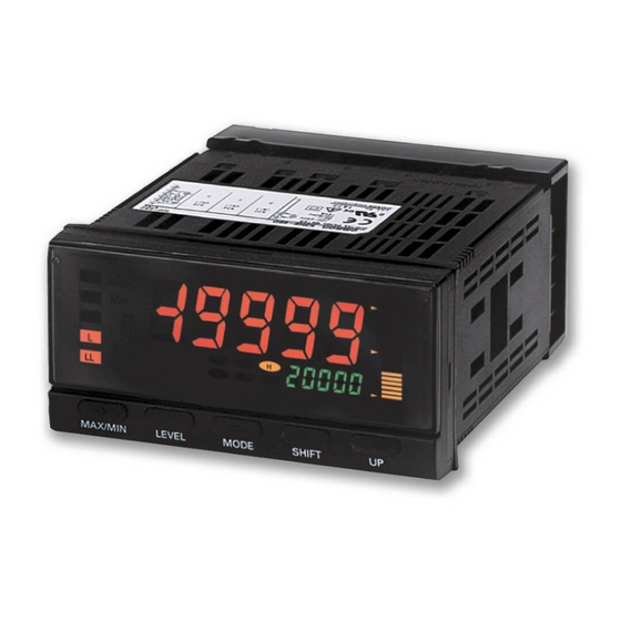
Position Meter Enables Easy Monitoring of
Operating Status Trends
The present value with respect to the measurement or display range
(full scale) can be viewed on a bar display. The operating status can
be grasped intuitively, allowing easy judgment of levels and threshold
values.
HH
Max
Min
H
B
P
L
L
CMW
HH
LL
Hold
T
LL
MAX/MIN
LEVEL
MODE
Note: This function is different from the single-LED display of the K3HB-C.
Short Body with Depth of Only 95 mm
(from Behind the Front Panel)
A short body of only 95 mm (see note) contributes to the
development of slimmer and smaller control panels and installations.
95 mm
Depth:
(See note.)
(The depth is 100 mm when mounted to the terminal cover.)
Note: Depth of DeviceNet models is 97 mm.
Position meter
H
L
SHIFT
UP
27%
shorter
than earlier
models
Digital Indicators
50 kHz High-speed Pulse Measurement
(K3HB-R)
Supports high-speed pulse measurement (up to 50 kHz) of rotary
encoders or any ON/OFF pulse signal, which enables rotational
measurement of objects rotating at high speeds.
Note: No-voltage contacts of up to 30 Hz are supported.
Measurement of Wide Range of Pulse
Interval Times (K3HB-P)
Measures and displays the results of the pulse interval between two
points. The pulse interval measurement range is broad, from 10 ms
to 3,200 s.
High-speed Up/Down Counting Pulse
Measurement (K3HB-C)
Perfect for high-speed measurement of rotary encoders or any
ON/OFF pulse signals. Cumulative pulse input is 50 kHz, quadrature
pulse inputs are 25 kHz, and up/down pulse inputs are 30 kHz.
Note: No-voltage contacts of up to 30 Hz are supported.
K3HB Series (Pulse Input Series)
50 kHz
50 kHz
10 ms to 3200 s
1
Advertisement
Table of Contents

Related Manuals for Omron K3HB


Summary of Contents for Omron K3HB
- Page 1 Operating Status Trends The present value with respect to the measurement or display range (full scale) can be viewed on a bar display. The operating status can Note: No-voltage contacts of up to 30 Hz are supported. be grasped intuitively, allowing easy judgment of levels and threshold values.
- Page 2 Digital Indicators are used in a wide variety of applications, from an electronic measurement value display or equipment/device operating status display to a host communications interface in monitoring and control systems. OMRON provides a complete lineup for a variety of input and control output applications to meet all your application requirements.
- Page 3 Note: The applications provided in this catalog are intended as reference only. Do not attempt to use any of them in real systems without first confirming machine and device functions and safety. For applications that require safety, ensure that there is sufficient leeway in ratings and performances, install fail-safe measures, and take any other safety measures required by the application.
-
Page 4: Model Number Structure
(12 VDC±10%, 80 mA) (See note 2.) 24 VAC/VDC: 24 VAC/VDC L2A: Linear voltage output (DC0(1)-5 V, 0 to 10 V) + Sensor power supply Optional Board (12 VDC±10%, 80 mA) (See note 2.) Sensor power supply (12 VDC ±10%, 80 mA) -
Page 5: Specifications
(Hirose HR31-5.08P-5SC(01)) and crimp terminals (Hirose HR31-SC-121) (See note 3.) Note: 1. DC power supply models require a control power supply capacity of approximately 1 A per Unit when power is turned ON. Particular attention is required when using two or more DC power supply models. The OMRON S8VS-series DC Power Supply Unit is recommended. - Page 6 15% to 95% or 95% to 15%.) Linear output response time Functions F1 to F6: 110 ms max. (time until the final analog output value is reached when there is a forced sudden change in the input signal from 15% to 95% or 95% to 15%.) Insulation resistance 20 M min.
-
Page 7: Operation
The basic principle used by the Digital Indicator to calculate the rotation speed (rpm) display is to count the ON/OFF time (T) for input sensor or other device inputs using the internal system Function name Function No. - Page 8 Function Operation Operation image (application) Measuring the speed ratio between two rollers Multiples input B divided by input A ( ) by 100 and Absolute displays the ratio as a percentage (%). ratio Display unit: % PASS Warning Multiplies the error between input A and input B...
- Page 9 This period is called the auto- coefficient. This coefficient is called the prescale value.
- Page 10 (12 VDC±10%, 80 mA) (See note 2.) 24 VAC/VDC: 24 VAC/VDC L2A: Linear voltage output (DC0(1)-5 V, 0 to 10 V) + Sensor power supply Optional Board (12 VDC±10%, 80 mA) (See note 2.) Sensor power supply (12 VDC ±10%, 80 mA)
- Page 11 (Hirose HR31-5.08P-5SC(01)) and crimp terminals (Hirose HR31-SC-121) (See note 3.) Note: 1. DC power supply models require a control power supply capacity of approximately 1 A per Unit when power is turned ON. Particular attention is required when using two or more DC power supply models. The OMRON S8VS-series DC Power Supply Unit is recommended.
- Page 12 Must be able to properly switch load currents of 5 mA or less. Comparative output response 2 ms max. (time until the comparative output is made when there is a forced sudden change in the input signal time (transistor output)
- Page 13 ■ Functions (Operating Modes) F1 to F6 These functions use the internal system clock to measure the time between pulses or the pulse ON time and then display time measurements or a variety of other calculations. Example: F1 Passing Speed The time (T) between input A pulse and input B pulse is measured by the internal system clock.
- Page 14 ■ What Is Prescaling? To make calculations using the input pulse to display the passing speed between two points, the distance between the two points and the display unit must be set and the internally measured time multiplied by a certain coefficient. This coefficient is called the prescale value. (For information on settings details, refer to the User's Manual.)
- Page 15 Note: No-voltage contacts of up to 30 Hz are supported. • The count value can be converted to any value. The length equivalent for any pulse can be set to any desired value. This is effective for feed amount and position monitor displays.
- Page 16 (Hirose HR31-5.08P-5SC(01)) and crimp terminals (Hirose HR31-SC-121) (See note 3.) Note: 1. DC power supply models require a control power supply capacity of approximately 1 A per Unit when power is turned ON. Particular attention is required when using two or more DC power supply models. The OMRON S8VS-series DC Power Supply Unit is recommended.
- Page 17 95% or 95% to 15%) Linear output response time 10 ms max. (time until the final analog output value is reached when there is a forced sudden change in the input signal from 15% to 95% or 95% to 15%) Insulation resistance 20 M min.
- Page 18 Symbol Input method No-voltage input Short-circuit Open 2. Requires at least half the minimum signal width. If there is less than half, a ±1 count error may occur. Input Type Setting NO: Voltage pulse high NC: Voltage pulse low No-contact or voltage pulse input 00...
- Page 19 1. The prescale value for the K3HB-C is set using the mantissa X exponent Y, so the prescale value = 2.0000 × 10°, X = 2.000, and Y = 00. 2. Next, set the decimal point position for one digit to the right of the decimal point: 0.5 m 250 pulses K3HB-C...
-
Page 20: Common Specifications
Resolution Approx. 10,000 Output error ±0.5% FS ±0.5% FS (±0.15 V for 1 V or less and no output for 0 V) Serial Communications Output BCD Output I/O Ratings (Input Signal Logic: Negative) Item Type RS-232C, RS-485 Communications method Half duplex... -
Page 21: Devicenet Communications
Allocate any data, such as DeviceNet-specific parameters and variable area for Digital Indicators. Input area: 2 blocks, 60 words max. Output area: 1 block, 29 words max. (The first word in the area is always allocated for the Output Execution Enabled Flags.) Message Explicit message communications... -
Page 22: Terminal Arrangements
The BCD COMMON is shared. The pins indicated in the above diagram as blank (white) boxes have been removed. * Only one of the following can be used for each Digital Indicator: communications, BCD, or DeviceNet. Contact Outputs Transistor Outputs... - Page 23 (manufactured by DDK) COMMON Stand: 17L-002A (manufactured by DDK) Note: The BCD Output Cable has a D-sub plug. Cover: 17JE-37H-1A (manufactured by DDK); Connector: equivalent to 17JE-23370-02 (D1) (manufactured by DDK) Special Cable (for Event Inputs with 8-pin Connector) Model...
-
Page 24: Internal Block Diagram
Note: 1. The above values were obtained under test conditions with the standard mounting. The derating curve will vary with the mounting conditions, so be sure to adjust accordingly. 2. Internal components may be deteriorated or damaged. Do not use the Digital Indicator outside of the derating range (i.e., do not use it in the area labeled (1), above). -
Page 25: Continuous Data Output
Digital Indicator narrow pitch connector (manufactured by Honda Tsushin Kogyo Co., Ltd.). Refer to the following User's Manual for application precautions and other information required when using the Digital Indicator: K3HB-R/P/C Digital Indicator User's Manual (Cat. No. N136) The manual can be downloaded from the following site in PDF format: OMRON Industrial Web http://www.fa.omron.co.jp... -
Page 26: Component Names And Functions
Level/bank display Position meter In RUN level, displays the bank if the bank function is Displays the position of the PV ON. (Turns OFF if the bank function is OFF.) with respect to a desired scale. -
Page 27: Wiring Precautions
• Use the crimp terminals suitable for M3 screws shown below. 5.8 mm max. 5.8 mm max. 3. Insert the adapter into the grooves on the left and right sides of the rear case and push until it reaches the panel and is fixed in Unit Stickers (included) place. -
Page 28: Main Functions
R P C Function Auto-zero Times The K3HB-R has the following six functions for receiving and The frequency is forced to zero if there is no pulse input for a set displaying input pulses. period. F1: Rotation (rpm)/circumferential speed F2: Absolute ratio... - Page 29 Display Color Selection Prevents comparative outputs from chattering when the The present value display color can be set to green or red. The color measurement value fluctuates slightly near the set value. of the present value can also be switched according to the comparative output.
-
Page 30: Precautions For Safe Use
6 to 8 mm) Perform correct setting of the product according to the 9. In order to prevent inductive noise, wire the lines connected to the application. Failure to do so may occasionally cause product separately from power lines carrying high voltages or unexpected operation, resulting in minor or moderate currents. - Page 31 Indicator 2 conductors with shield 4. If a noise filter is used for the power supply, check the voltage and current, and install the noise filter as close to the product as possible. 5. Reception interference may occur if the product is used close to a radio, television, or wireless.
-
Page 32: Warranty And Limitations Of Liability
Warranty and Limitations of Liability ■ WARRANTY OMRON's exclusive warranty is that the products are free from defects in materials and workmanship for a period of one year (or other period if specified) from date of sale by OMRON. OMRON MAKES NO WARRANTY OR REPRESENTATION, EXPRESS OR IMPLIED, REGARDING NON-INFRINGEMENT, MERCHANTABILITY, OR FITNESS FOR PARTICULAR PURPOSE OF THE PRODUCTS.
Need help?
Do you have a question about the K3HB and is the answer not in the manual?
Questions and answers