Table of Contents
Advertisement
Quick Links
Advertisement
Table of Contents

Related Manuals for Omron K3HB-C


Summary of Contents for Omron K3HB-C
- Page 1 Cat. No. N136-E1-01B K3HB-R/-P/-C Digital Indicators USER’S MANUAL...
- Page 2 Notice (1) All rights reserved. No part of this manual may be reprinted or copied without the prior written permission of OMRON. (2) The specifications and other information contained in this manual are subject to change without notice in order to make improvements.
- Page 3 The following are some examples of applications for which particular attention must be given. This is not intended to be an exhaustive list of all possible uses of the products, nor is it intended to imply that the uses listed may be suitable for the products.
- Page 4 PERFORMANCE DATA Performance data given in this manual is provided as a guide for the user in determining suitability and does not constitute a warranty. It may represent the result of OMRON's test conditions, and the users must correlate it to actual application requirements.
- Page 5 Safety Precautions ● Definition of Precautionary Information The following notation is used in this manual to provide precautions required to ensure safe usage of the product. The safety precautions that are provided are extremely important to safety. Always read and heed the information provided in all safety precautions.
- Page 6 ● Precautions WARNING Do not touch the terminals while power is being supplied. Doing so may possibly result in electric shock. Make sure that the terminal cover is installed before using the product. Always provide protective circuits in the network. Without protective circuits, malfunctions may possibly result in accidents that cause serious injury or significant property damage.
- Page 7 CAUTION Make sure that the product will not be adversely affected if the DeviceNet cycle time is lengthened as a result of changing the program with online editing. Extending the cycle time may cause unexpected operation, occasionally resulting in minor or moderate injury, or damage to the equipment.
- Page 8 (10) Ensure that the rated voltage is achieved no longer than 2 s after turning the power ON. (11) Allow the product to operate without load for at least 15 minutes after the power is turned ON.
- Page 9 (16) Do not connect anything to unused terminals. (17) Output turns OFF when the mode is changed or settings are initialized. Take this into consideration when setting up the control system. (18) Install an external switch or circuit breaker that complies with applicable IEC60947-1 and IEC60947-3 requirements and label them clearly so that the operator can quickly turn OFF the power.
- Page 10 Signal input 2 conductors with shield (3) If a noise filter is used for the power supply, check the voltage and current, and install the noise filter as close to the product as possible. (4) Reception interference may occur if the product is used close to a radio, television, or...
- Page 11 ● Revision History The revision code of this manual is given at the end of the catalog number at the bottom left of the back cover. Cat. No. N136-E1-01B Revision code Date Pages and changes October 2004 Original production March 2005 Page 2-4: Changed “B4”...
- Page 12 Describes the mounting and wiring required before using the product. Section 3 Basic Application Methods Shows typical applications for the product. Also shows wiring and parameter settings which enables the user to understand how to use the product from practical examples. Section 4 Initial Setup Describes the initial setup process when using this product.
- Page 13 ● Settings Data Notation The letters of the alphabet in settings data are displayed as shown below. ● Applicable Model Notation The following symbols are used to indicate the applicable models for specific functions. K3HB-R@@-@@@ K3HB-P@@-@@@ K3HB-C@@-@@@...
-
Page 14: Table Of Contents
3-11 Measuring the Feed Length of a Sheet: K3HB-C....... . - Page 15 5.30 Using Prescale/Comparative Set Value Banks ........
-
Page 16: Section 1 Outline
Section 1 Outline 1.1 Main Functions and Features of the K3HB ........ 1.2 Component Names and Functions of the K3HB-R/P....1.3 Component Names and Functions of the K3HB-C ....1.4 Internal Block Diagram .............. -
Page 17: Main Functions And Features Of The K3Hb
Section 1 Outline 1.1 Main Functions and Features of the K3HB Measurement Functions of the K3HB-R Functions of the K3HB-P Functions of the K3HB-C The K3HB-R has the following The K3HB-P has the following The K3HB-C has the following six functions for reading and... - Page 18 1.1 Main Functions and Features of the K3HB Outputs Comparative output pattern Hysteresis Output refresh stop The comparative output Prevents comparative output Holds the output status when pattern can be selected as chattering when the comparative results outputs standard output, zone output, measurement value fluctuates other than PASS turn ON.
- Page 19 Any bank setting can be minimum measurement banks can be selected using copied to all banks. values. the keys on the front of the Unit or by external inputs. Groups of comparative set values can be set and can be selected as groups.
-
Page 20: Component Names And Functions Of The K3Hb-R/P
Turns ON when the maximum value or minimum value is displayed in RUN indicator level. Level/bank display In RUN level, displays the bank if the bank function is ON. (Turns OFF if the bank function is OFF.) In other levels, displays the current level. Status indicators Hold: Turns ON/OFF when the hold input turns ON/OFF. -
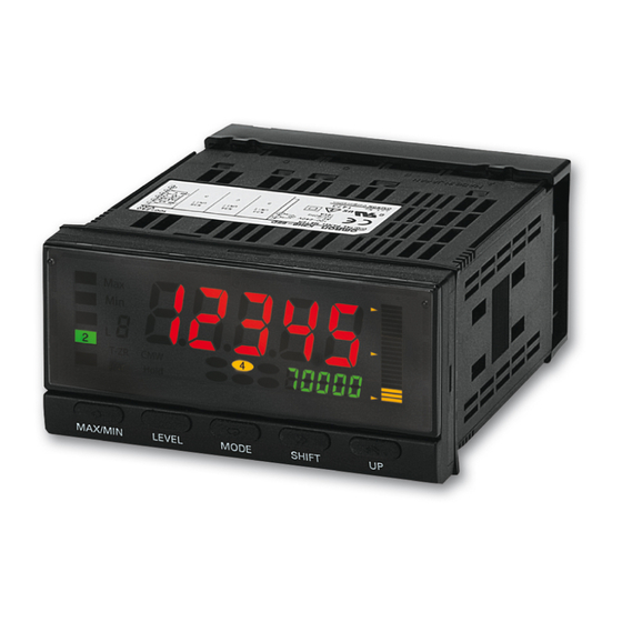
Page 21: Component Names And Functions Of The K3Hb-C
Turns ON when a parameter for which teaching can be performed is indicators displayed. 5, 4, 3, 2, or 1: Turns ON when the comparative values 5, 4, 3, 2, or 1 is displayed in the RUN level. MAX/MIN Key Used to switch the display between the PV, maximum value, and minimum value and to reset the maximum and minimum values. -
Page 22: Internal Block Diagram
1.4 Internal Block Diagram 1.4 Internal Block Diagram Waveform Pulse input Pulse input Keys shaping circuit circuit EEPROM Indications Input circuit Drive Transistor Drive BCD I/O Output circuit circuit output circuit Transistor output circuit Micro- computer Drive Digital input Waveform... - Page 23 Section 1 Outline...
-
Page 24: Section 2 Preparations
Section 2 Preparations 2.1 Mounting ..................2.2 Using I/O.................. -
Page 25: Mounting
Section 2 Preparations 2.1 Mounting ■ External Dimensions 101.2 Character size for main display (mm) PV display SV display 95 (DeviceNet models: 97) ■ Panel Cutout Dimensions 120 min. +0.8... - Page 26 Insert watertight packing around the Unit to make the mounting watertight. Watertight packing Insert the adapter into the grooves on the left and right sides of the rear case and push until it reaches the panel and is fixed in place.
-
Page 27: Using I/O
* Attach the provided crimp terminals. The BCD COMMON is shared. The pins indicated in the above diagram as blank (white) boxes have been removed. *Only one of RS-232C/RS-485 communications, BCD, or DeviceNet can be used by each Digital Indicator. Event Input Pulse Inputs... - Page 28 Use an SELV power supply with overcurrent protection for the DC power supply. An SELV power supply has double or reinforced insulation between the input and output, an output voltage of 30 V rms and 42.4 V peak, and is 60 VDC or less.
- Page 29 Section 2 Preparations ● Linear Outputs Linear currents and voltages are output between terminals B1 to B2 and between B3 to B4. Connect a load within the specified range. Linear output Circuit Diagrams Linear voltage output 5 k min. Linear current output...
- Page 30 2.2 Using I/O ● Comparative Outputs Comparative outputs are output to terminals B1 to B3 and C1 to C6. Connect loads within specifications. The electrical life expectancy of the relays is 100,000 operations. K3HB-C outputs are enclosed in parentheses (OUT*).
- Page 31 Section 2 Preparations Transistor Outputs <K34-T1> NPN Output Models HH (OUT5) H (OUT4) PASS (OUT3) L (OUT2) LL (OUT1) <K34-T2> PNP Output Models HH (OUT5) H (OUT4) PASS (OUT3) L (OUT2) LL (OUT1)
- Page 32 2.2 Using I/O ● Event Inputs Input control signals. The configuration is shown below. Delays measurement until set time S-TMR See page 5-34. expires. Holds measurement value, maximum HOLD value, minimum value, and output See page 5-48. status. Clears maximum value, minimum RESET See page 5-33.
- Page 33 Section 2 Preparations ● Pulse Inputs Open Collector Inputs Input the signals to be measured. The following diagram shows the inputs capable of being measured by each model. Note: E3 and E6, as well as B6 are internally connected. Circuit Diagram...
- Page 34 2.2 Using I/O Voltage Pulse Inputs Input the signals to be measured. The following diagram shows the inputs capable of being measured by each model. Voltage Voltage Note: E3 and E6, as well as B6 are internally connected. Circuit Diagram...
- Page 35 Section 2 Preparations PNP Inputs Input the signals to be measured. The following diagram shows the inputs capable of being measured by each model. Note: E3 and E6, as well as B5 are internally connected. Circuit Diagram E2, E5 E3, E6...
-
Page 36: Section 3 Basic Application Methods
3.1 Monitoring Roller Speed: K3HB-R ..........3.2 Monitoring Conveyor Speed Difference: K3HB-R ...... 3.3 Monitoring Conveyor Line Passing Time: K3HB-R ....3.4 Measuring the Operation Time of a Press: K3HB-P ....3.5 Measuring Workpiece Passing Time between Points A and B: K3HB-P.................. -
Page 37: Monitoring Roller Speed: K3Hb-R
3.1 Monitoring Roller Speed: K3HB-R Advantages of Using the K3HB-R • Monitors roller speed by using a proximity sensor to detect the teeth on a gear attached to the end of the roller. • Outputs four comparison levels corresponding to the roller speed: LL, L, H, and HH. - Page 38 Input type A No-contact (NO) ps. ax 0. 1250 Prescale AX ps. ay 10 00 Prescale AY Prescale value ( ) = 1/8 = 0.125 = 0.125 ,,,,, Decimal point No decimal point position out-p nomal Comparative Standard outputs...
-
Page 39: Monitoring Conveyor Speed Difference: K3Hb-R
NPN open collector rotary encoders. • Outputs four comparison levels corresponding to the conveyor speed: LL, L, H, and HH. • A green display indicates operation within the correct range, and a red display indicates operation not within the correct range. Encoder... - Page 40 3.2 Monitoring Conveyor Speed Difference: K3HB-R ■ Settings for the K3HB-R RUN Level Parameter Characters Remarks value Comparative ✽ set value HH Control example for the following Comparative settings: ✽ set value H HH alarm: 100 rpm H alarm: 50 rpm Comparative ✽...
- Page 41 Section 3 Basic Application Methods Display Adjustment Level Parameter Characters Set value Remarks color grn-r Display color PASS range: Green, selection LL, L, H, and HH ranges: disp Display value Present value selection pos-t Position meter Deviation display type pos-h...
-
Page 42: Monitoring Conveyor Line Passing Time: K3Hb-R
3.3 Monitoring Conveyor Line Passing Time: K3HB-R Advantages of Using the K3HB-R • Displays the passing time to tenths of a second (00.0 s) using a rotary encoder that outputs 100 pulses/rotation. • The prescale value is obtained using the following formula, assuming a roller circumference ( d of 0.125 m and processing... - Page 43 Remarks value 60. 0 Comparative ✽ set value H 10. 0 Comparative ✽ set value L ✽ Check on the status displays. Initial Setting Level ( Parameter Characters Set value Remarks func Function Passing time in-ta Input type A No-contact (NO) ps.
-
Page 44: Measuring The Operation Time Of A Press: K3Hb-P
Advantages of using the K3HB-P • Sensor ON time is measured using a through-beam photoelectric sensor. • Displays the measurement value to tenths of a second (00.0 s) with the display unit of the K3HB-P set to seconds. K3HB-P Connections Diagram... - Page 45 Remarks value 45. 0 Comparative ✽ set value H 35. 0 Comparative ✽ set value L ✽ Check on the status displays. Initial Setting Level ( Parameter Characters Set value Remarks func Function Time band in-ta Input type A No-contact (NO) ps.
-
Page 46: Measuring Workpiece Passing Time Between Points A And B: K3Hb-P
3.5 Measuring Workpiece Passing Time between Points A and B: K3HB-P Advantages of Using the K3HB-P • Measures the time from when sensor A turns ON until sensor B turns ON. • Displays the measurement value to tenths of a second (00.0 s) with the display unit of the K3HB-P set to seconds. - Page 47 Remarks value 45. 0 Comparative ✽ set value H 35. 0 Comparative ✽ set value L ✽ Check on the status displays. Initial Setting Level ( Parameter Characters Set value Remarks func Function Time difference in-ta Input type A No-contact (NO)
-
Page 48: Measuring The Feed Length Of A Sheet: K3Hb-C
Advantages of using the K3HB-C • Displays the measurement value to tenths of a millimeter (0000.0 mm) using a rotary encoder that outputs 250 pulses to measure a feed length of 0.5 m. • Outputs comparative output OUT1 when the measurement value is 500.0 or higher. - Page 49 Remarks value 500. 0 Comparative set ✽ value OUT1 700. 0 Comparative set ✽ value LOUT2 ✽ Check on the status displays. Initial Setting Level ( Parameter Characters Set value Remarks func Function Phase differential inputs in-ta Input type A...
-
Page 50: Counting The Number Of Workpieces: K3Hb-C
3.7 Counting the Number of Workpieces: K3HB-C Advantages of Using the K3HB-C • Detects and counts workpieces on a conveyor. • Using the prescale value banks, two units can be counted as a single workpiece, 4 units can be counted as a single workpiece, etc. - Page 51 Bank Event inputs selection *The Setting Level Protect parameter (set.pt) must be set to 0 (0), and the Move to Advanced Function Setting Level parameter (amov) to 0169 (-0169) to enable moving to the advanced function setting level. Initial Setting Level (...
- Page 52 Bank 0 or bank 1 (See note.) sv0. o1 Comparative set value 0 OUT1 sv1. o1 Comparative set value 1 OUT1 Note When comparative set value bank 0 is set, the comparative set value 0 OUT5 settings are performed next. 3-17...
- Page 53 Section 3 Basic Application Methods 3-18...
-
Page 54: Section 4 Initial Setup
Section 4 Initial Setup 4.1 Initial Setup Example for the K3HB-R........4.2 Initial Setup Example for the K3HB-P ........4.3 Initial Setup Example for the K3HB-C........ -
Page 55: Initial Setup Example For The K3Hb-R
• The display will show “0”. B Set the function to F1 (rpm/circumferential speed). 1. Move to the initial setting level by pressing the L [LEVEL] Key for at least 3 s (operation will stop). 2. Set “func” to “f1” and press the [MODE] Key. - Page 56 F Set comparative set value H to 700 and set comparative set value L to 500. 1. Return to the RUN level by pressing the L [LEVEL] Key for at least 1 s. (Start operation.) 2. Press the M [MODE] Key several times to change the SV display status to “H”...
-
Page 57: Initial Setup Example For The K3Hb-P
• The display will show “-----”. B Set the function to F1 (passing speed). 1. Move to the initial setting level by pressing the L [LEVEL] Key for at least 3 s (operation will stop). 2. Set “func” to “f1” and press the [MODE] Key. - Page 58 F Set comparative set value H to 0.700 and set comparative set value L to 0.500. 1. Return to the RUN level by pressing the L [LEVEL] Key for at least 1 s. (Start operation.) 2. Press the M [MODE] Key several times to change the SV display status to “H”...
-
Page 59: Initial Setup Example For The K3Hb-C
• The display will show “0”. B Set the function to F2 (phase differential inputs). 1. Move to the initial setting level by pressing the L [LEVEL] Key for at least 3 s (operation will stop). 2. Set “func” to “f2” and press the [MODE] Key. - Page 60 G Set comparative set value OUT1 to 500.0 and set comparative set value OUT2 to 700.0. 1. Return to the RUN level by pressing the L [LEVEL] Key for at least 1 s. (Start operation.) 2. Press the M [MODE] Key several times to change the SV display status to “2”...
- Page 61 Section 4 Initial Setup...
-
Page 62: Section 5 Functions And Operations
5.18 No Output before PASS Range..........5-55 5.19 Performing Linear Output............5-57 5.20 Changing the Display Refresh Period........5-60 5.21 Setting a Compensation Value for the Measurement Value ..5-61 5.22 Holding Measurement Values............ 5-63 5.23 Holding Maximum and Minimum Values........5-65 5.24 Changing Normal Display Values to Maximum and... -
Page 63: Knowledge Required For Setting Parameters
Section 5 Functions and Operations Knowledge Required for Setting Parameters ■ About Levels Levels are groups of parameters. Levels for the K3HB are classified as follows: Important Depending on the level, measurements may continue Measurement to be executed or may be... - Page 64 Knowledge Required for Setting Parameters To change a parameter, move to the level where that parameter is found. The current level is shown on the bank/level display when moving between levels. Level/bank Level display Protect level 0 to 7 RUN level (Lights only when banks are used.)
- Page 65 Press the L [LEVEL] and M [MODE] Keys in RUN level for at least 1 s. The PV display will start to flash. Press the same keys for at least 2 s to move to protect level. Press the L [LEVEL] and M [MODE] Keys for at least 1 s to return to RUN level.
- Page 66 Refer to "5.34 Limiting Key Operations" (P.5-84) for the procedure to release protection. A Move to the initial setting level, press the M [MODE] Key several times to display the “amov” (move to advanced function setting level) parameter.
- Page 67 D Press the M [MODE] Key to switch to the next parameter. • The changed set value is stored in the internal memory. • If no key is pressed at step C for 5 s,* the set value is registered and the display automatically returns to monitor status.
- Page 68 123.0 122.0 *1 If no key is pressed for 5 seconds, the set value is registered and the display returns to monitor status. *2 Use the S [SHIFT] and U [UP] Keys to set the set value. Displayed Comparative Set Values...
- Page 69 A Press the M [MODE] Key several times to display the 123.4 comparative set value to be changed. :9999 • One of the values between HH and LL will flash, according to the displayed comparative set value. B Press the S [SHIFT] Key to make the SV display flash. 123.4 •...
-
Page 70: Setting The Function For The K3Hb-R
Alarm outputs Operation Configuration (Application) • Basic Operation The input frequency of input A is multiplied by 60 and the rotational speed is displayed in rpm. Setting a prescale value enables the measurement value to be displayed in any unit. - Page 71 Circumferential length per rotation Example: This example shows the prescale value and the prescale set values for displaying the speed of a roller using a proximity sensor that outputs five pulses per rotation. Prescale value ( ) = 1/5 = 2.0 Prescale value of Input A, X (mantissa): ps.
- Page 72 100 pulses per rotation. (The circumferential length of the rotary encoder is 0.125 m.) Prescale value of Input A ( ) = 0.125/100 = 0.00125 = 1.2500 Prescale value of Input B ( ) = 0.125/100 = 0.00125 = 1.2500 Prescale value of Input A, X (mantissa): ps.
- Page 73 Encoder PASS Alarm outputs Operation Configuration (Application) • Basic Operation The difference between the speed of input A and the speed of input B is displayed. The measurement value can be obtained using the following formula: D = fb fa: Frequency A (Hz)
- Page 74 Operation Configuration (Application) • Basic Operation The flow rate ratio (%) of input B is displayed on the basis of the frequency of input A and the frequency of input B. The measurement value can be obtained using the following...
- Page 75 Prescale value Calculated value Display unit Passing time L/( d/N) N: Pulses per rotation d: Circumferential length per rotation L: Length of processing stage * When fa is , an overflow at the upper limit will be displayed. 5-14...
- Page 76 Rotational difference Flow rate ratio Passing time Parameter Setting Procedure A Press the L [LEVEL] Key for at least 3 s in RUN level to move to func the initial setting level. 3 s min. 0” is displayed on the level/bank display to indicate the initial •...
-
Page 77: Setting The Function For The K3Hb-P
Operation Configuration (Application) • Basic Operation The reciprocal of the time T (s) from the turning ON of input A to the turning ON of input B is multiplied by 60 and the workpiece passing speed between points A and B is displayed. - Page 78 ■ F2: Cycle Measuring Feed Cycles for Parts Operation Configuration (Application) • Basic Operation The time T (s) from one input A ON to the next is displayed. The measurement value can be obtained using the following formula: D = T...
- Page 79 Length of Workpiece Steps Operation Configuration (Application) • Basic Operation The time T (s) from input A ON to input B ON is displayed. D = T T: Time from input A rising edge to input B rising edge (s)
- Page 80 Measurement value No measurement *TR: Recovery Time The time required from the end of one measurement until completing preparations for the next measurement. Allow at least 1 ms. Referring to the following table, specify the prescale value corresponding to the desired display unit.
- Page 81 Encoder To PLC Operation Configuration (Application) • Basic operation Displays the number of input A pulses while input B is ON. The measurement value can be obtained using the following formula: D = C C: Number of pulses of input A while input B is ON...
- Page 82 Encoder PASS Alarm outputs Operation Configuration (Application) • Basic Operation The number of input A pulses from one input B rising edge to the next is displayed. The measurement value can be obtained using the following formula: D = C...
- Page 83 Time band Measuring length Interval Parameter Setting Procedure A Press the L [LEVEL] Key for at least 3 s in RUN level to move to func the initial setting level. 0” is displayed on the level/bank display to indicate the initial •...
-
Page 84: Setting The Function For The K3Hb-C
B pulses. The count is incremented on the rising edge of input A and decremented on the rising edge of input B. When both inputs A and B turn ON at the same time, the count does not change. The measurement value can be obtained using the following formula:... - Page 85 This function is normally used when connected to an incremental rotary encoder. While input A is OFF, the count is decremented on the falling edge of input B and incremented on the rising edge of input B. The measurement value can be obtained using the following formula:...
- Page 86 The outputs are also held. Resetting the Display Value The display value can be zeroed by turning ON the RESET input or press the MAX/MIN Key for 1 second or longer. While the RESET input is ON, measurement is not performed, the display shows “-----”, and all outputs are OFF.
- Page 87 Phase differential inputs Pulse counting input Parameter Setting Procedure A Press the L [LEVEL] Key for at least 3 s in RUN level to move to func the initial setting level. 0” is displayed on the level/bank display to indicate the initial •...
-
Page 88: Setting Input Types
Note: Not displayed on the K3HB-C when F3 has been selected. Parameter Setting Procedure: Input Type The following procedure shows an example using the K3HB-R. A Press the L [LEVEL] Key for at least 3 s in RUN level to move to func the initial setting level. -
Page 89: Setting Prescale Values
One Point When bank selection has been enabled, the prescale values for each bank must be set in the prescale level. When bank selection has been disabled, the prescale values must be set in the initial setting level. Refer to "5.30 Using Prescale/Comparative Set Value Banks" (P.5-75). - Page 90 Example: This example shows the prescale value and the prescale set values for displaying the speed of a rotary encoder that outputs 500 pulses per second. (The K3HB-R is used in function F1.) D = fa...
- Page 91 K Press the M [MODE] Key to switch to the next parameter. out-p nomal • The set value is registered. L Press the L [LEVEL] Key for at least 1 s to return to the RUN 1234. 5 level. 1234. 5 1 s min.
-
Page 92: Setting The Auto-Zero Time
“auto-zero time.” Parameter Setting Procedure A Press the L [LEVEL] Key for at least 3 s in RUN level to move to func the initial setting level. - Page 93 F Press the M [MODE] Key to switch to the next parameter. at.zb • The set value is registered. 2999.9 G Press the L [LEVEL] Key for at least 1 s to return to the RUN 1234.5 level. 1234.5 1 s min.
-
Page 94: Resetting Measurements
5.7 Resetting Measurements 5.7 Resetting Measurements When the RESET input turns ON or the [MAX/MIN] Key is pressed for at least 1 s, the maximum value, minimum value, and outputs are cleared. Measurement is not performed during RESET input. Max. value Min. -
Page 95: Not Performing Measurements For Set Intervals
0. . 1 to 99. 9 0.1 to 99.9 s Parameter Setting Procedure A Press the L [LEVEL] Key for at least 3 s in RUN level to move to the initial setting level. 3 s min. Displays “L 0.”... - Page 96 H Press the M [MODE] Key to switch to the next parameter. stdby • The set value is registered. I Press the L [LEVEL] Key for at least 1 s to return to the initial setting level. 1 s min.
-
Page 97: Averaging Input
There are two types of averaging: “simple” and “moving.” Select one type. The number of samples (“averaging times”) can also be specified for the input values to be averaged. Simple averaging is used when the display refresh period is to be lengthened. Moving averaging is used to remove periodic noise superimposed on input signals. - Page 98 * To not use averaging, set the average type “avg-t” to smpl and the averaging times “avg-n” to 1. Parameter Setting Procedure A Press the L [LEVEL] Key for at least 3 s in RUN level to move to the initial setting level. Displays “L 0.”...
- Page 99 H Press the M [MODE] Key to switch to the next parameter. at. za • The averaging times setting is registered. 2999. 9 I Press the L [LEVEL] Key for at least 1 s to return to RUN level. 1234. 5 1234. 5 1 s min.
-
Page 100: Changing Comparative Output Patterns
5.10 Changing Comparative Output Patterns 5.10 Changing Comparative Output Patterns Initial setting level This function compares the measurement value and comparative set out-p value and outputs the comparative result. The output pattern is set using the following parameter. (OUT-P) Parameter Set value... - Page 101 Comparative set value LL Output HH Output H Output PASS Output L Output LL * The PASS output turns ON when any of the HH, H, L, and LL outputs turns OFF. ■ K3HB-C ● Level Outputs Measurement value Comparative set value 5...
- Page 102 5.10 Changing Comparative Output Patterns Parameter Setting Procedure The following explanation uses the K3HB-R as an example. A Press the L [LEVEL] Key for at least 3 s in RUN level to move to the initial setting level. Displays “L 0.”...
-
Page 103: Preventing Output Chattering
Explanation of Functions Hysteresis Hysteresis is a range between the value for which a comparative output turns ON and the value for which the comparative output turns OFF. When the comparative output turns ON, it turns OFF only after the change in measurement values is greater than the set hysteresis. - Page 104 (HYS) * The decimal point depends on the “decimal point position” setting. Parameter Setting Procedure A Press the L [LEVEL] Key for at least 3 s in RUN level to move to the initial setting level. 3 s min. Displays “L 0.”...
-
Page 105: Outputting For A Set Interval
The shot output will be shot disabled when set to 0. * The unit for K3HB-R settings is 100 ms. For example, if 10 is set, then the shot output time is 10 100 ms = 1 s. The shot output time is an internal calculation time. The following times are added to the set time to give the actual output time. - Page 106 5.12 Outputting for a Set Interval Parameter Setting Procedure A Press the L [LEVEL] Key for at least 3 s in RUN level to move to the initial setting level. 3 s min. 0” is displayed on the level/bank display to indicate the initial Displays “L 0.”...
-
Page 107: Delaying Output Off Timing
Explanation of Functions Output OFF delay If the measurement value changes and the comparative result that had been ON until now turns OFF, the comparative output will be held for the time set for the output OFF delay parameter. The comparative output ON time may be too short if measurement values change quickly. When comparative output signals are read by external devices, short signals may not be received properly. - Page 108 H Press the M [MODE] Key to switch to the next parameter. shot • The set value is registered. I Press the L [LEVEL] Key for at least 1 s to return to the initial setting level. 1 s min.
-
Page 109: Holding Measurement Status
Output HH/H Output LL/L • The measurement value is held when the HOLD input turns ON. • When the HOLD input turns OFF, the measurement value at that time is restored. • During HOLD input, signals other than a RESET input or bank signal are not accepted. -
Page 110: Holding Comparative Outputs
Stop Stop Parameter Setting Procedure A Press the L [LEVEL] Key for at least 3 s in RUN level to move to the initial setting level. 3 s min. Displays “L 0.” 0” is displayed on the level/bank display to indicate the initial •... - Page 111 H Press the M [MODE] Key to switch to the next parameter. bnk-c • The set value is registered. I Press the L [LEVEL] Key for at least 1 s to return to the initial setting level. 1 s min.
-
Page 112: Allocating Another Output To Pass Output
PASS pass Parameter Setting Procedure A Press the L [LEVEL] Key for at least 3 s in RUN level to move to the initial setting level. 3 s min. 0” is displayed on the level/bank display to indicate the initial Displays “L 0.”... - Page 113 H Press the M [MODE] Key to switch to the next parameter. • The set value is registered. I Press the L [LEVEL] Key for at least 1 s to return to the initial setting level. 1 s min.
-
Page 114: Reversing Output Logic
The comparative outputs will turn OFF if an input error occurs when “open in alarm” is set. Parameter Setting Procedure] A Press the L [LEVEL] Key for at least 3 s in RUN level to move to the initial setting level. 3 s min. - Page 115 H Press the M [MODE] Key to switch to the next parameter. o-stp • The set value is registered. I Press the L [LEVEL] Key for at least 1 s to return to the initial setting level. 1 s min.
-
Page 116: No Output Before Pass Range
(STDBY) Enabled Parameter Setting Procedure A Press the L [LEVEL] Key for at least 3 s in RUN level to move to the initial setting level. 3 s min. Displays “L 0.” 0” is displayed on the level/bank display to indicate the initial •... - Page 117 H Press the M [MODE] Key to switch to the next parameter. init • The set value is registered. I Press the L [LEVEL] Key for at least 1 s to return to the initial setting level. 1 s min.
-
Page 118: Performing Linear Output
(e.g., 4 mA for the 4 to 20 mA range) is output. * The value set for the upper limit does not necessarily have to be higher than the value set for the lower limit. The following is an example of reverse scaling. - Page 119 With the K3HB-P, the setting range for the linear output lower limit value and the linear output upper limit value is 0 to 99999. Parameter Setting Procedure A Press the L [LEVEL] Key for at least 3 s in RUN level to move to the initial setting level. 3 s min.
- Page 120 00000 K Press the M [MODE] Key to switch to the next parameter. • The set values are registered. L Press the L [LEVEL] Key for at least 1 s to return to RUN level. 123. 4 123. 4 1 s min.
-
Page 121: Changing The Display Refresh Period
Every 2 s Every 4 s Parameter Setting Procedure A Press the L [LEVEL] Key for at least 3 s in RUN level to move to the initial setting level. 3 s min. 0” is displayed on the level/bank display to indicate the initial •... -
Page 122: Setting A Compensation Value For The Measurement Value
Compensation, Compensation Conditions By detecting the COMPENSATION rising edges, the measurement value can be set to the preset compensation value. Compensation of the measurement value can be specified to be performed only when the immediately preceding input is an incremental input by setting the compensation condition. - Page 123 Section 5 Functions and Operations Parameter Setting Procedure A Press the L [LEVEL] Key for at least 3 s in RUN level to move to the initial setting level. 3 s min. 0.” 0” is displayed on the level/bank display to indicate the initial Displays “...
-
Page 124: Holding Measurement Values
Interruption memory disabled Parameter Setting Procedure A Press the L [LEVEL] Key for at least 3 s in RUN level to move to the initial setting level. 3 s min. 0” is displayed on the level/bank display to indicate the initial •... - Page 125 F Press the M [MODE] Key to switch to the next parameter. compn • The set value is registered. G Press the L [LEVEL] Key for at least 1 s to return to RUN level. 123. 4 123. 4 1 s min.
-
Page 126: Holding Maximum And Minimum Values
Measurement stopped Measuring Measurement status Power supply ● Switching Maximum and Minimum Value Displays Each time the [MAX/MIN] Key is pressed in the RUN level, the PV display switches as follows: present value maximum value minimum value present value. Present value... - Page 127 Reset Power supply * Values are held even in overflow or no-measurement status. * Values are held even if a software reset is performed by key operations or communications. * The interruption memory cannot be used if the startup compensation timer is enabled when the power is turned ON.
-
Page 128: Changing Normal Display Values To Maximum And Minimum Values
Min. value Parameter Setting Procedure A Press the L [LEVEL] Key for at least 3 s in RUN level to move to the initial setting level. 3 s min. 0” is displayed on the level/bank display to indicate the initial Displays “L 0.”... -
Page 129: Displaying/Not Displaying Comparative Set Values
OFF (not be lit) after 10 s in RUN level. The comparative set value is displayed again when any key is pressed. Parameter Setting Procedure A Press the L [LEVEL] Key for at least 3 s in RUN level to move to the initial setting level. 3 s min. -
Page 130: Changing Display Colors
OFF: All outputs 1 to 5 are OFF and no input error. ON: One of outputs 1 to 5 is ON or input error. Parameter Setting Procedure A Press the L [LEVEL] Key for at least 3 s in RUN level to move to the initial setting level. 3 s min. - Page 131 F Press the M [MODE] Key to switch to the next parameter. disp • The set value is registered. G Press the L [LEVEL] Key for at least 1 s to return to RUN level. 123. 4 123. 4 1 s min.
-
Page 132: Using The Position Meter
5.27 Using the Position Meter Display adjustment level The meter on the right side of the front panel with 20 sections is called the “position meter” and shows the position of the displayed value (present value, maximum, or minimum) in relation to any values set using the position meter upper and lower limits. - Page 133 Section 5 Functions and Operations Parameter Setting Procedure A Press the L [LEVEL] Key for at least 3 s in RUN level to move to the initial setting level. 3 s min. Displays “L 0.” 0” is displayed on the level/bank display to indicate the initial •...
-
Page 134: Automatic Return To Normal Display
Automatic display return will not occur if set to 0. Parameter Setting Procedure A Press the L [LEVEL] Key for at least 3 s in RUN level to move to the initial setting level. 3 s min. Displays “L 0.”... -
Page 135: Performing Output Tests
99999 Note: With the K3HB-P, the setting range is 0 to 99999. Parameter Setting Procedure A Press the L [LEVEL] Key for at least 3 s in RUN level to move to the initial setting level. 3 s min. Displays “L 0.”... -
Page 136: Using Prescale/Comparative Set Value Banks
Bank selection Prescale values AX, AY, BX, and BY and comparative set values HH, H, L, and LL (5, 4, 3, 2, and 1) are set into banks. Prescale values and comparative set values can be set to all 8 banks, numbered 0 to 7. - Page 137 Section 5 Functions and Operations Parameter Setting Procedure A Press the L [LEVEL] Key for at least 3 s in RUN level to move to the initial setting level. 3 s min. Displays “L 0.” 0” is displayed on the level/bank display to indicate the initial •...
- Page 138 5.30 Using Prescale/Comparative Set Value Banks ■ 2. Setting Prescale Values for Each Bank Use the following parameter to set the prescale values. ps. bnk Parameter Set value Meaning of set value 0 0 0 0 0 0 . 0000 to...
- Page 139 Note: The decimal point depends on the “decimal point position” parameter setting. Parameter Setting Procedure A Press the L [LEVEL] Key for at least 3 s in RUN level to move to the initial setting level. 3 s min. Displays “L 0.”...
- Page 140 G Press the S [SHIFT] Key to make the SV display flash. sv1. h 99999 H Use the U [UP] and S [SHIFT] Keys to change the set value. sv1. h 10000 I Press the M [MODE] Key to switch to the next parameter.
- Page 141 Proceed to step if bank copied bank parameters. comparative set value settings have been completed. N Press the L [LEVEL] Key for at least 1 s to return to RUN level. 123. 4 123. 4 1 s min. Remarks "5.32 Copying Bank Comparative Set Values"...
-
Page 142: Copying Bank Prescale Values
Parameter Setting Procedure (COPY) A Press the L [LEVEL] Key for at least 3 s in RUN level to move to the initial setting level. Displays “L 0.”... -
Page 143: Copying Bank Comparative Set Values
Parameter Setting Procedure (COPY) A Press the L [LEVEL] Key for at least 3 s in RUN level to move to the initial setting level. Displays “L 0.”... -
Page 144: Initializing All Settings
Parameter Setting Procedure (INIT) A Press the L [LEVEL] Key for at least 3 s in RUN level to move to the initial setting level. 3 s min. 0” is displayed on the level/bank display to indicate the initial Displays “L 0.”... -
Page 145: Limiting Key Operations
Protect level The key protect function limits level and parameter changes using key operations. There are five kinds of key protection. The parameters, settings and details on the limitations of each kind of protection are outlined below. : Enabled, : Prohibited ●... - Page 146 Prohibited Prohibited Parameter Setting Procedure A Press the L [LEVEL] and M [MODE] Keys together for at least run. pt 3 s in RUN level to move to the protect level. 3 s min. p” is displayed on the level/bank display to indicate protect Displays “L p.”...
- Page 147 Section 5 Functions and Operations 5-86...
- Page 148 Section 6 Troubleshooting 6.1 Error Displays ................6.2 Countermeasures ..............
-
Page 149: Error Displays
Check the Unit's model number and mount it in the correct position. unit Press the L [LEVEL] Key for at least 3 s to Displayed the first time power is turned ON after mounting a new register the new Unit configuration. -
Page 150: Countermeasures
Is the “startup compensation The “startup compensation after the power is turned ON. timer” setting too long? timer” can be set up to 99.9 s. Change the setting to an appropriate value. Is the HOLD input still ON? Turn OFF the HOLD input. - Page 151 Section 6 Troubleshooting...
-
Page 152: Appendices
Appendices Specifications..................Model Number Structure..............Parameter List..................Parameter Display Conditions ............A-17 About Parameters ................A-23 “No-Measurement” Status ..............A-29 Forecasted Cycle Calculations ............A-30... -
Page 153: Specifications
(DeviceNet models only, Hirose HR31-5.08P-5SC (01)), crimp terminals (DeviceNet models only, Hirose HR31-SC-121) *1 For models with DC power supply, approximately 1 A of control power supply capacity is required for each Digital Indicator. Be sure there is adequate power supply capacity when using more than one Digital Indicator. - Page 154 Linear output response Functions F1 to F6: 110 ms max. (time until the final analog output value is reached when there is a time forced sudden change in the input signal from 15% to 95% or 95% to 15%.) Insulation resistance 20 M min.
- Page 155 Must be able to properly switch load currents of 5 mA or less. Comparative output re- 2 ms max. (time until the comparative output is made when there is a forced sudden change in the sponse time (transistor input signal from 15% to 95% or 95% to 15%)
- Page 156 15% to 95% or 95% to 15%) Linear output response 10 ms max. (time until the final analog output value is reached when there is a forced sudden change time in the input signal from 15% to 95% or 95% to 15%) Insulation resistance 20 M min.
- Page 157 2. Do not use the Sensor outside of the derating area (i.e., do not use it in the area labeled (1) in the above graphics). Doing so may deteriorate or damage internal components.
-
Page 158: Model Number Structure
Linear current output (DC0(4) - 20 mA) + Sensor power supply (10 VDC, ±5%, 100 mA) Linear voltage output (DC0(1) - 5 V, 0 to 10 V) + Sensor power supply (12 VDC, ±10%, 80 mA) Linear voltage output (DC0(1) - 5 V, 0 to 10 V) + Sensor power supply (10 VDC, ±5%, 100 mA) Sensor power supply, 12 VDC, ±10%, 80 mA... -
Page 159: Parameter List
0 to 99999 limit of P is 0) When the time unit is 0. 00. 00 to 9. 59. 59 0 to 99999 (when the hr: min: s; *.**.** 00. 00. 0 to 99. 59. 9 time unit is min) When the time unit is 0.00.00 to 9.59.59... - Page 160 Comparative set value OFF, ON display d.ref off, 0. 5, 1, 2, 4 Display refresh period OFF, 0.5 s, 1 s, 2 s, 4 s Display color selection color grn-r, grn, red-g, Green (red), green, red Green (red) (green), red...
- Page 161 Unit value ps. bnk 0 to 7 Scaling Prescaling bank 0 to 7 ps0. ax 0. 0000 to 9. 9999 Prescale 0AX 0.0000 to 9.9999 1.0000 ps0. ay 10 -9 to 10 9 Prescale 0AY 9 to 9 ps0. bx 0.
- Page 162 Parameter List Level Parameter name Characters Setting range Characters Initial value Decimal point Unit value s?.bnk 0 to 7 Comparative set value 0 to 7 bank s?0.hh Comparative set value Same as measurement Same as measurement 99999 Same as measurement value...
- Page 163 H Linear output calibration value L *1 Variable C0 is used for reading communications data. *2 Set the “bank” parameter to “EV” when an event input (connector) is mounted as a standard feature or has been added. A-12...
- Page 164 Comparative set value OFF, ON display d.ref off, 0. 5, 1, 2, 4 Display refresh period OFF, 0.5 s, 1 s, 2 s, 4 s Display color selection color grn-r, grn, red-g, Green (red), green, red Green (red) (green), red...
- Page 165 Unit value ps. bnk 0 to 7 Scaling Prescaling bank 0 to 7 ps0. ax 0. 0000 to 9. 9999 Prescale 0X 0.0000 to 9.9999 1.0000 ps0. ay 10 -9 to 10 9 Prescale 0Y 9 to 9 \\\\\, \\\\. \,...
- Page 166 Linear Linear current type 0-20 mA, 4-20 mA 4-20 mA output lset. v 0-5, 1-5, 0-10 Linear voltage type 0-5 V, 1-5 V, 0-10 V 1-5 V lset. h :9999 to 99999 Linear output upper 19999 to 99999 99999 limit lset.
- Page 167 H Linear output calibration value L *3 Variable C0 is used for reading communications data. *4 Set the “bank” parameter to “EV” when an event input (connector) is mounted as a standard feature or has been added. A-16...
-
Page 168: Parameter Display Conditions
PASS output value change = PASS or ERR ● ● ● ● Measurement When the Out- value/compara- put Unit is only tive set value <CPA/B>, change in PASS output = HH. ● ● ● ● ● Measurement When the Out-... - Page 169 Bank selection bank pso. ax Prescale * AX Bank selection (*: 0-7) OFF; * is the value between 0 and 7 set for the comparative set value bank. ps0. ay Prescale * AY Bank selection (*: 0-7) OFF; * is the...
- Page 170 Comparative sv0. hh Bank selection set value * HH OFF; * is the (*:0 to 7) value between 0 and 7 set for the comparative set value bank. When the Out- put Unit is <CPA>, change in PASS output = ●...
- Page 171 ● ● ● Output refresh o-stp stop bnk-c Bank selection ● s-tmr Startup com- pensation timer ● ● ● ● ● Standby stdby When the Out- sequence put Unit is <CPA/ B>, change in PASS output PASS or ERR. A-20...
- Page 172 Bank selection = OFF Decimal point Bank selection = OFF position ● ● ● ● ● Comparative out-p output pattern amov Move to the Setting level protect = 0 advanced-func- tion setting level. ● ● Input Compensation compn adjust- value ment ● ●...
- Page 173 Prescaling Bank selection Prescale * X (*: pso. ax Bank selection OFF; * is 0-7) the value between 0 and 7 set for the comparative set value bank. ps0. ay Prescale * Y (*: Bank selection OFF; * is 0-7)
-
Page 174: About Parameters
PASS: PASS output change LL, L E V E L Displayed only for 1 s max. L, PASS, H, HH pass Press the @ [LEVEL] key for at least 1 s from Communications Communications HYS: Hysteresis < Units. 0 to 9,999 when TIME is OFF. - Page 175 1 s max. AVG-N: Averaging D.REF: aVg-n d.ref times 1, 2, 4, 8, 16, 32, Display refresh period 64,128, 256, 512, OFF, 0.5 s, 1 s, 2 s, 4 s 1,024 times < < COLOR: AT.ZA: color at.za Display color selection...
- Page 176 L E V E L Displayed only for L, PASS, H, HH, ERR 1 s max. pass Press the @ [LEVEL] key for at least 1 s from Communications Communications < Units. any display (except for the protect level) to...
- Page 177 OFF, ON L E V E L OFF, ON < 1 s max. D.REF: d.ref Display refresh period OFF, 0.5 s, 1 s, 2 s, 4 s < COLOR: color Display color selection Green (red), green, red grn-r (green), red <...
- Page 178 Units. SHOT: Shot output 0 setting level to 1,999 ms U-NO: u-no Press the @ [LEVEL] key for at least 1 s from Communications Unit No. 0 to 99 any display (except for the protect level) to OUT-N: MODE <...
- Page 179 < 1 s max. COM-P: D.REF: com-p d.ref Adding with no Display refresh period none compensation condition MODE OFF, 0.5 s, 1 s, 2 s, 4 s < < MEMO: COLOR: memo color Power interruption Display color selection grn-r memory...
-
Page 180: No-Measurement" Status
----” and all outputs are OFF. ----- 88888 A no-measurement status occurs in the following circumstances. • When power is turned ON during a RESET input or during startup · PV display "-----" compensation timer operation. · All outputs OFF •... -
Page 181: Forecasted Cycle Calculations
, it is clear that the frequency will be lower than 1/T , but the value will not be know until the next pulse is actually received. (5) If time T expires and the next pulse still has not been received... - Page 182 Display adjustment level Display color selection LCD field of vision 5-69 Display refresh period LEVEL key 5-60 Display value selection Level outputs 5-67 5-39 5-40 A-23 A-25 A-27 Display, returning to RUN level Level/bank display 5-73 Linear current type 5-58 INDEX-1...
- Page 183 5-33 A-29 Max/Min hold 5-65 Resetting measurements 5-33 MAX/MIN key RUN level Max/Min protect 5-85 RUN/adjustment protection 5-84 Maximum and minimum values, holding 5-65 Measurement status, holding 5-48 Measurements, delaying 5-34 Measurements, resetting 5-33 Scaling 5-28 5-29 MODE key Sensor power supply...
Need help?
Do you have a question about the K3HB-C and is the answer not in the manual?
Questions and answers