
Related Manuals for Lantech IES-5216DF


Summary of Contents for Lantech IES-5216DF
- Page 1 IPES/IES-5216DF Series 16 10/100TX + 2 100/1000FX Dual Speed Fiber L2 (8 PoE at/af) Industrial Managed Switch w/ITU G.8032 Ring User Manual (Hardware) IP-67 IP-43 Dec. 2015...
- Page 2 Recommendation for Shielded network cables STP cables have additional shielding material that is used to reduce external interference. The shield also reduces the emission at any point in the path of the cable. Our recommendation is to deploy an STP network cable in demanding electrical environments. Examples of demanding indoor environments are where the network cable is located in parallel with electrical mains supply cables or where large inductive loads such as motors or contactors are in close vicinity to the camera or its cable.
- Page 3 Lantech Communications Global Inc. Products offered may contain software which is proprietary to Lantech Communications Global Inc. The offer or supply of these products and services does not include or infer any transfer of ownership.
- Page 4 FCC Warning This Equipment has been tested and found to comply with the limits for a Class-A digital device, pursuant to Part 15 of the FCC rules. These limits are designed to provide reasonable protection against harmful interference in a residential installation. This equipment generates, uses, and can radiate radio frequency energy.
-
Page 5: Table Of Contents
Content Chapter 1 Introduction ..........5 Specification ............. 5 Chapter 2 Hardware Description ......12 Physical Dimension ........12 IP Protection ..........14 LED Indicators..........17 Chapter 3 Hardware Installation ......19 Chapter 4 Network Application ......24 4.1 ITU G.8032 Scheme ........24 4.2 Ring Coupling .......... -
Page 6: Chapter 1 Introduction
Chapter 1 Introduction Lantech IPES-5216DF-8 (IP67/IP43) is a high performance L2+ (Gigabit uplink) switch with 16 10/100TX + 2 Dual Speed Fiber w/8 PoE 802.3af/at Injectors by M12 provides L2 wire speed and advanced security function for network aggregation deployment. - Page 7 Jumbo frame 9KB on all ports Connectors 10/100TX: 16 x ports M12 4-pole D-coded with Auto MDI/MDI-X function 100/1000 Dual Speed Fiber: 2 x LC connector for single- mode or multi-mode type fiber cable RS-232 connector: 1 x M12 5-pole A-coded Power Input connector : 1 x M12 5-pole A-coded Relay contact : 1 x M12 5-pole A-coded Network Cable...
- Page 8 DI/DO 1 Digital Input (DI) : Level 0: -30~2V / Level 1: 10~30V Max. input current:8mA 1 Digital Output(DO): Open collector to 40 VDC, 200mA Operating Humidity 5% ~ 95% (Non-condensing) Operating Temperature -40°C~75°C / -40°F~167°F (72V model: -40°C~60°C / -40°F~140°F) Storage Temperature -40°C~85°C / -40°F~185°F Power Supply...
- Page 9 IPES-5216DFT-8 series Standards IEEE 802.3 10Base-T Ethernet IEEE 802.3u 100Base-TX IEEE802.3z Gigabit fiber IEEE802.3x Flow Control and Back Pressure IEEE802.3ad Port trunk with LACP IEEE802.1d Spanning Tree IEEE802.1w Rapid Spanning Tree IEEE802.1s Multiple Spanning Tree IEEE 802.3ad Link Aggregation Control Protocol (LACP) IEEE 802.1AB Link Layer Discovery Protocol (LLDP) IEEE 802.1X User Authentication (Radius) IEEE802.1p Class of Service...
- Page 10 Network Cable 10Base-T: 2-pair UTP/STP Cat. 3, 4, 5/ 5E/ 6 cable EIA/TIA-568 100-ohm (100m) 100Base-TX: 2-pair UTP/STP Cat. 5/ 5E/ 6 cable EIA/TIA-568 100-ohm (100m) 1000Base-TX: 2-pair UTP/STP Cat. 5/ 5E/ 6 cable EIA/TIA-568 100-ohm (100m) Giga Optical Multi-mode: 50/125um~62.5/125um Cable Single mode: 9/125um Available distance: 0.5km (Multi-mode)/10km (Single-mode)
- Page 11 110V model: 43~137.5VDC dual input PoE Budget 240W for 45~56V input (55V input is recommended for 802.3at 30W applications) 80W for 12V input 120W for 24V input 80W for 72V Input 80W for 110V Input PoE pin M12 port # 1~#8 support IEEE 802.3at/af End-point, Alternative A assignment mode.
- Page 12 *Future release **Optional...
-
Page 13: Chapter 2 Hardware Description
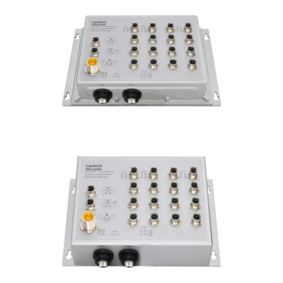
Chapter 2 Hardware Description In this paragraph, it will describe the Industrial switch’s hardware spec, port, cabling information, and wiring installation. 2.1 Physical Dimension Aluminum case. IP-67, 285 (W) x 201.4 (D) x 84.4 (H) mm Port description of IP-67 series switch... - Page 14 Aluminum case. IP-43, 273 (W) x 188.4(D) x 84.4 (H) mm **The description of interface of IP-43 model is the same as IP-67 series. 2.2 Package Content: Manual CD X1 Industrial Switch X1 Console cable X1...
-
Page 15: Ip Protection
2.3 IP Protection The IP Code, Ingress Protection Rating, sometimes also interpreted as International Protection Rating, classifies and rates the degree of protection provided against the intrusion (including body parts such as hands and fingers), dust, accidental contact, and water in mechanical casings and with electrical enclosures. It is published by the International Electrotechnical Commission (IEC) Solid particle protection The first digit indicates the level of protection that the enclosure provides against access... - Page 16 Liquid ingress protection The second digit indicates the level of protection that the enclosure provides against harmful ingress of water. Protected Level Testing for Details against — — protected Dripping Dripping water (vertically Test duration: 10 minutes water falling drops) shall have no Water equivalent to 1 mm harmful effect.
- Page 17 Powerful Water projected in powerful Test duration: at least water jets jets (12.5 mm nozzle) 3 minutes against the enclosure from Water volume: 100 litres per any direction shall have no minute harmful effects. Pressure: 100 kPa at distance of 3 m Immersion Ingress of water in harmful Test duration: 30 minutes...
-
Page 18: Led Indicators
2.4 LED Indicators The diagnostic LEDs that provide real-time information of system and optional status are located on the front panel of the industrial switch. The following table provides the description of the LED status and their meanings for the switch. Color Status Meaning... - Page 19 No device attached.
-
Page 20: Chapter 3 Hardware Installation
Chapter 3 Hardware Installation 3.1Hardware installation 3.1.1Unpack switch and check the accessory with packing list 3.1.2 Mount the switch on desired position 3.1.3 Connect the M23/M12 connector of power input. Voltage of Power Input Non-PoE model Standard model: (5-pin M12 The power input voltage can be from connector) 9.5V to 60VDC... - Page 21 72V model: The power input voltage can be from 50.4V to 90VDC to feed power on both 802.3af/at standardized devices. 110V model: The power input voltage can be from 43V to 137.5VDC to feed power on both 802.3af/at standardized devices. Make sure that the external power supply unit you use to provide the PoE voltage fulfils the following basic criteria: ...
- Page 22 electrically isolated from the housing. Note: With single power supply of the mains voltage, the device will report a power failure. You can disable this power fail event via web browser. Pin assignment of alarm relay A break in contact is reported via the relay contact : ...
- Page 23 Ground screw of IPES-5408T switch 3.1.5 Connect the M12 connector with RJ-45 data cable, ports are not used shall be caped that comes with the package to insulate the surrounding.
- Page 24 Pin assignment of M12 10/100Tx network connector 3.1.6 Check the status of LED, make sure the switch was in working status. Note: The protection class IP67/IP43 is only achieved when bolted together. The other components attaching to the system have to meet with the IP67/IP43 protection class in order to reach the whole system IP 67/IP43 protection.
-
Page 25: Chapter 4 Network Application
Chapter 4 Network Application 4.1 ITU G.8032 Scheme LANTECH G.8032 protocol is following ITU (International Telecommunication Unit) G.8032 v2 draft. The benefits of G.8032 are: 1. <50ms recovery time when failover 2. G.8032 has defined the protocol scheme, parameters, functions, test measures to be unified that the users can evaluate the possible network infrastructure without literally testing each brand in large scale. -
Page 26: Multiple Rings
4.3 Multiple Rings... -
Page 27: Dual Homing
4.4 Dual Homing 4.5 Chain... -
Page 29: Chapter 5 Console Management
Chapter 5 Console Management 5.1 Connecting to the Console Port The supplied cable which one end is M12 5-pole connector and the other end is RS- 232 connector. Attach the end of RS-232 connector to PC or terminal and the other end of M12 connector to the console port of the switch. - Page 30 The settings of communication parameters Having finished the parameter settings, click ‘OK’. When the blank screen shows up, press Enter key to have the login prompt appears. Key in ‘admin’ (default value) for both User name and Password (use Enter key to switch), then press Enter and the Main Menu of console management appears.
Need help?
Do you have a question about the IES-5216DF and is the answer not in the manual?
Questions and answers