Advertisement
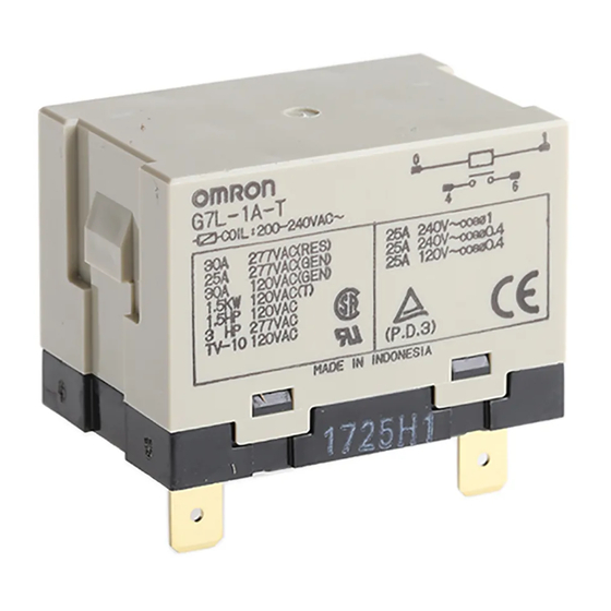
Power Relay
A High-capacity,
High-dielectric-strength Relay
Compatible with Momentary Voltage
Drops
No contact chattering for momentary voltage drops
up to 50% of rated voltage.
Wide-range AC-activated coil that handles 100 to
120 or 200 to 240 VAC at either 50 or 60 Hz.
Miniature hinge for maximum switching power,
particularly for inductive loads.
Flame-resistance materials (UL94V-0-qualifying)
used for all insulation material.
Quick-connect, screw, and PCB terminals, and DIN
track mounting available.
Ordering Information
Mounting type
E-bracket
E-bracket (with test button)
Upper bracket
Upper bracket
(with test button)
PCB mounting
Note: 1. When ordering, add the rated coil voltage to the model number.
Example: G7L-1A-T 12 VAC (~)
Contact form
Quick-connect
terminals
SPST-NO
G7L-1A-T
DPST-NO
G7L-2A-T
SPST-NO
G7L-1A-TJ
DPST-NO
G7L-2A-TJ
SPST-NO
G7L-1A-TUB
DPST-NO
G7L-2A-TUB
SPST-NO
G7L-1A-TUBJ
DPST-NO
G7L-2A-TUBJ
SPST-NO
---
DPST-NO
---
Rated coil voltage
Screw terminals
G7L-1A-B
---
G7L-2A-B
---
G7L-1A-BJ
---
G7L-2A-BJ
---
G7L-1A-BUB
---
G7L-2A-BUB
---
G7L-1A-BUBJ
---
G7L-2A-BUBJ
---
---
G7L-1A-P
---
G7L-2A-P
G7L
CE
R
PCB
terminals
1
Advertisement
Table of Contents

Related Manuals for Omron G7L


Summary of Contents for Omron G7L
- Page 1 G7L-2A-TUB G7L-2A-BUB Upper bracket SPST-NO G7L-1A-TUBJ G7L-1A-BUBJ (with test button) DPST-NO G7L-2A-TUBJ G7L-2A-BUBJ PCB mounting SPST-NO G7L-1A-P DPST-NO G7L-2A-P Note: 1. When ordering, add the rated coil voltage to the model number. Example: G7L-1A-T 12 VAC (~) Rated coil voltage...
-
Page 2: Application Examples
1. Contact Form 3. Mounting Construction 5. Rated Coil Voltage 1A: SPST-NO Blank: E-bracket AC: 12, 24, 50, 100 to 120, 200 to 240 2A: DPST-NO Upper bracket DC: 6, 12, 24, 48, 100 2. Terminal Shape 4. Special Functions... -
Page 3: Specifications
100 V 19 mA Note: 1. The rated current and coil resistance are measured at a coil temperature of 23#C with tolerances of +15%/--20% for AC rated current and $15% for DC coil resistance. 2. Performance characteristic data are measured at a coil temperature of 23#C. - Page 4 4,000 VAC min., 50/60 Hz for 1 min between coil and contacts 2,000 VAC, 50/60 Hz for 1 min between contacts of same polarity 2,000 VAC, 50/60 Hz for 1 min between contacts of different polarity (DPST-NO model) 10,000 V between coil and contact (with 1.2 x 50 's impulse wave)
- Page 5 20 FLA/120 LRA 120 VAC 20 FLA/120 LRA, 120 VAC 30 x 10 17 FLA/102 LRA, 265 VAC TV-8, 120 VAC 25 x 10 TÜV: File No. R9051158 (VDE 0435, IEC 255, IEC 950, EN60950) Model Contact Form Coil ratings Contact ratings Operations...
-
Page 6: Engineering Data
Engineering Data G7L-1A-T/G7L-1A-B Maximum Switching Power Life Expectancy AC resistive load AC inductive load (cos% = 0.4) 220 VAC resistive load 220 VAC inductive load (cos% = 0.4) Switching voltage (V) Switching current (A) G7L-2A-T/G7L-2A-B Maximum Switching Power Life Expectancy... - Page 7 Test Button G7L-2A-TJ with Test Button Quick-connect Terminals with DIN Track Mounting Adapter Note: 1. The DIN Track Mounting Adapter and DIN tracks are sold separately. 2. The DIN Track Mounting Adapter can be track-mounted or screw-mounted. G7L-1A-T P7LF-D...
- Page 8 51.5 max. 63 max. 55.5 max. 66.5 max. Quick-connect Terminals with Front-connecting Socket Note: 1. The Front-connecting Socket and DIN tracks are sold separately. 2. The Front-connecting Socket can be track-mounted or screw-mounted. G7L-1A-T Two, M3.5 screws Terminal Arrangement/ Mounting Holes...
- Page 9 Test Button 51.5 max. 61.5 max. 55.5 max. 65 max. Four, M4 screws for contact Quick-connect Terminals with Upper Bracket G7L-1A-TUB Mounting Holes Terminal Arrangement/ Internal Connections (Top View) Two, 4.5-dia. hole or M4 tapped holes G7L-2A-TUB...
- Page 10 Mounting Holes with Test Button Internal Connections (Top View) Two, 4.5-dia. hole or M4 tapped holes Screw Terminals with E-bracket Note: E-brackets are sold separately. G7L-1A-B Two, M3.5 screws Two, M4 screws for coil for contact Mounting Holes Terminal Arrangement/...
- Page 11 Screw Terminals with DIN Track Mounting Adapter Note: 1. The DIN Track Mounting Adapter and DIN tracks are sold separately. 2. The DIN Track Mounting Adapter can be track-mounted or screw-mounted. G7L-1A-B P7LF-D Terminal Arrangement/ Mounting Holes PFP-jN Internal Connections...
- Page 12 G7L-2A-BUBJ with Test Button Two, M3.5 screws for coil Four, M4 screws for contact Terminal Arrangement/ Internal Connections (Top View) PCB Terminals with PCB Mounting G7L-1A-P Mounting Holes (Bottom View) Terminal Arrangement/ Internal Connections (Top View) G7L-2A-P Mounting Holes (Bottom View)
- Page 13 46 max. 40$0.1 55.5 max. P7LF-C Cover 34.5 max. Put the P7LF-C cover onto the terminals in order 50.5 max. to protect the user from electric shock. 6 max. Internal Coil Circuit DC Operating Coil AC Operating Coil...
-
Page 14: Installation
(M4) should be 20 A or less according to jet stan- dard (electrical appliance and material control law of Japan). ALL DIMENSIONS SHOWN ARE IN MILLIMETERS. To convert millimeters into inches, multiply by 0.03937. To convert grams into ounces, multiply by 0.03527. Cat. No. J055-E1-3A...
Need help?
Do you have a question about the G7L and is the answer not in the manual?
Questions and answers