Table of Contents
Advertisement
Quick Links
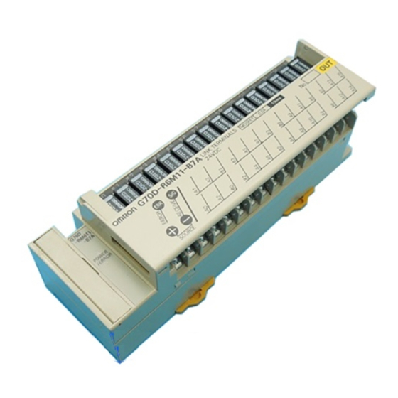
Link Terminals with 16 Relay Outputs
Ultra Miniature Link Terminal with B7A
Communications Functions and 16
Output Points
Equipped with B7A communications functions and
enables wiring reductions in B7A connections
(except for high-speed models).
Power relay (G6D) models and power MOS FET
relay (G3DZ) models available.
Compact dimensions: 156
H).
The load is connected directly to the terminal block
without the need for a relay terminal.
Signal status can be confirmed at a glance with
Operation indicators.
Incorporates surge absorbing diode.
Equipped with Relay Removal Tool.
Supports either screw mounting or DIN track
Ordering Information
Product List
Classification
Number of I/O
Relay output
e ay ou u
16 (SPST-NO
6 (S S
Power MOS FET
o e
OS
relay output
l
t
t
Note: 1. Not connectable to high-speed B7A models.
2. When an error occurs, the status of outputs just before the error occurred is maintained.
3. When an error occurs, all the outputs are turned OFF.
Characteristics
Communications Specifications
Communications method
Transmission distance
(see note)
I/O delay time
Note: Separate power supplies are required for inputs and out-
puts.
44
51
51 mm (W
Rated voltage
points
O
16)
6)
24 VDC
C
Unidirectional, time-division
multiplex
500 m max.
Typical: 19.2 ms; 31 ms max.
D
I/O delay time
Normal (typical:
o
a ( y ca
HOLD (See note 2.)
19.2 ms)
19 2
)
LOAD OFF (See note
(See note 1.)
3.)
HOLD (See note 2.)
LOAD OFF (See note
3.)
G70D-B7A
Error processing
G70D-R6R11-B7A
G70D-R6R31-B7A
G70D-R6M11-B7A
G70D-R6M31-B7A
Model
Advertisement
Table of Contents

Subscribe to Our Youtube Channel
Related Manuals for Omron G70D B7A Series


Summary of Contents for Omron G70D B7A Series
- Page 1 Link Terminals with 16 Relay Outputs G70D-B7A Ultra Miniature Link Terminal with B7A Communications Functions and 16 Output Points Equipped with B7A communications functions and enables wiring reductions in B7A connections (except for high-speed models). Power relay (G6D) models and power MOS FET relay (G3DZ) models available.
- Page 2 G70D-B7A G70D-B7A General G70D-R6R 1-B7A (Relay Outputs) Item Specification Contacts 16 SPST-NO contacts Contact mechanism Single Contact material Agco Contact resistance (See note 1.) 100 mΩ max. Operating time 10 ms max. Release time 10 ms max. Maximum switching frequency g eque cy Mechanical 18,000 operations/hour...
- Page 3 G70D-B7A G70D-B7A G70D-R6M 1-B7A (Power MOS FET Relay Outputs) Item Specification Contacts 16 SPST-NO contacts Isolation method Photocoupler Operating time 6 ms max. Release time 10 ms max. 2.4 Ω max. Output ON resistance 10 µA max. (at 125 VDC) Current leakage when the relay is closed Insulation resistance 100 MΩ...
- Page 4 G70D-B7A G70D-B7A Contact Ratings (for each G6D Relay) Load Resistive load (cosφ = 1) Rated load 250 VAC 3 A, 30 VDC 3 A Rated carry current Maximum switching voltage 250 VAC, 30 VDC Maximum switching current Maximum switching capacity 750 VA, 90 W (reference value) Minimum permissible load...
- Page 5 G70D-B7A G70D-B7A G3DZ-2R6PL (Power MOS FET Relay Mounted to G70D-R6M 1-B7A) Load Current vs. Ambient Temperature Inrush Current Resistivity (Non-repetitive) (The value will be less than half for repetitive inrush currents.) Energizing time (ms) Ambient temperature ( C) Note: The above graph shows the characteris- Note: The above graph shows the characteris- tics for the Relay when it is mounted to tics for the Relay when it is mounted to...
- Page 6 G70D-B7A G70D-B7A Dimensions Note: All units are in millimeters unless otherwise indicated. G70D-R6 1-B7A 156 max. 51 max. Thirty-two, M3 terminals 51 max. Installation Internal Circuits G70D-R6R11-B7A, G70D-R6M11-B7A G70D-R6R31-B7A, G70D-R6M31-B7A Relay driver Relay driver Relay driver DC-DC converter Relay driver (See note.) Note: The above diagram is for G70D-R6R 1-B7A models (G6D-mounting).
- Page 7 G70D-B7A G70D-B7A Precautions General Replacing Relays Do not mount or dismount relays with the power supplied. Doing so Electric Shock may result in electric shock or malfunction. Do not touch charged parts of relay terminals or socket terminals When replacing relays, use the yellow Relay Removal Tool at the while power is supplied.
Need help?
Do you have a question about the G70D B7A Series and is the answer not in the manual?
Questions and answers