Table of Contents
Advertisement
Quick Links
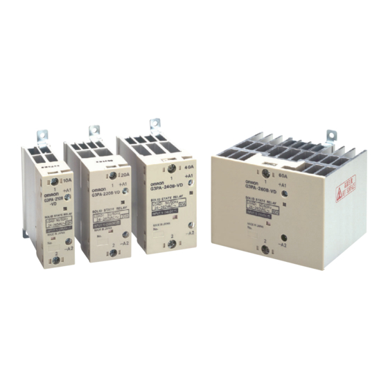
Solid State Relays
G3PA
Extremely Thin Relays Integrated with Heat
Sinks
• Downsizing achieved through optimum design of heat sink.
• Mounting possible via screws or via DIN track.
• Close mounting possible for linking terminals. (Except for G3PA-
260B-VD and G3PA-450B-VD-2.)
• Applicable with 3-phase loads.
• Replaceable power element cartridges.
• Comply with VDE 0160 (finger protection), with a dielectric
strength of 4,000 V between input and load.
• Certified by UL, CSA, and VDE (reinforced insulation).
Refer to Safety Precautions for All Solid State
Relays.
Model Number Structure
■ Model Number Legend
G3PA-@@@@-@-@
1
2 3 4 5
6
7
1. Basic Model Name
G3PA: Solid State Relay
2. Rated Load Power Supply Voltage
2:
200 VAC
4:
400 VAC
3. Rated Load Current
10:
10 A
20:
20 A
30:
30 A
40:
40 A
50:
50 A
60:
60 A
4. Terminal Type
B:
Screw terminals
5. Zero Cross Function
Blank: Equipped with zero cross function
L:
Not equipped with zero cross function
6. Certification
VD:
Certified by UL, CSA, and VDE
7. Special Specifications
Blank: Standard models
2:
480-V models
CSM_G3PA_DS_E_2_1
1
Advertisement
Table of Contents

Related Manuals for Omron G3PA-260B-VD


Summary of Contents for Omron G3PA-260B-VD
- Page 1 Solid State Relays G3PA CSM_G3PA_DS_E_2_1 Extremely Thin Relays Integrated with Heat Sinks • Downsizing achieved through optimum design of heat sink. • Mounting possible via screws or via DIN track. • Close mounting possible for linking terminals. (Except for G3PA- 260B-VD and G3PA-450B-VD-2.) •...
-
Page 2: Ordering Information
40 A G32A-A40-VD DC5-24 G3PA-240B-VD DC5-24 G32A-A40L-VD DC5-24 G3PA-240BL-VD DC5-24 G32A-A40-VD AC24 G3PA-240B-VD AC24 60 A G32A-A60-VD DC5-24 G3PA-260B-VD DC5-24 G32A-A60L-VD DC5-24 G3PA-260BL-VD DC5-24 G32A-A60-VD AC24 G3PA-260B-VD AC24 20 A 150 to 440 VAC G32A-A420-VD DC12-24 G3PA-420B-VD DC12-24 30 A... -
Page 3: Specifications
G3PA-210B-VD 5 to 24 VDC 4 to 30 VDC 7 mA max. 4 VDC max. 1 VDC min. G3PA-220B-VD G3PA-240B-VD G3PA-260B-VD G3PA-210BL-VD 5 to 24 VDC 4 to 30 VDC 20 mA max. 4 VDC max. 1 VDC min. G3PA-220BL-VD... - Page 4 G3PA ■ Characteristics Item G3PA- G3PA- G3PA- G3PA- G3PA- G3PA- G3PA- G3PA- G3PA- 210B(L)-VD 220B(L)-VD 240B(L)-VD 260B(L)-VD 420B-VD 420B-VD-2 430B-VD 430B-VD-2 450B-VD-2 Operate time 1/2 of load power source cycle + 1 ms max. (DC Input, -B models) 1 1/2 of load power source cycle + 1 ms max. (AC Input) 1 ms max.
-
Page 5: Operation
G3PA Operation ■ Replacement Parts G32A-A Power Device Cartridge The G32A-A Power Device Cartridge (a Triac Unit) can be replaced with a new one. When the temperature indicator has changed from pink to red, the triac circuitry may have malfunctioned possibly by an excessive flow of current, in which case, dismount the damaged cartridge for replacement. The damaged cartridge can be replaced with a new one without disconnecting the wires from the G3PA. - Page 6 G3PA ■ Replacement Procedure G32A-A10(L)-VD/G32A-A20(L)-VD/G32-A420-VD(-2) To remove or replace the Power Device Cartridge, use the special tool provided with it for extraction. Extraction Follow the procedures below to dismount the Power Device Cartridge from the G3PA. 1. Switch off the power. 2.
- Page 7 G3PA 3. Insert the cartridge into the opening of the G3PA so that side A 4. Tighten the screws on both the corners with a tightening torque of and side B are even. 0.59 to 0.78 N·m. 5. Tighten the screws on both the sides with a tightening torque of 0.59 to 0.78 N·m.
-
Page 8: Engineering Data
G3PA Engineering Data Load Current vs. Ambient Temperature Vertical Mounting Panel Ground G3PA-210B(L)-VD, G3PA-220B(L)-VD G3PA-240B(L)-VD G3PA-260B(L)-VD G3PA-220B(L)-VD G3PA-210B(L)-VD Ambient temperature (°C) Ambient temperature (°C) Ambient temperature (°C) G3PA-220B-VD For single mounting, the ambient temperature is 80°C. The rated current is 5 A. For close mounting of two or three SSRs, limit the load current to 90% or less. -
Page 9: Horizontal Mounting
G3PA Input Voltage vs. Input Current G3PA-2@0B-VD G3PA-4@0-VD, G3PA-4@-VD-2 T = 25°C Ta = 25°C Input current Input current Input impedance Input impedance Input voltage (V) Input voltage (V) Horizontal Mounting Panel Ground G3PA-210B(L)-VD, G3PA-220B(L)-VD G3PA-240B(L)-VD G3PA-260B(L)-VD G3PA-220B(L)-VD G3PA-210B(L)-VD −30 −20 Ambient temperature (°C) Ambient temperature (°C) - Page 10 G3PA Close Mounting (Up to Three) Panel Ground DIN track G3PA-210B(L)-VD, G3PA-220B(L)-VD G3PA-240B(L)-VD G3PA-260B(L)-VD G3PA-220B-VD G3PA-210B-VD Ambient temperature (°C) Ambient temperature (°C) Ambient temperature (°C) G3PA-420B-VD, G3PA-420B-VD-2 G3PA-430B-VD, G3PA-430B-VD-2 −30 −30 Ambient temperature (°C) Ambient temperature (°C) G3PA-450B-VD-2 Ambient temperature (°C)
- Page 11 G3PA One Cycle Surge Current: Non-repetitive Note: Keep the inrush current to half the rated value if it occurs repetitively. G3PA-210B(L)-VD G3PA-220B(L)-VD, G3PA-420B-VD, G3PA-240B(L)-VD/260B(L)-VD, G3PA-420B-VD-2 G3PA-430B-VD, G3PA-430B-VD-2, G3PA-450B-VD-2 Energized time (ms) Energized time (ms) Energized time (ms)
- Page 12 G3PA Dimensions Note: All units are in millimeters unless otherwise indicated. G3PA-210B(L)-VD With Terminal Without Terminal Mounting Terminal Cover Cover Holes Arrangement/ 4.6 dia. Two, M4 Internal Connections Linking terminal B1 Two, 4.5 dia. or M4 holes Two, M3.5 Linking terminal B2 4.6 x 5.6 elliptical hole...
- Page 13 G3PA G3PA-260B(L)-VD With Terminal Without Terminal G3PA-450B-VD-2 Cover Terminal Arrangement/ Cover Mounting Holes Internal Connections 4.6 dia. Two, M5 Two, M3.5 Two, 4.5 dia. or M4 holes G3PA-260B G3PA-450B -VD-2 − − 4.6 x 5.6 elliptical hole 110 max. 100 max. G3PA-420B-VD, G3PA-420B-VD-2 Without Terminal With Terminal...
-
Page 14: Safety Precautions
G3PA Safety Precautions ■ Precautions for Correct Use Load Please observe the following precautions to prevent failure to Load power Input operate, malfunction, or undesirable effect on product performance. supply Load Connection When attaching a heat sink to the G3PA-(VD), in order to facilitate heat dissipation, apply silicone grease or equivalent heat-conductive For an AC load, use a power supply rated at 50 or 60 Hz. -
Page 15: Close Mounting
G3PA Close Mounting A heat exchanger, if used, should be located in front of the SSR Units to ensure the efficiency of the heat exchanger. SSR Mounting Pitch Please reduce the ambient temperature of SSRs. The rated load current of an SSR is measured at an ambient Panel Mounting (At a rated ambient temperature of 40°C). - Page 16 Warranty and Limitations of Liability WARRANTY OMRON's exclusive warranty is that the products are free from defects in materials and workmanship for a period of one year (or other period if specified) from date of sale by OMRON. OMRON MAKES NO WARRANTY OR REPRESENTATION, EXPRESS OR IMPLIED, REGARDING NON-INFRINGEMENT, MERCHANTABILITY, OR FITNESS FOR PARTICULAR PURPOSE OF THE PRODUCTS.
Need help?
Do you have a question about the G3PA-260B-VD and is the answer not in the manual?
Questions and answers