Table of Contents
Advertisement
Quick Links
See also:
Manual
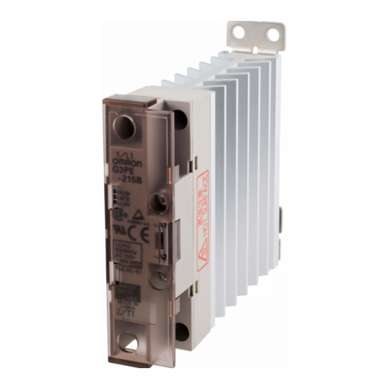
Single-phase Solid State Relays for Heaters
G3PE
Slim Profile Industrial SSR with Heatsink
ideal for heater applications.
• Snubber circuit provides excellent short-term surge
absorption.
• 15A and 25A models have slim 22.5mm width.
• Zero cross or "fast turn on" models.
• DIN track or panel mounting possible.
• LED indicator standard on all single phase models.
• UL, CSA and TÜV approved
• RoHS compliant.
Refer to Safety Precautions
Ordering Information
■ List of Models
Number of
Isolation
phases
method
Phototriac
Single-phase
coupler
* The applicable load current depends on the ambient temperature. For details, refer to Load Current vs. Ambient Temperature in the Engineering
Data section.
.
Operation
Rated input
indicator
voltage
Yes (yellow)
12 to 24 VDC
Single-phase Solid State Relays for Heaters
Zero cross
Applicable load *
function
15 A, 100 to 240 VAC G3PE-215B DC12-24
25 A, 100 to 240 VAC G3PE-225B DC12-24
Yes
35 A, 100 to 240 VAC G3PE-235B DC12-24
45 A, 100 to 240 VAC G3PE-245B DC12-24
15 A, 100 to 240 VAC G3PE-215BL DC12-24
25 A, 100 to 240 VAC G3PE-225BL DC12-24
No
35 A, 100 to 240 VAC G3PE-235BL DC12-24
45 A, 100 to 240 VAC G3PE-245BL DC12-24
Model
G3PE
445
Advertisement
Table of Contents

Related Manuals for Omron G3PE Series


Summary of Contents for Omron G3PE Series
- Page 1 Single-phase Solid State Relays for Heaters G3PE Slim Profile Industrial SSR with Heatsink ideal for heater applications. • Snubber circuit provides excellent short-term surge absorption. • 15A and 25A models have slim 22.5mm width. • Zero cross or “fast turn on” models. •...
-
Page 2: Specifications
Specifications ■ Ratings Input (at an Ambient Temperature of 25°C) Voltage level Item Rated voltage Operating voltage range Rated input current Model Must operate voltage Must release voltage G3PE-@@@B 12 to 24 VDC 9.6 to 30 VDC 7 mA max. 9.6 VDC max. -
Page 3: Engineering Data
Engineering Data Input Voltage vs. Input Impedance and Input Voltage vs. Input Current G3PE-2@@B G3PE-2@@BL Ta = 25°C Ta = 25°C Input current Input current Input impedance Input impedance Input voltage (V) Input voltage (V) Load Current vs. Ambient Temperature G3PE-215B(L), G3PE-225B(L) G3PE-235B(L), G3PE-245B(L) G3PE-245B(L) - Page 4 Close Mounting (3 or 8 SSRs) G3PE-215B(L) G3PE-225B(L) G3PE-235B(L) G3PE-245B(L) 3 Relays 3 Relays 3 Relays 3 Relays 8 Relays 8 Relays 8 Relays 8 Relays −40 −20 −40 −20 80 100 −40 −20 −40 −20 80 100 80 100 80 100 Ambient temperature (°C) Ambient temperature (°C)
-
Page 5: Solid State Relays
Dimensions Note: All units are in millimeters unless otherwise indicated. Solid State Relays G3PE-215B(L) Two, ±0.2 4.6 dia. G3PE-225B(L) Two, M4 100 max. ±0.2 Two, M3.5 4.6 × 5.6 elliptical hole 22.5 max. Note: Without terminal cover. Note: With terminal cover. Mounting Holes Terminal Arrangement/Internal Circuit Diagram ±0.3... -
Page 6: Safety Precautions
Using the G3PE mounted in wood or other material with a high heat resistance may result in fire or OMRON constantly strives to improve quality and reliability. burning due to heat generated by the G3PE. -
Page 7: Precautions For Correct Use
Wiring Precautions for Correct Use • When using crimp terminals, refer to the terminal clearances The SSR in operation may cause an unexpected accident. shown below. Therefore it is necessary to test the SSR under the variety of Output Terminal Section for Three-phase Models conditions that are possible. -
Page 8: Emc Connection
EMC Connection Mounting to Control Panel Make EMC connections according to the following figure. The G3PE is heavy. Firmly mount the DIN track and secure both ends with End Plates for DIN-track-mounting models. When mount- • Connect a capacitor to the load power supply. ing the G3PE directly to a panel, firmly secure it to the panel. - Page 9 Relationship between the G3PE and Ducts or Other Objects Blocking Airflow Incorrect Example Countermeasure 1 Countermeasure 2 Duct or other object 50 mm max. Duct blocking airflow (No more than 1/2 the SSR depth is recom- Airflow mended.) Duct Vertical Base Direction Duct...
- Page 10 All sales are subject to Omron Electronic Components LLC standard terms and conditions of sale, which can be found at http://www.components.omron.com/components/web/webfiles.nsf/sales_terms.html ALL DIMENSIONS SHOWN ARE IN MILLIMETERS. To convert millimeters into inches, multiply by 0.03937. To convert grams into ounces, multiply by 0.03527.
Need help?
Do you have a question about the G3PE Series and is the answer not in the manual?
Questions and answers