Advertisement
Quick Links
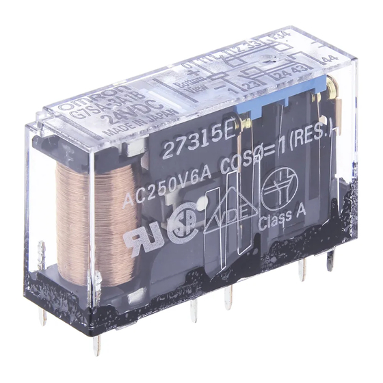
Safety Relay
Slim Safety Relays Conforming to EN
Standards
The forcibly guided contact in the G7SA assures
safe operation (EN50205 Class A, approved by
VDE.)
Ideal for use in safety circuits in press machinery,
machine tools, and other production machinery.
Four-pole and six-pole Relays are available.
The Relay's terminal arrangement simplifies PWB
pattern design.
Reinforced insulation between inputs and outputs.
Reinforced insulation between some poles.
UL, CSA approval.
CE marking.
Note: Be sure to refer to the Precautions on page 131.
Ordering Information
Safety Relays
Type
Standard
S a da d
Flux-tight
u
Safety Relay Sockets
Track-mounting
ac
ou
g
Track mounting and screw mounting
ac
possible
ibl
Back-mounting
ac
ou
g
PCB terminals
C
e
Model Number Legend
G7SA-jAjB
1
2
1.
NO Contact Poles
2:
DPST-NO
3:
3PST-NO
4:
4PST-NO
5:
5PST-NO
2.
NC Contact Poles
1:
SPST-NC
2:
DPST-NC
3:
3PST-NC
132
Sealing
Poles
g
4 poles
o es
6 o es
6 poles
Type
ou
g a d sc e
ou
g
a s
Contacts
Rated voltage
24 VDC
3PST-NO, SPST-NC
DPST-NO, DPST-NC
5PST-NO, SPST-NC
4PST-NO, DPST-NC
3PST-NO, 3PST-NC
LED indicator
Poles
No
o
4 poles
6 poles
Yes
es
4 poles
6 poles
No
o
4 poles
6 poles
G7SA
X
RC
VDE
Model
C
G7SA-3A1B
G7SA-2A2B
G7SA-5A1B
G7SA-4A2B
G7SA-3A3B
Rated
Model
voltage
---
P7SA-10F
P7SA-14F
24 VDC
C
P7SA-10F-ND
P7SA-14F-ND
---
P7SA-10P
P7SA-14P
Advertisement

Related Manuals for Omron G7SA


Summary of Contents for Omron G7SA
- Page 1 The Relay’s terminal arrangement simplifies PWB pattern design. Reinforced insulation between inputs and outputs. Reinforced insulation between some poles. UL, CSA approval. CE marking. Note: Be sure to refer to the Precautions on page 131. Ordering Information Safety Relays Type Sealing Poles...
-
Page 2: Specifications
100 M min. (see note 2) Note: 1. If the P7SA-1jF is used between 55 and 85 C, reduce the continuous current (from 6A) by 0.1 A for every degree. 2. Measurement conditions: Measurement of the same points as for the dielectric strength at 500 VDC. -
Page 3: Safety Relays
5. Min. permissible load is for a switching frequency of 300 operations/min. 6. When operating at a temperature between 70 C and 85 C, reduce the rated carry current (6 A at 70 C or less) by 0.1 A for each degree above 70 C. - Page 4 Two, 4 dia. or M3.5 72 max. indicator 9 max. 4 dia. Note: The socket is shown with the finger cover removed. Note: Only the -ND Sockets have LED indicators. Track-mounting Socket Terminal Arrangement/Internal Connection Diagram (Top View) P7SA-14F, P7SA-14F-ND G7SA-5A1B G7SA-4A2B...
- Page 5 Three, 3.2 dia. (for M3 tapping screws) Fourteen, 1.1 dia. 41.5 max. G7SA-4A2B Mounted Three, 2.6 dia. (for M3 tapping screws) G7SA-3A3B Mounted Note: Terminals 23-24, 33-34, 43-44, 53-54, and 63-64 are normally open. Terminals 11-12, 21-22, and 31-32 are normally closed.
- Page 6 Wire the terminals correctly with no mistakes in coil polarity, other- wise the G7SA will not operate. ALL DIMENSIONS SHOWN ARE IN MILLIMETERS. To convert millimeters into inches, multiply by 0.03937. To convert grams into ounces, multiply by 0.03527. Cat. No. J120-E1-1A...
Need help?
Do you have a question about the G7SA and is the answer not in the manual?
Questions and answers