Table of Contents
Advertisement
Quick Links
ITEM #5519818
MODEL #AUR52MBK5LR
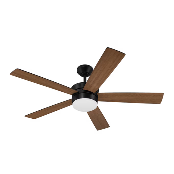
AURORA LED CEILING FAN
Español p. 22
ATTACH YOUR RECEIPT HERE
ADJUNTE SU RECIBO AQUÍ
Purchase Date
4007498
Questions, problems, missing parts? Before returning to your retailer, call our customer service
department at 800-527-1292,
8:30 a.m. - 5 p.m., CST, Monday - Friday.
1
Advertisement
Table of Contents

Subscribe to Our Youtube Channel
Related Manuals for Litex Industries AURORA AUR52MBK5LR


Summary of Contents for Litex Industries AURORA AUR52MBK5LR
- Page 1 ITEM #5519818 MODEL #AUR52MBK5LR AURORA LED CEILING FAN Español p. 22 ATTACH YOUR RECEIPT HERE ADJUNTE SU RECIBO AQUÍ Purchase Date 4007498 Questions, problems, missing parts? Before returning to your retailer, call our customer service department at 800-527-1292, 8:30 a.m. - 5 p.m., CST, Monday - Friday.
-
Page 2: Table Of Contents
(1) this device may not cause harmful interference, (2) this device must accept any interference received, including interference that may cause undesired operation. Distributed by: Litex Industries Inc., P.O. Box 535639, Grand Prairie, TX, 75050; 800-527-1292 NOTE: Dimmable to 10%. -
Page 3: Safety Information
SAFETY INFORMATION READ AND SAVE THESE INSTRUCTIONS Please read and understand this entire manual before attempting to assemble, install or operate the product. Review the accompanying assembly diagrams. • Do not discard fan carton or foam inserts. Should this fan need to be returned to the factory for repairs, it must be shipped in its original packaging to ensure proper protection against damage that might exceed the initial cause for return. - Page 4 SAFETY INFORMATION WARNING To reduce the risk of fire or electrical shock, do not use the fan with any solid state speed control device or control fan speed with a full range dimmer switch. To reduce the risk of fire, electrical shock or personal injury, do not bend the blade arms when installing them, balancing the blades or cleaning the fan.
-
Page 5: Package Contents
PACKAGE CONTENTS QUANTITY PART DESCRIPTION PART DESCRIPTION QUANTITY Downrod Motor Plate Screw Mounting Bracket (preassembled) (preassembled) Fitter Plate Screw Canopy (preassembled) Yoke Cover Canopy Mounting Screw/lock washer (preassembled) Motor Housing Remote Control Receiver Blade Remote Pack Fitter Plate LED Light Kit Shade IMPORTANT REMINDER: You must use the Pin (preassembled) -
Page 6: Hardware Contents
HARDWARE CONTENTS (shown actual size) Blade Fiber Wire Screw Washer Connector Qty. 15 Qty. 15 Qty. 4 + 1 extra + 1 extra PREPARATION Before beginning assembly of product, make sure all parts are present. Place motor on carpet or on foam to avoid damage to finish. - Page 7 INITIAL INSTALLATION 2. Determine mounting method to use. A. Downrod mount (standard or angled ceiling). 20° max. B. Closemount (standard ceiling only). IMPORTANT: If using the angle mount, check to make sure the ceiling angle is not steeper than 20°. *Helpful Hint: Downrod-style mounting is best suited for ceilings 8 ft.
-
Page 8: Downrod-Style Fan Mounting
INITIAL INSTALLATION 5. Remove all three preassembled motor stabilization pieces from motor housing (E). The motor stabilization pieces may be discarded at this time. For DOWNROD-STYLE FAN MOUNTING, proceed to Step 1 below. For CLOSEMOUNT-STYLE FAN MOUNTING, skip to page 10. Motor Stabilization Piece... - Page 9 DOWNROD-STYLE FAN MOUNTING 3. Slip downrod (A) into yoke, align holes and re-install pin (J) and clip (K). Tighten downrod set screws and then tighten nut. Set Screw and Nut Depending on the length of downrod you use, you may need to cut the lead wires back to simplify the wiring.
-
Page 10: Closemount-Style Fan Mounting
DOWNROD-STYLE FAN MOUNTING Install hanging ball of downrod (A) into opening of mounting bracket (B). Align the slot in hanging ball with the tab in mounting bracket (B). DANGER: Failure to align slot in hanging ball with the tab in mounting bracket (B) may result in serious injury or death. - Page 11 CLOSEMOUNT-STYLE FAN MOUNTING 3. Pull wires up through hole in the middle of the Screw canopy (C) and attach canopy (C) to motor Lock Washer housing (E) using the three screws/lock washers previously removed. Temporarily hang fan on the tab on the mounting bracket (B) using one of the non-slotted holes in the canopy (C).
-
Page 12: Wiring
WIRING WARNING: To reduce the risk of fire, electrical shock or personal injury, wire connectors provided with this fan are designed to accept only one 12-gauge house wire and two lead wires from the fan. If your house wire is larger than 12-gauge or there is more than one house wire to connect to the corresponding fan lead wires, consult an electrician for the proper size wire connectors to use. -
Page 13: Final Installation
WIRING Wrap electrical tape (not included) around each individual wire connector (CC) down to the wire. WARNING: Make sure no bare wire or wire strands are visible after making connections. Place GREEN and WHITE connections on opposite side of the outlet box from the BLACK and BLUE (if applicable) connections. - Page 14 FINAL INSTALLATION DANGER: To reduce the risk of serious bodily injury, DO NOT use power tools to assemble the blades (F). If screws are overtightened, blades (F) may crack and break. Insert the blade (F) through the slot on the band of the motor housing (E).
- Page 15 FINAL INSTALLATION 5. Connect female plug from motor housing (E) to male plug from LED light kit (H), matching up the colors on the plugs for correct fit. Make sure plugs connect tightly. male plug female plug 6. Carefully arrange wiring within the fitter plate (G) to ensure wires do not get pinched when attaching the LED light kit (H).
-
Page 16: Operating Instructions
OPERATING INSTRUCTIONS CAUTION: The remote control transmitter can be programmed to multiple receivers or fans. If this is not desired, turn wall switch off to any other programmable receiver or fan. FCC Compliance Notice for Remote Control CAUTION: Changes or modifications not approved by the party responsible for compliance could void the user's authority to operate the equipment. - Page 17 OPERATING INSTRUCTIONS 2. NOTE: Remove protective covering from front of remote control transmitter and discard. If fan and/or remote control fail(s) to operate or you have purchased a new remote control transmitter, make sure to turn the power off first. Restore electrical power.
- Page 18 OPERATING INSTRUCTIONS 4. Use the fan reverse switch located on the top part of the motor housing (E) to optimize the fan for seasonal performance. A ceiling fan will allow you to raise your thermostat setting in summer and lower Reverse Switch your thermostat setting in winter without feeling a...
-
Page 19: Care And Maintenance
CARE AND MAINTENANCE At least twice each year, check canopy mounting screws (N) and then tighten all screws on the fan. Clean motor housing (E) with only a soft brush or lint-free cloth to avoid scratching the finish. Clean blades (F) with a lint-free cloth. IMPORTANT: Shut off main power supply before beginning any maintenance. -
Page 20: Limited Lifetime Warranty
TROUBLESHOOTING PROBLEM POSSIBLE CAUSE CORRECTIVE ACTION 1. Blades are loose. Fan operates but 2. Cracked blade. 1. Check wires in outlet box and, if light fails 3. Full range dimmer switch. necessary, re-wire according to instructions on page 12. 4. Fan is new. 2. -
Page 21: Replacement Parts List
REPLACEMENT PARTS LIST For replacement parts, call our customer service department at 800-527-1292, 8:30 a.m. - 5 p.m., CST, Monday - Friday. PART DESCRIPTION PART # Downrod 5519818-A Mounting Bracket 5519818-B Canopy 5519818-C Blade 5519818-F Printed in China DRLI2311...
Need help?
Do you have a question about the AURORA AUR52MBK5LR and is the answer not in the manual?
Questions and answers