Table of Contents
Advertisement
Quick Links
Federal regulations require ceiling fans
with light kits manufactured or imported
after January 1, 2009, to limit total
wattage consumed by the light kit to
190W.
Therefore, this fan is equipped
with a wattage limiting device.
Installation Guide
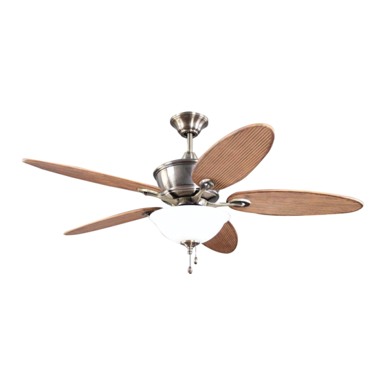
For Model:
E-CGL52CB5C1
For
Damp Location
E192641
net weight of fan: 24.03 lb (10.9 kg)
READ THESE INSTRUCTIONS AND
SAVE THEM FOR FUTURE USE
Table of Contents:
Safety Tips. pg. 1
Unpacking Your Fan. pg. 2
Parts Inventory. pg. 2
Installation Preparation. pg. 3
Hanging Bracket Installation. pg. 3
Fan Assembly. pgs. 4 - 5
Wiring. pg. 5
Canopy Assembly. pg. 6
Blade Assembly. pg. 6
Testing Your Fan. pg. 8
Troubleshooting. pg. 9
Parts Replacement. pg. 9
Warranty. pg. 9
PRINTED IN CHINA
Advertisement
Table of Contents

Subscribe to Our Youtube Channel
Related Manuals for Litex Industries E-CGL52CB5C1


Summary of Contents for Litex Industries E-CGL52CB5C1
-
Page 1: Table Of Contents
190W. Therefore, this fan is equipped with a wattage limiting device. Installation Guide For Model: E-CGL52CB5C1 Table of Contents: Safety Tips. pg. 1 Unpacking Your Fan. pg. 2 Parts Inventory. pg. 2 Installation Preparation. pg. 3 Hanging Bracket Installation. -
Page 2: Safety Tips
SAFETY TIPS. WARNING: To reduce the risk of electrical shock, turn off the electricity to the fan at the main fuse box or circuit panel before you begin the fan installation or before servicing the fan or installing accessories. READ ALL INSTRUCTIONS AND SAFETY INFORMATION CAREFULLY BEFORE INSTALLING YOUR FAN AND SAVE THESE INSTRUCTIONS. -
Page 3: Unpacking Your Fan
1. Unpacking Your Fan. Carefully open the packaging. Remove items from Styrofoam inserts. Remove motor housing and place on carpet or Styrofoam to avoid damage to finish. Do not discard fan carton or Styrofoam inserts should this fan need to be returned for repairs. -
Page 4: Installation Preparation
3. Installation Preparation. blade edge To prevent personal injury and damage, ensure that the hanging location allows the blades a 7 feet inches (2.13m) (76cm) clearance of 7 ft. (2.13m) from the floor and 30in. (76 cm) from any wall or obstruction. This fan is suitable for room sizes up to 400 12ft. -
Page 5: Fan Assembly. Pgs
5. Fan Assembly. set screw hole If you wish to extend the hanging length of your set screw fan, you must remove the hanging ball from the stop pin downrod provided to use with an extended downrod (sold separately). [If you wish to use the downrod provided, please proceed to instructions following the dotted line below.] hanging ball... -
Page 6: Wiring
5. Fan Assembly. (cont.) With the hanging bracket secured to the outlet box and able to support the fan, you are now ready to hang your fan. Grab the fan firmly with two hands. Slide downrod through opening in hanging bracket and let hanging ball rest on the hanging bracket. -
Page 7: Canopy Assembly
7. Canopy Assembly. Locate 2 screws on underside of hanging bracket hanging bracket and remove screw closest to the open end of the hanging bracket. Partially loosen the other screw. Lift canopy to hanging bracket. Place rounded screw screw part of slotted hole in canopy over loosened screw in hanging bracket and push up. -
Page 8: Light Kit Assembly (Optional). Pgs
9. Light Kit Assembly (Optional). Remove 1 screw from fitter plate (on underside of motor) and loosen the other 2 screws. Align slotted holes in switch housing plate with loosened screws in motor housing fitter plate, allowing male plug from motor housing to come through hole in middle of switch housing plate. -
Page 9: Testing Your Fan
9. Light Kit Assembly (Optional). (cont). If you wish to use the fan WITHOUT the light kit, locate wires in switch housing (at top of light kit fitter) labeled FOR LIGHT. Gently pull molex connections apart in order to BLACK disconnect these wires. -
Page 10: Troubleshooting
Service at 1-800-527-1292 to arrange for return of fan. 2. Verify that reverse switch is set completely in either Return fan, shipping prepaid, to Litex Industries, Ltd. We will direction. repair or ship you a replacement fan, and we will pay the 3.
Need help?
Do you have a question about the E-CGL52CB5C1 and is the answer not in the manual?
Questions and answers