Table of Contents
Advertisement
Quick Links
Express Assembly
No Tools Required
ATTACH YOUR RECEIPT HERE
Purchase Date
Questions, problems, missing parts? Before returning to your retailer, call our customer
service department at
1-800-527-1292, 8:30 a.m. - 5 p.m., CST, Monday - Friday
1
ITEM #016887
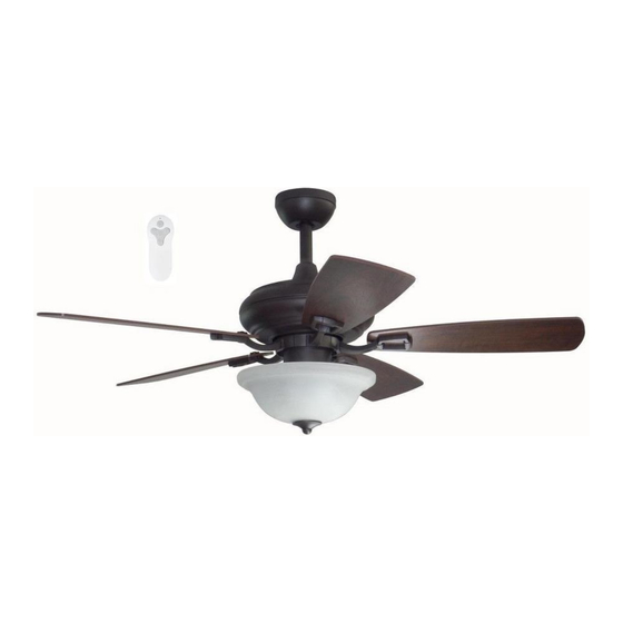
CONNEXXTION
MODEL #TLEII44BNK5L
TLEII44OSB5L
TLEII52BNK5L
TLEII52OSB5L
Español p. 20
016888
016889
016890
®
4009654
Advertisement
Table of Contents

Subscribe to Our Youtube Channel
Related Manuals for Litex Industries CONNEXXTION TLEII44BNK5L


Summary of Contents for Litex Industries CONNEXXTION TLEII44BNK5L
- Page 1 ITEM #016887 016888 016889 016890 ® CONNEXXTION MODEL #TLEII44BNK5L TLEII44OSB5L TLEII52BNK5L TLEII52OSB5L Español p. 20 Express Assembly No Tools Required ATTACH YOUR RECEIPT HERE 4009654 Purchase Date Questions, problems, missing parts? Before returning to your retailer, call our customer service department at 1-800-527-1292, 8:30 a.m.
-
Page 2: Table Of Contents
TABLE OF CONTENTS Safety Information ......................... 2 Package Contents ........................ 4 Hardware Contents ........................... 5 Preparation ........................... 5 Initial Installation ........................5 Installing Safety Cable ......................8 Wiring ..........................9 Final Installation ........................11 Installing Fan Without Light Kit ....................14 Operating Instructions ...................... - Page 3 SAFETY INFORMATION WARNING To reduce the risk of fire, electrical shock or personal injury, mount fan to outlet box marked "ACCEPTABLE FOR FAN SUPPORT OF 35 LBS. OR LESS" and use mounting screws provided with the outlet box. Most outlet boxes commonly used for the support of lighting fixtures are not acceptable for fan support and may need to be replaced.
-
Page 4: Package Contents
PACKAGE CONTENTS PART DESCRIPTION QUANTITY PART DESCRIPTION QUANTITY Downrod (preassembled) Switch Housing Cap Screw (preassembled) Canopy (preassembled) Finial (preassembled) Mounting Bracket Glass Shade Motor Housing Rubber Washer Yoke Cover (preassembled) (preassembled) Light Kit Fitter Balancing Kit (preassembled) Blade Arm Blade Blade Arm Screw Bulb (preassembled) -
Page 5: Hardware Contents
HARDWARE CONTENTS (shown actual size) Three-C Clip Clip Qty. 1 (preassembled) Qty. 15 + 1 extra Qty. 6 PREPARATION Before beginning assembly of product, make sure all parts are present. Place motor on carpet or on foam to avoid damage to finish. Compare parts with package contents list and hardware contents list. If any part is missing or damaged, do not attempt to install, operate or assemble the product. - Page 6 INITIAL INSTALLATION 2. Determine mounting method to use. A. Standard mount B. Angle mount Note: Flushmount and closemount options are not available for this fan. IMPORTANT: If using the angle mount, ensure the ceiling angle is not steeper than 19°. 19°...
- Page 7 INITIAL INSTALLATION You may need to cut the lead wires back to simplify the wiring. If you decide to cut back the lead wires, it is suggested you do so in the following manner: 8 in. Take the lead wires and make sure you have pulled them all the way through the top of the downrod.
-
Page 8: Installing Safety Cable
INSTALLING SAFETY CABLE Adjust safety cable (Z) length by loosening screw and nut on the safety cable vice and pulling on the Loop cable. Adjust slack in cable to a hands length and secure vice by re-tightening screw and nut Wood securely. -
Page 9: Wiring
WIRING WARNING: To reduce the risk of fire, electrical shock or personal injury, each quick connect clip provided with this fan is designed to accept only one 12-gauge house wire and one lead wire from the fan. If your house wire is larger than 12-gauge or there is more than one house wire to connect to the corresponding fixture lead wires, consult an electrician. - Page 10 WIRING Wrap electrical tape (not included) around each individual clip (CC) down to the wire. WARNING: Make sure no bare wire or wire strands are visible after making connections. Place green and white connections on opposite side of box from the black and blue connections. Gently push wires and clips (CC) into outlet box.
-
Page 11: Final Installation
FINAL INSTALLATION Raise canopy (B) toward ceiling and allow it to attach to mounting bracket (C) using the magnets mounted on each side of the mounting bracket (C). Magnet 2. Align the preassembled blade screw posts (J) on blade arms (S) with the holes on a blade (G). Press up on the blade arm firmly so the blade screw posts (J) come through the holes in the blade (G), Friction... - Page 12 FINAL INSTALLATION Insert the end of one blade arm (S) into the keyhole slot on the motor housing (D). Twist blade arm (S) clockwise to lock in place. Repeat with remaining blade arms (S). Keyhole Slot Should it become necessary to remove blade arm (S) from motor housing (D), follow these steps: Remove blade arm screws (T) and washers (U) from underside of motor housing (D) and remove blade arm...
- Page 13 FINAL INSTALLATION Install bulbs (H). CAUTION: When replacing bulb(s), allow bulb(s) and glass shade to cool down before touching. Place rubber washer (Q) inside glass shade (P) over center hole. Align hole in center of glass shade (P) with threaded rod on light kit fitter (F). Push up gently on glass shade (P) until threaded rod comes through hole.
-
Page 14: Installing Fan Without Light Kit
INSTALLING FAN WITHOUT LIGHT KIT If you do NOT wish to use the light kit, remove 3 switch housing cap screws (N) from switch housing cap (M) located on switch housing preassembled to motor housing (D). Pull down gently on switch housing cap (M). -
Page 15: Operating Instructions
OPERATING INSTRUCTIONS CAUTION: The remote control transmitter can be programmed to multiple receivers or fans. If this is not desired, turn wall switch off to any other programmable receiver or fan. FCC Compliance Notice for Remote Control Modifications not approved by the party responsible for compliance could void the user's authority to operate the equipment. - Page 16 OPERATING INSTRUCTIONS 2. Restore electrical power. Within 30 seconds of restoring electrical power, press and hold the “0” button on the remote control transmitter for 5 seconds or until light on the fan blinks twice. Use the remote control transmitter to test the light and fan functions to confirm the learning process is complete.
-
Page 17: Care And Maintenance
OPERATING INSTRUCTIONS 4a. In warmer weather, setting the reverse switch in the DOWN position will result in downward airflow creating a wind chill effect. 4b. In cooler weather, setting the reverse switch in the UP position will result in upward airflow that can help move stagnant, hot air off the ceiling area. -
Page 18: Troubleshooting
TROUBLESHOOTING WARNING: Before beginning work, shut off the power supply to avoid electrical shock. PROBLEM POSSIBLE CAUSE CORRECTIVE ACTION Fan does not move. 1. Reverse switch not engaged. 1. Push switch firmly either up or down. 2. Power is off or fuse is blown. 2. -
Page 19: Limited Lifetime Warranty
Contact Customer Service at 1-800-527-1292 to arrange for return of fan. Return fan, shipping prepaid, to Litex Industries, Ltd. We will repair or ship you a replacement fan, and we will pay the return shipping cost.
Need help?
Do you have a question about the CONNEXXTION TLEII44BNK5L and is the answer not in the manual?
Questions and answers