Table of Contents
Advertisement
Available languages
Available languages
Quick Links
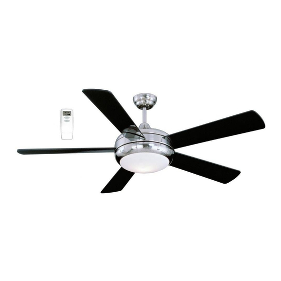
Installation Guide
For Models:
TIT52SCH5LR
TIT52WW5LR
net weight of fan: 21.54 lb (9.77 kg)
READ THESE INSTRUCTIONS AND
AND SAVE THEM FOR FUTURE USE
Table of Contents:
Safety Tips. pg. 1
Unpacking Your Fan. pg. 2
Parts Inventory. pg. 2
Installation Preparation. pg. 3
Hanging Bracket Installation. pg. 3
Fan Assembly. pgs. 4 - 5
Wiring. pg. 6
Canopy Assembly. pg. 6
Final Assembly. pg. 7
Remote Control Operation. pg. 8
Testing Your Fan. pg. 8
Troubleshooting. pg. 9
Warranty. pg. 9
Parts Replacement. pg. 9
PRINTED IN CHINA
Advertisement
Table of Contents

Related Manuals for Litex Industries TIT52SCH5LR


Summary of Contents for Litex Industries TIT52SCH5LR
-
Page 1: Table Of Contents
READ THESE INSTRUCTIONS AND AND SAVE THEM FOR FUTURE USE Installation Guide For Models: TIT52SCH5LR TIT52WW5LR Table of Contents: Safety Tips. pg. 1 Unpacking Your Fan. pg. 2 Parts Inventory. pg. 2 Installation Preparation. pg. 3 Hanging Bracket Installation. pg. 3 Fan Assembly. -
Page 2: Safety Tips
SAFETY TIPS. WARNING: To reduce the risk of electrical shock, turn off the electricity to the fan at the main fuse box or circuit panel before you begin the fan installation or before servicing the fan or installing accessories. READ ALL INSTRUCTIONS AND SAFETY INFORMATION CAREFULLY BEFORE INSTALLING YOUR FAN AND SAVE THESE INSTRUCTIONS. CAUTION: To avoid personal injury, the use of gloves may be necessary while handling fan parts with sharp edges. -
Page 3: Unpacking Your Fan
1. Unpacking Your Fan. Carefully open the packaging. Remove items from Styrofoam inserts. Remove motor housing and place on carpet or Styrofoam to avoid damage to finish. Do not discard fan carton or Styrofoam inserts should this fan need to be returned for repairs. -
Page 4: Installation Preparation
3. Installation Preparation. blade edge To prevent personal injury and damage, ensure inches 7 feet (76cm) that the hanging location allows the blades a (2.13m) clearance of 7 feet (2.13m) from the floor and 30in. (76cm) from any wall or obstruction. 12ft. -
Page 5: Fan Assembly. Pgs
5. Fan Assembly. Remove 6 screws and washers from yoke plate (located on top plate on top of motor housing) and set aside. Lift yoke plate and top plate to remove from motor housing and set aside. yoke plate Time Saver: Washers for blade screws can be set hole for reverse on each blade screw prior to installing blades. - Page 6 5. Fan Assembly. (cont.) Tip: To prepare for threading electrical wires electrical wiring through downrod, apply a small piece of electrical tape to the ends of the electrical wires--this will keep the wires together when downrod threading them through the downrod. canopy Loosen yoke set screws and nut at top of motor housing.
-
Page 7: Wiring
6. Wiring. WARNING: Turn off circuit breakers to current fixture from breaker panel and be sure switch is turned to the OFF position. ground (green CAUTION: Be sure outlet box is properly or bare) white supply wire grounded and that a ground wire (GREEN or Bare) is present. -
Page 8: Final Assembly
nodule 8. Final Assembly. Align slots on shade with nodules on fitter plate (located on underside of motor housing). fitter plate Gently push up on shade and turn to the RIGHT (clockwise) until it slides completely into place. 9. Automated Learning Process./ Activating Code. -
Page 9: Remote Control Operation
10. Remote Control Operation. light dimmer setting button - Tap once to turn LIGHT ON or OFF. Liquid crystal display shows the amount of fan setting brightness as a percentage. Holding the button light button down for more than 2 seconds will cycle light fan button through brightness settings. -
Page 10: Troubleshooting
2. Verify that reverse switch is set completely in either Service at 1-800-527-1292 to arrange for return of fan. direction. Return fan, shipping prepaid, to Litex Industries, Ltd. We will 3. Verify that receiver is wired properly. repair or ship you a replacement fan, and we will pay the 4. - Page 11 LEER ESTAS INSTRUCCIONES Y GUARDARLAS PARA UTILIZACIÓN FUTURA Guía de instalación Para modelos: TIT52SCH5LR TIT52WW5LR Índice de materias: Sugerencias de seguridad. Pág. 1 Desempaquetado del ventilador. Pág. 2 Inventario de piezas. Pág. 2 Preparación para la instalación. Pág. 3 Instalación del soporte de montaje. Pág. 3 Ensamblaje del ventilador.
- Page 12 SUGERENCIAS DE SEGURIDAD. ADVERTENCIA: Para evitar la posibilidad de una descarga eléctrica, desconectar la corriente en la caja de fusibles principal o el interruptor protector antes de iniciar la instalación del ventilador o antes de repararlo o instalar accesorios. LEER TODAS LAS INSTRUCCIONES E INFORMACIÓN DE SEGURIDAD CUIDADOSAMENTE ANTES DE INSTALAR SU VENTILADOR Y GUARDAR ESTAS INSTRUCCIONES.
- Page 13 1. Desempaquetado del ventilador. Abrir el empaque cuidadosamente. Sacar los artículos del embalaje. Sacar el motor y ponerlo en una alfombra o en el embalaje para evitar rayar el acabado. Guardar la caja de cartón o el empaquetamiento original en caso de que tenga que mandar el ventilador para alguna reparación.
- Page 14 3. Preparación para la instalación. borde del aspa Para prevenir daño corporal y otros daños, estar seguro de que el lugar en donde va a colgar el 76cm ventilador le permite un espacio libre de 2,13m 2,13m pulg.) (7 pies) entre las puntas de las aspas y el piso y (7 pies) 76cm (30 pulg) entre las aspas y cualquier pared u otra obstrucción.
- Page 15 5. Ensamblaje del ventilador. Sacar 6 tornillos y arandelas de la placa del cuello (localizada en la placa superior del bastidor del motor) y ponerlos a un lado. Levantar la placa del placa del cuello cuello y la placa superior para quitarlas del bastidor del motor y ponerlas a un lado.
- Page 16 5. Ensamblaje del ventilador. (cont.) Sugerencia: Para preparar los cables para cableado pasarlos por el tubo, poner un pedacito de cinta aisladora en la punta de los cables--esto tubo mantendrá los cables juntos al pasarlos por el tubo. cubierta Aflojar los tornillos de fijación del cuello y la decorativa tuerca de la parte superior del bastidor del cubierta...
- Page 17 6. Instalación eléctrica. ADVERTENCIA: Apagar los cortacircuitos en el panel de electricidad que suplen corriente a la caja de salida y asegurarse de que el interruptor toma de de luz esté APAGADO. alambre conductor blanco tierra (verde o pelada) alambre conductor negro PRECAUCIÓN: Asegurarse de que la caja de salida esté...
- Page 18 8. Instalación final. nódulo Alinear las ranuras en la pantalla con los nódulos en la placa de conexión (localizada en la parte inferior del bastidor del motor). Empujar la pantalla suavemente placa de hacia arriba y girarla hacia la DERECHA (en sentido de conexión las agujas del reloj) hasta que se quede encajada.
- Page 19 10. Funcionamiento del control remoto. posición del reductor de luz Botón - Tocar ligeramente una sola vez para ENCENDER o APAGAR la LUZ. La pantalla de posición del cristal líquido muestra la brillantez de la luz como ventilador un porcentaje. El oprimir el botón por más de botón de la luz 2 segundos hace que pase a todas las posiciones...
- Page 20 Soluciones: garantía. 1. Verificar que se instaló correctamente la bombilla. Ni Litex Industries ni el fabricante se harán responsables 2. Verificar que se hizo correctamente la conexión de cables por lo que pasa por una instalación inadecuada o el uso en la cubierta decorativa.
Need help?
Do you have a question about the TIT52SCH5LR and is the answer not in the manual?
Questions and answers