Table of Contents
Advertisement
Quick Links
OPERATOR'S MANUAL
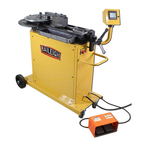
MULTI-PURPOSE ROTARY DRAW BENDER
MODEL: MPB-275
Baileigh Industrial, Inc.
P.O. Box 531
Manitowoc, WI 54221-0531
Phone: 920.684.4990
Fax: 920.684.3944
sales@baileigh.com
REPRODUCTION OF THIS MANUAL IN ANY FORM WITHOUT WRITTEN APPROVAL OF BAILEIGH INDUSTRIAL, INC.
IS PROHIBITED. Baileigh Industrial, Inc. does not assume and hereby disclaims any liability for any damage or loss
caused by an omission or error in this Operator's Manual, resulting from accident, negligence, or other occurrence.
Rev. 10/2018
© 2018 Baileigh Industrial, Inc.
Advertisement
Table of Contents

Subscribe to Our Youtube Channel
Related Manuals for Baileigh Industrial MPB-275


Summary of Contents for Baileigh Industrial MPB-275
- Page 1 REPRODUCTION OF THIS MANUAL IN ANY FORM WITHOUT WRITTEN APPROVAL OF BAILEIGH INDUSTRIAL, INC. IS PROHIBITED. Baileigh Industrial, Inc. does not assume and hereby disclaims any liability for any damage or loss caused by an omission or error in this Operator’s Manual, resulting from accident, negligence, or other occurrence.
-
Page 2: Table Of Contents
Table of Contents THANK YOU & WARRANTY ..................1 INTRODUCTION ......................3 GENERAL NOTES ......................3 SAFETY INSTRUCTIONS ....................4 SAFETY PRECAUTIONS ....................7 Dear Valued Customer: ....................7 TECHNICAL SPECIFICATIONS ..................9 TECHNICAL SUPPORT ....................9 UNPACKING AND CHECKING CONTENTS ..............10 Cleaning ........................ - Page 3 Electrical Components ....................33 TROUBLESHOOTING ....................34 ARC LENGTH TABLE ....................35 PARTS DIAGRAM ......................36 Base Assembly Parts Diagram .................. 36 Gear Box Parts Diagram ................... 37 Top and Bottom Plate Assembly Parts Diagram ............38 Lead Screw Assembly Parts Diagram ............... 39 Actuator Assembly Parts Diagram ................
-
Page 4: Thank You & Warranty
THANK YOU & WARRANTY Thank you for your purchase of a machine from Baileigh Industrial. We hope that you find it productive and useful to you for a long time to come. Inspection & Acceptance. Buyer shall inspect all Goods within ten (10) days after receipt thereof. Buyer’s payment shall constitute final acceptance of the Goods and shall act as a waiver of the Buyer’s rights to inspect or reject the... - Page 5 Baileigh Industrial makes every effort to ensure that our posted specifications, images, pricing and product availability are as correct and timely as possible. We apologize for any discrepancies that may occur. Baileigh Industrial reserves the right to make any and all changes deemed necessary in the course of business including but not limited to pricing, product specifications, quantities, and product availability.
-
Page 6: Introduction
After receiving your equipment remove the protective container. Do a complete visual inspection, and if damage is noted, photograph it for insurance claims and contact your carrier at once, requesting inspection. Also contact Baileigh Industrial and inform them of the unexpected occurrence. Temporarily suspend installation. -
Page 7: Safety Instructions
IMPORTANT PLEASE READ THIS OPERATORS MANUAL CAREFULLY It contains important safety information, instructions, and necessary operating procedures. The continual observance of these procedures will help increase your production and extend the life of the equipment. SAFETY INSTRUCTIONS LEARN TO RECOGNIZE SAFETY INFORMATION This is the safety alert symbol. - Page 8 SAVE THESE INSTRUCTIONS. Refer to them often and use them to instruct others. PROTECT EYES Wear safety glasses or suitable eye protection when working on or around machinery. PROTECT AGAINST NOISE Prolonged exposure to loud noise can cause impairment or loss of hearing.
- Page 9 BEWARE OF PINCH POINTS Keep hands and fingers away from the drive mechanisms, cylinders, ratchets, and other moving linkage while the machine is in operation. HYDRAULIC HOSE FAILURE Exercise CAUTION around hydraulic hoses in case of a hose or fitting failure. HIGH VOLTAGE USE CAUTION IN HIGH VOLTAGE AREAS.
-
Page 10: Safety Precautions
SAFETY PRECAUTIONS Metal working can be dangerous if safe and proper operating procedures are not followed. As with all machinery, there are certain hazards involved with the operation of the product. Using the machine with respect and caution will considerably lessen the possibility of personal injury. However, if normal safety precautions are overlooked or ignored, personal injury to the operator may result. - Page 11 7. Do not force tool. Your machine will do a better and safer job if used as intended. DO NOT use inappropriate attachments in an attempt to exceed the machines rated capacity. 8. Use the right tool for the job. DO NOT attempt to force a small tool or attachment to do the work of a large industrial tool.
-
Page 12: Technical Specifications
TECHNICAL SPECIFICATIONS Solid Square Capacity 1" x 1" (25.4 x 25.4mm) Solid Round Capacity 1" (25.4mm) Flat Bar Stock Capacity 1/2" x 2" (12.7 x 50.8mm) Easy Way Pipe Schedule 40 1-1/4" (31.75mm) Bend Direction Bi-Directional Max. RPM 6 RPM Maximum Bend Speed 5 second 180 degree Degree of Bend (Max) -
Page 13: Unpacking And Checking Contents
UNPACKING AND CHECKING CONTENTS Your Baileigh machine is shipped complete. Separate all parts from the packing material and check each item carefully. Make certain all items are accounted for before discarding any packing material. WARNING: SUFFOCATION HAZARD! Immediately discard any plastic bags and packing materials to eliminate choking and suffocation hazards to children and animals. -
Page 14: Transporting And Lifting
TRANSPORTING AND LIFTING NOTICE: Lifting and carrying operations should be carried out by skilled workers, such as a truck operator, crane operator, etc. If a crane is used to lift the machine, attach the lifting chain carefully, making sure the machine is well balanced. Follow these guidelines when lifting with truck or trolley: •... -
Page 15: Assembly And Set Up
• Remove scrap and waste materials regularly, and make sure the work area is free from obstructing objects. • If long lengths of material are to be fed into the machine, make sure that they will not extend into any aisles. •... -
Page 16: Getting To Know Your Machine
GETTING TO KNOW YOUR MACHINE... -
Page 17: General Design Description
The MPB-275 Bending Machine you have purchased is built of solid steel ensuring maximum rigidity. Tongue and groove design with grade 8 bolts throughout provides very high rigidity and stability. -
Page 18: Electrical
ELECTRICAL CAUTION: HAVE ELECTRICAL UTILITIES CONNECTED TO MACHINE BY A CERTIFIED ELECTRICIAN! Check if the available power supply is the same as listed on the machine nameplate. WARNING: Make sure the grounding wire (green) is properly connected to avoid electric shock. DO NOT switch the position of the green grounding wire if any electrical plug wires are switched during hookup. - Page 19 • Improper connection of the equipment-grounding conductor can result in risk of electric shock. The conductor with insulation having an outer surface that is green with or without yellow stripes is the equipment-grounding conductor. If repair or replacement of the electric cord or plug is necessary, do not connect the equipment-grounding conductor to a live terminal.
-
Page 20: Operation
OPERATION CAUTION: Always wear proper eye protection with side shields, safety footwear, and leather gloves to protect from burrs and sharp edges. CAUTION: Keep hands and fingers clear of the dies and swing arms. Stand to the front of the machine to avoid getting hit with the material during the bending process. -
Page 21: Programmer Display And Key Functions
4. From the RMD MAIN SCREEN you will first select the direction of rotation to used during the bend. The standard direction is Clock Wise. If the non- standard (counter-clock wise) bend direction is chosen, a Warning screen is displayed, this is to ensure the proper tooling is chosen for a given bend direction. -
Page 22: Delete Program
Delete Program 1. Follow the above steps to get to the edit screen and press and hold the CLEAR PROGRAM button to erase all of the bend data for the selected program. Run Program 1. Select this feature if you want to run an existing program. 2. -
Page 23: Custom Manual Bend
Custom Manual Bend 1. From the RMD MAIN SCREEN press the Manual Mode button. 2. Press the Bend box on the screen and when the key pad appears, enter the desired bend angle value and press enter. 3. If desired, press the Springback box to enter a value that the material will spring back after the bend. -
Page 24: Oem Menu & Homing
5. Insert the material, and when clear, use the foot pedals to rotate the bend plate. The bend plate will only stop when the foot pedal is released. 6. Use the Digital Read Out (DRO) on screen or the dial indicator on the bend plate to determine the angle of bend. -
Page 25: Creating A Program
Creating a Program 1. Choose PROGRAM MODE from the RMD MAIN SCREEN. 2. Select a program number from 1 to 140. 3. When you reach the desired program number, press, VIEW EDIT. 4. On the edit screen enter the desired PROGRAM NAME by touching that field. -
Page 26: Running A Program
Running a Program 1. Choose PROGRAM MODE from the RMD MAIN SCREEN. 2. Choose the program you wish to select by entering a number or by using the up down arrow keys. After selecting the program touch the RUN button and the program parameters will be displayed. -
Page 27: Diagram 1
Diagram 1... -
Page 28: Diagram 2
Diagram 2... -
Page 29: Understanding Springback
UNDERSTANDING SPRINGBACK Springback can be difficult to understand. As material is bent, the materials yield strength resists being formed. As a final degree is reached, the machine will have enough power to hold the bend at a set degree, but as the pressure of the machine is released, the material has a resistance built in, so it “springs back”... -
Page 30: Material Insertion
• Another program available is BEND-TECH which is a program specifically designed for tube bending and will give you all of the required data to make a part. This software is available from Baileigh Industrial. • Bending with a rotary draw bender requires determining the start of bend point which will line up with the “0”... -
Page 31: Material Removal / Advancement
Important: Liberally apply lubricant along the 1/2 of the material on the side toward and contacts with the counterdie with a WD-40 style lubricant or equivalent. Do not lubricate the bending pins beyond rust prevention. Lubricating the bending pins will encourage slipping of material in the bending pins. -
Page 32: Bending Glossary
BENDING GLOSSARY Arc Length The length of material along the centerline of the tubing Distance in inches from the center of curvature to the centerline Centerline Radius (CLR) axis of the tube bending or pipe bending bends. Abbreviated as CLR. See Tube Bending and Pipe Bending Diagram Angle in degrees to which the tube/pipe bends are formed (i.e. -
Page 33: Bending Suggestions
• If using BAILEIGH INDUSTRIAL’s standard counterdie is not producing desired results, roller counter dies are also available. • BAILEIGH INDUSTRIAL has both steel rollers as well as plastic rollers. Plastic rollers are used primarily for polished aluminum. Steel rollers would be used for non-polished materials. -
Page 34: Lubrication And Maintenance
LUBRICATION AND MAINTENANCE WARNING: Make sure the electrical disconnect is OFF before working on the machine. Maintenance should be performed on a regular basis by qualified personnel. Always follow proper safety precautions when working on or around any machinery. • Check daily for any unsafe conditions and fix immediately. •... -
Page 35: Electrical Schematic
ELECTRICAL SCHEMATIC Horner ( XLE or XLT) Hexle 102 or HE-XT102 Programmer Orange J1 Connector Black J2 Connector... -
Page 36: Electrical Components
Electrical Components WARNING: Make sure the electrical disconnect is OFF before working on the machine. Use the lockout provided on the main disconnect switch. Wait at least 1 min before working on any circuit, because the VFD capacitors may have energy stored. Maintenance should be performed on a regular basis by qualified personnel. -
Page 37: Troubleshooting
TROUBLESHOOTING FAULT PROBABLE CAUSE REMEDY Check input power and verify Wrong or non-existent input Machine does not power voltage power source. Blown fuse or Check and replace fuses. Reset tripped circuit breaker. circuit breakers Let oil purge from gearbox and Oil leaking from breather Normal expansion of gearbox oil take no further action. -
Page 38: Arc Length Table
ARC LENGTH TABLE EXAMPLE: Arc Length = Constant x Bend Radius. Example: 90deg bend with 6” clr EXAMPLE: 1.575 (from table) x 6” (clr) = 9.45” (Arc Length) For bends more than 90deg, Constants can be added together. Degrees Constant Degrees Constant Degrees... -
Page 39: Parts Diagram
PARTS DIAGRAM Base Assembly Parts Diagram... -
Page 40: Gear Box Parts Diagram
Gear Box Parts Diagram... -
Page 41: Top And Bottom Plate Assembly Parts Diagram
Top and Bottom Plate Assembly Parts Diagram... -
Page 42: Lead Screw Assembly Parts Diagram
Lead Screw Assembly Parts Diagram... -
Page 43: Actuator Assembly Parts Diagram
Actuator Assembly Parts Diagram... -
Page 44: Spiral Bend Plate Counter Die Assembly Parts Diagram
Spiral Bend Plate Counter Die Assembly Parts Diagram... -
Page 45: Pivot Pin Assembly Parts Diagram
Pivot Pin Assembly Parts Diagram... -
Page 46: Roller Counter Die Assembly Parts Diagram
Roller Counter Die Assembly Parts Diagram... -
Page 47: Spiral Bend Plate Assembly Parts Diagram
Spiral Bend Plate Assembly Parts Diagram... -
Page 48: Control Box Assembly Parts Diagram
Control Box Assembly Parts Diagram... -
Page 49: Tool Box Assembly Parts Diagram
Tool Box Assembly Parts Diagram... -
Page 50: Parts List
Parts List Item Part Number Description Qty. M275-5A020 M275 Cart PP-0043 1.0 ID X 1.1875 OD X 0.75 LG Bushing PP-0035 1" Set Screw Collar PP-0064 8" Rubber Wheel PP-0048 4.0 Inch Caster STD. 3/8-16 X 1 Carriage Bolt 3/8 Lock Washer Std. - Page 51 Item Part Number Description Qty. STD. Ext. Retaining Ring M275-6A001 Bottom Plate M8 X 1.25 X 25 SHCS M8 X 1.25 X 25 Hex Flange 1/2 LOCK WASHER Std. 1/2-13 X 2.50 HHCS M12 X 1.75 X 35 SHCS PP-0023 Cord Grip M275-6A003 Side Frame...
- Page 52 Item Part Number Description Qty. PP-0935 1.0 ID X 1.5 OD X .0625 THK 1" Ext. Retaining Ring M275-7A022 Guide Shaft M10 X 1.5 X 45 SHCS PP-0137-V2 Fiama Counter PP-0036 1.0 Clamp Collar (Split) M275-7A023 Lead Screw Stop Nut M250-5A008 Electrical Box for XLT M275-6A036...
- Page 53 Item Part Number Description Qty. M275-6A024 Arc Plate M8 X 1.25 X 16 SHCS M275-6A034 Pointer M6 FLAT WASHER Std. ME-M250-7A010 Lead Screw Nut Insert M275-6A028 Arc Slide M275-6A027 Stop Bar M275-6A029 Stop Block M275-7A011 Stop Shaft M275-6A035 Stop Plate M6 X 1.0 X 16 FHCS M275-7A025...
- Page 54 NOTES...
- Page 55 NOTES...
- Page 56 BAILEIGH INDUSTRIAL, INC. 1625 D , WI 54220 UFEK RIVE ANITOWOC : 920. 684. 4990 F : 920. 684. 3944 HONE www.baileigh.com BAILEIGH INDUSTRIAL LTD. U WIFT OINT WIFT ALLEY NDUSTRIAL STATE UGBY , CV21 1QH U IDLANDS NITED INGDOM...
Need help?
Do you have a question about the MPB-275 and is the answer not in the manual?
Questions and answers